Note: Descriptions are shown in the official language in which they were submitted.
CA 02762944 2011-11-21
[DESCRIPTION]
[Invention Title]
BICYCLE DERIVING DRIVING FORCE BY MOTOR-GENERATOR
[Technical Field]
The present invention relates to a bicycle which is a means of
short-distance movement favored by men and women of all ages, and
more specifically to a bicycle in which a motor-generator is mounted on
the rear wheel of the bicycle, and the electric power obtained from the
motor-generator is stored in a separate battery, and the electric power
stored in the battery is converted into and used for power to rotate the
motor mounted on the rear wheel via the action of a change-over switch,
so that charging is made by carrying out a power generation action in the
case of being propelled by user's power or going downhill, and rotary
force is conveyed to the rear wheel when charging is made to obtain an
electrical driving force to make it possible to use the bicycle
conveniently.
A bicycle is a collective name of relatively light-weight two-
wheeled vehicles in which a front wheel and a rear wheel are connected
by pipes and the rear wheel is connected to a pedal via a chain sprocket,
a derailleur and a chain. When the rider pushes on the pedal, power is
conveyed to the rear wheel to generate the driving force of bicycle.
In such a bicycle, the front wheel is connected via a front fork that
is connected downward to the lower end of a head pipe, and the rear
wheel is connected via a fixed pipe and rear fork that together support a
seat. The head pipe and fixed pipe are connected via the combination of
1
CA 02762944 2011-11-21
a main pipe, support pipe and down pipe.
A handle is placed laterally at the upper end of the head pipe, and
handlebars are fixed at the opposite ends of the handle. The chain
sprocket and pedal are rotatably joined to the lower end of the down pipe
and support pipe, and the derailleur and chain stay are joined to the
rotating axis of the rear wheel that is connected to the lower end of the
rear fork.
However, such an ordinary bicycle obtains a driving force by relying
on a genuine power of user's feet, so riding a bicycle for a long time or
moving a long distance causes a feeling of extreme fatigue. Especially
for a beginner, there is a problem that long-time or long-distance riding
is impossible.
And in order to overcome the limitations that a bicycle has for an
uphill path, a multi-stage derailleur is adopted to make it relatively easy
to climb a hill or an uphill road. But such a derailleur increases the
number of revolutions from the force of pedal conveyed by a chain
sprocket, and obtains a force proportional to it to make it possible to
climb a hill. Because of this, physical strength is consumed proportionally,
and still more kinetic force is required.
Therefore, a recent trend is the marketing of electric bicycles in
which driving force is automatically generated by mounting a separate
electromotive means on the bicycle and providing the rear wheel with a
rotary force from the electromotive means.
Such an electric bicycle comprises a battery for storing electricity
by using household electricity and an electromotive means that is rotated
2
CA 02762944 2011-11-21
and driven by applying the battery electricity. Since the rotary force
generated from the electromotive means is conveyed to the rear wheel
via a power transmission device, it is designed in such a way that running
a bicycle is possible without relying on the user's force.
However, such an electric bicycle cannot be used unless charging
work is carried out after finishing riding the bicycle. Therefore, it has a
problem that excessive power is consumed for charging and the
requirement of a long time for charging results in many limitations in use.
Also, in the case of using an electric bicycle for a long distance or a
long time, the battery discharges completely to cause the loss of the
function as an electric bicycle, then the bicycle should be run by relying
on a user's power as in a conventional ordinary bicycle. Therefore, the
user will feel more serious fatigue and more momentum and physical
power are required as the weight of the electromotive means is added to
the weight of the bicycle, so it is not so efficient.
[Disclosure]
[Technical Problem]
To solve the above-mentioned problems, the present invention is an
application of a bicycle having a motor-generator disclosed in Korean
Patent Application No. 2009-035298 that the applicant of the present
invention filed. Namely, a motor-generator is mounted on a side of the
rear wheel of the bicycle, and a control box and a battery are mounted
under the main pipe of the bicycle, and a change-over switch and a
change speed switch are mounted on the handle of the bicycle.
Accordingly, it is an object of the present invention to provide a
3
CA 02762944 2011-11-21
bicycle in which charging is made via a motor-generator when pedaling
on a downhill or level ground, and electric power of the battery is
conveyed to the rear wheel via the motor-generator to rotate it, so that
the bicycle can have driving force from the motor-generator that can
rationally solve all the problems that the conventional bicycle and
electric bicycle had.
[Technical Solution]
In order to accomplish the foregoing objects, the present invention
provides a bicycle deriving driving force by a motor-generator having a
rotating plate of a nonmagnetic material having a plurality of radially
fixed magnets, fixed plates of a nonmagnetic material which are placed
on both sides of the rotating plate and have a plurality of horizontally
wound coil units corresponding to the magnets, and a rotating axis which
is mounted on the center of the rotating plate and at both ends of which
are fixed the plates through the bearings, the bicycle comprising: a
motor-generator which is mounted on the side of the rear wheel of the
bicycle; a power transmission means including a driving pulley which is
fixed on the shaft where the rear wheel of the bicycle is rotatably
mounted, a driven pulley which is mounted on one end of the rotating
axis mounted on the center of the rotating plate, and a belt which
operatively connects the driving pulley and the driven pulley; a control
box and a battery which are mounted on the bicycle and are connected
with the coil units; and a change-over switch which is mounted on the
handle of the bicycle and converts the motor-generator in such a way
that it can be used selectively as a generator or a motor.
4
CA 02762944 2011-11-21
[Advantageous Effects]
The present invention makes it possible to charge quickly and
effectively via a motor-generator that is operated by the bicycle driving
force on a downhill or level ground, and with charging made, the rotary
force of the motor-generator is conveyed to the rear wheel to generate
electric power, so that electromotive force is produced and stored by
itself, and the driving force of the bicycle can be obtained by using the
stored electric power. Therefore, it is possible to use the bicycle easily
and conveniently for a long time, and it has an effect of much reduced leg
fatigue even in the case of moving a long distance.
[Description of Drawings]
The above objects, features and advantages of the present invention
will become more apparent to those skilled in the related art in
conjunction with the accompanying drawings. In the drawings:
Fig. 1 is an exploded perspective view showing major parts of a
conventional motor-generator;
Fig. 2 is a side view showing the overall construction of a bicycle
according to the present invention;
Fig. 3 is an enlarged rear view showing the rear wheel of the
bicycle according to the present invention;
Fig. 4 is a circuit diagram showing an electromotive means of the
bicycle according to the present invention;
Fig. 5 is a circuit diagram showing the state in which driving force is
provided by the electromotive means in the bicycle according to the
present invention;
CA 02762944 2011-11-21
Fig. 6 is a circuit diagram showing the state in which electric power
is generated by driving force in the bicycle according to the present
invention; and
Fig. 7 is an enlarged rear view showing the rear wheel of the
bicycle according to an embodiment of the present invention.
* Description of Reference Numerals in Drawings
10: Rotating plate 11, 11': Magnet
12: Rotating axis 13: Driven pulley
20, 20': Fixed plate 21, 21': Coil unit
30: Motor-generator
50: Bicycle 51: Rear wheel
52: Shaft 53: Driving pully
54: Belt 55: Handle
56: Change-over switch 57: Speed change switch
60: Control box 61: Transformer
62: Rectifier diode 63: Polarity change-over unit
64: Phase sensor 65: Phase delivery unit
66: Variable speed unit 70: Battery
80: Support
[Best Mode]
Hereinafter, preferred embodiments of the present invention will be
described in more detail through the following examples.
Prior to this, terms or words used in the specification and claims
should not be construed as limited to a lexical meaning, and should be
understood as appropriate notions by the inventor based on that he/she
6
CA 02762944 2011-11-21
is able to define terms to describe his/her invention in the best way to be
seen by others.
Fig. 1 is an exploded perspective view showing major parts of a
conventional motor-generator.
The motor-generator disclosed in Korean Patent Application No.
2009-035298 that the applicant of the present invention filed includes a
rotating plate 10 on which a plurality of magnets 11 and 11' are radially
attached and fixed plates 20 and 20' on which a plurality of coil units 21
and 21' are radially placed and horizontally wound. The fixed plates 20
and 20' are placed in separation at a predetermined interval on both
sides of the rotating plate 10. A rotating axis 12 is fitted on the center of
the rotating plate 10, and the fixed plates 20 and 20' are rotatably
mounted on both ends of the rotating axis 12 by bearings.
Accordingly, when the rotating plate 10 is rotated by the power of
pedaling, the electric charge having a predetermined polarity generated
from the magnets 11 and 11' is applied to the coil units 21 and 21', and
the electricity generated from the coil units 21 and 21' by the electric
charge is stored in the battery by way of a transformer and rectifier
diode. Therefore, this system can be used as a chargeable generator.
Conversely, when external electricity is applied to the coil units 21
and 21', the electric charge generated from the coil units 21 and 21'
interfere with the polarity of the magnets 11 and 11' of the rotating plate
to generate attractive force and repulsive force between them.
Therefore, it is possible to use the rotating plate 10 as a continuously
rotating motor via alternating transfer supply of external electricity.
7
CA 02762944 2011-11-21
Fig. 2 is a side view showing the overall construction of a bicycle
according to the present invention, and Fig. 3 is an enlarged rear view
showing the rear wheel of the bicycle according to the present invention,
and Fig. 4 is a circuit diagram showing the electromotive means of the
bicycle according to the present invention.
As described above, a motor-generator 30 having the rotating plate
and fixed plates 20 and 20' are mounted on the side of the rear wheel
51 of the bicycle 50. A separate driving pulley 53 is fixed together on the
shaft 52 where the rear wheel 51 of the bicycle 50 is rotatably installed.
A separate driven pulley 13 is fixed on one end of the rotating axis 12
that is mounted on the center of the rotating plate 10. In this state, by
operatively connecting the driving pulley 53 and driven pulley 13 via the
belt 54, power transmission between the rotating body and rear wheel is
made by these power transmission means.
In particular, by adjusting the rotation ratio of the driven pulley 13
and driving pulley 53, electricity generation or electromotive efficiency
can be improved. Namely, by forming the diameter of the driven pulley
13 to be small and the diameter of the driving pulley 53 to be large, the
driven pulley 13 rotates more while the driving pulley 53 makes one
rotation. Therefore, a larger quantity of electricity storage is possible
during generation, and an increase of rotary force is possible during
electromotive operation.
And it is preferable to use a timing belt for the belt 54 for more
accurate transmission of rotary force. Also for the driven pulley 13 and
driving pulley 53 that are operatively connected via the timing belt, it is
8
CA 02762944 2011-11-21
preferable that they have sawteeth in a form corresponding to the timing
belt. Any kind of construction that can transmit power, such as the timing
belt 54, driven pulley 13 and driving pulley 53, can be used. For example,
besides the structure of timing belt as described above, a power
transmission structure with a chain and sprocket can also be used.
In the process of mounting a motor-generator 30 on one side of the
rear wheel 51 of the bicycle 50, the lower end of one fixed plate 20 is
fastened directly to the shaft 52 of the rear wheel 51, and the upper end
of the fixed plate 20 is installed by using a separate support 80 that is
fixed to the bicycle 50. Accordingly, the motor-generator 30 can
maintain a stable fixed state for the bicycle 50, and a control box 60 and
battery 70 connected to the motor-generator 30 can be mounted in the
necessary portion of the bicycle 50.
In addition, on the handle 55 of the bicycle 50 are mounted a
change-over switch 56 for selective use of a motor or generator and a
speed change switch 57 that can adjust the rotation velocity of the motor
40 in case the motor-generator 30 is used as a motor.
In the bicycle of the present invention having such a construction,
storage of electricity is made by a transformer 61 and a rectifier diode
62 in the control box 60, and the motor is driven by a polarity change-
over unit 63 and variable speed unit 66 with a phase sensor 64 and phase
delivery unit 65.
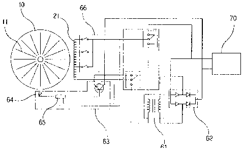
Namely, as shown in Fig. 5, with the battery 70 sufficiently charged,
the change-over switch 56 mounted on the handle of the bicycle 50 is
operated to have the electricity of the battery 70 applied to the coil units
9
CA 02762944 2011-11-21
21 and 21' of the fixed plates 20 and 20', then the rotating plate 10 is
forced to rotate by attractive force and repulsive force acting in polarity
between the electric charges acting on coil units 21 and 21' and magnets
11 and 11'.
At this time, the electricity of the battery 70 is supplied by
repeatedly changing the polarity by the polarity change-over unit 63, so
that the rotating plate 10 can have rotary force of the same direction
continuously. Also, the polarity change-over unit 63 is connected to the
phase sensor 64 that detects the phase of magnets 11 and 11' and the
phase delivery unit 65 that delivers the detected signal of the phase
sensor 64. Therefore, as the magnets 11 and 11' of the rotating plate 10
start rotating, the polarity of the electricity provided from the battery 70
is continuously changed to be supplied to the coil units 21 and 21'. As a
result, the rotating plate 10 is continuously rotated by the attractive
force and repulsive force action on the magnets 11 and 11'.
Especially, to the coil units 21 and 21' placed radially on the fixed
plates 20 and 20' electricity is supplied selectively by a separate variable
speed unit 66. At this time, the rotation velocity and the rotary torque for
the rotating plate 10 can be adjusted by supplying the electricity applied
to the coil units 21 and 21' via the variable speed unit 66 in an individual
or group mode.
Such a variable speed unit 66 can be controlled via the speed
change switch 57 mounted on the handle 55 of the bicycle 50. Namely,
the rotary velocity and rotary force of the rotating plate 10 can be
increased or decreased by changing the supply mode of the electricity
CA 02762944 2011-11-21
applied to each of the coil units 21 and 21' whenever the speed change
switch 57 is operated.
Such a rotation structure of the rotating plate 10 by the battery 70
is described in detail in the above-mentioned preceding patent
application.
Therefore, as the rotating plate 10 is rotated by using the battery
70 as described above, the driven pulley 13 and the driving pulley 53
rotate via the timing belt, and the rotary force of the driving pulley 53 is
directly transmitted to the rear wheel 52, so that it can be rotated by
rotary force.
So in the case of an uphill or level ground, it is possible to use a
bicycle conveniently by operating the motor-generator 30 in such a way
that it plays a role of a motor.
Fig. 6 is a circuit diagram showing the state in which generation is
made by the driving force in the bicycle according to the present
invention. In the case of riding downhill or level ground, the user can
charge the battery 70 as necessary.
Namely, riding is possible without pedaling and only with the weight
of the user and the weight of the bicycle itself when going downhill. In
such a case, the change-over switch 56 mounted on the handle 55 is
operated to have the motor-generator 30 play a role of a generator.
Here, the change-over switch 56 can be operated by the user
pressing it personally, or it can be configured in such a way that the
change-over switch 56 is automatically operated when going downhill for
automatic change-over from the function of motor to the function of
11
CA 02762944 2011-11-21
generator, by mounting on the bicycle a change-over switch 56 of a type
operating according to the angle with respect to the horizon.
As the function is changed to that of a generator, the rotary force of
the rear wheel 51 is transmitted to the rotating plate 10 to rotate it by
force, and then the magnets 11 and 11' of the rotating plate 10 affect the
coil units 21 and 21' of the fixed plates 20 and 20' to generate an electric
charge. As described above, the electric charge generated from the coil
units 21 and 21' is rectified by way of the transformer 61, and alternating
current is converted to direct current by the rectifier diode 62 to have
the battery 70 charged automatically.
In particular, since the above-described motor-generator 30 rotates
in a free running mode in which interference resistance between the
magnets 11 and 11' of the rotating plate 10 and the coil units 21 and 21'
of the fixed plates 20 and 20' does not occur at all, the running power of
the bicycle is not affected even while the above-described generation
action is being carried out.
Thus, the bicycle of the present invention makes selective operation
as a motor or a generator possible on terrain such as downhill or uphill,
so long-time or long-distance riding through continuous charging are
possible as well as convenient use of the bicycle.
Also, as shown in Fig. 7, the motor-generators 30 of the present
invention can be mounted on both sides of the rear wheel 51 as well by
using supports 80. In this case, much higher electromotive force or
generation efficiency can be obtained by the motor-generators 30 on
both sides, so the role as an electromotive bicycle can be achieved more
12
CA 02762944 2011-11-21
sufficiently.
Although the present invention has been described in connection
with the exemplary embodiments illustrated in the drawings, it is only
illustrative. It will be understood by those skilled in the art that various
modifications and equivalents can be made to the present invention.
Therefore, the true technical scope of the present invention should be
defined by the appended claims.
13