Note: Descriptions are shown in the official language in which they were submitted.
= CA 02763023 2011-12-21
TOOL FOR QUALITATIVELY MEASURING A FEATURE OF A SKATE BLADE
[0001] This application is a divisional application of
Canadian serial number
2,619,254 filed February 1,2008.
FIELD OF THE INVENTION -
[0002] The present invention relates to a tool for
qualitatively
measuring a feature of a skate blade, and more particularly to a tool for
qualitatively measuring whether a skate blade has been sharpened to the
correct radius of hollow and/or the profile of the sharpened surface has been
properly centered with respect to the blade.
BACKGROUND OF THE INVENTION
[0003] Figure skaters, hockey players, and speed skaters
utilize
skates with a blade that must be sharpened from time to time. Typically,
= the skate blades are sharpened utilizing a machine that has a rotating
stone and an arcuate shaped outer surface for sharpening a skate blade.
The radius of the arcuate shaped outer surface of the stone may be varied
to produce different depths of hollow in the skate blade or different stones
with different radii of the arcuate shaped outer surface may be used.
Rarely are skate blades sharpened so. that the sharpened surface is
substantially flat and perpendicular with the side faces of the skate blade.
1 .
CA 02763023 2011-12-21
Instead, the skate blade surface is sharpened in a concaved shape so
that a portion of the blade is hollowed out. This produces two sharp
edges. Typically, skaters who desire the ability to turn sharply have their
skates sharpened to produce a larger depth of hollow. Skaters that wish to
skate fast or to spin more freely have their skates sharpened so
that the sharpened surface profile has a relatively smaller depth of hollow.
[0004] Devices have heretofore been known to make
quantitative measurements of the depth of hollow of a sharpened skate
blade. A known depth of hollow indicator tool available from Edge
Specialties, Inc. makes such a quantitative measurement of the depth of
hollow. This depth of hollow tool includes a probe which makes a precise
linear quantitative measurement of the depth of hollow of a sharpened
skate surface. This tool is relatively bulky and relatively expensive,
selling for approximately $225.00. Another tool for quantitatively measuring
the depth of hollow is available from Maximum Edge of Windsor, Ontario
and sells for approximately $150.00. This other tool is also relatively
bulky and is not easily carried by the owner.
[0005] The present invention provides alternatives to the prior art.
SUMMARY OF THE INVENTION
[0006] A tool for qualitatively measuring a feature of a skate
blade. One embodiment of the invention includes a means for qualitatively
determining whether a skate blade has been sharpened properly. In one
2
CA 02763023 2013-10-22
embodiment of the invention, the means for qualitatively determining
whether a skate blade has been sharpened properly includes a means
for determining whether a skate blade has been sharpened squarely, that
is, whether the profile of the sharpened surface has been properly centered
with respect to the side faces of blade. In one embodiment of the
invention, the means for qualitatively determining whether a skate blade
has been sharpened properly includes a radius of hollow indicator means.
In another embodiment of the invention, the means for qualitatively
determining whether a skate blade has been sharpened properly includes
both a means for determining whether a skate blade has been
sharpened squarely, and at least one radius of hollow indicator means.
[0006a] An aspect of the invention includes a tool comprised of a means
for qualitatively determining whether a skate blade has been sharpened
properly and comprises a first leg, the first leg comprising at least one of a
first
substantially flat reference face, an arcuate shaped side edge, and a first
magnet.
[0006b] Another aspect of the invention is a tool comprising a means for
qualitatively determining whether a skate blade, having opposite side faces
and
a sharpened edge, has been sharpened properly that includes a first leg that
engages the sharpened edge and a second leg that engages one of the side
faces of the blade, wherein the first leg comprises a first substantially flat
reference face, and wherein the second leg comprises a second substantially
flat reference face, and wherein the first substantially flat reference face
and
3
CA 02763023 2013-10-22
,
the second substantially flat reference face extend substantially the same
distance and are perpendicular to each other, and wherein the first
substantially flat reference face is adapted to be placed flush on the
sharpened
edge while the second substantially flat reference face is flush against one
of
the side faces of the blade only if the skate blade has been sharpened
squarely, and wherein a gap appears between either the first leg of the tool
and
the sharpened edge or between the second leg of the tool and the side face of
the blade if the sharpened edge has not been sharpened squarely.
[0006c]
Yet another aspect of the present invention is a tool for
qualitatively measuring a feature of a skate blade comprising a first piece
having a first leg having a first substantially flat reference face, and a
second
leg having a second substantially flat reference face. At least one of the
first
leg and the second leg comprise a first magnet. The first substantially flat
reference face and the second substantially flat reference face form a right
angle. There is a second piece having a third leg having a third substantially
flat reference face, and a fourth leg having a fourth substantially flat
reference
face. At least one of the third leg and the fourth leg comprise a second
magnet. The third substantially flat reference face and the fourth
substantially
flat reference face form a right angle. The first piece and the second piece
are
constructed and arranged to balance on the skate blade. The first leg further
comprises a fifth substantially flat reference face. The second leg further
comprises a sixth substantially flat reference face. The third leg further
comprises a seventh substantially flat reference face. The fourth leg further
3a
CA 02763023 2013-10-22
comprises an eighth substantially flat reference face. The sixth substantially
flat reference face comprises one or more level indicators. The eighth
substantially flat reference face comprises one or more level indicators.
[0006d] A further aspect of the present invention is a tool for
quantitatively measuring a feature of a skate blade comprising a first piece
and
a second piece being separate from each other. Each of the first piece and
second piece comprising a first substantially flat leg and second
substantially
flat leg formed at a right angle. The first leg, outer face and the second leg
have a second outer face. The first outer face and the second outer face, face
away from each other. The first outer face includes a plurality of level
indicators.
[0006e] Yet a further aspect of the present invention is a tool for
qualitatively measuring a feature of a skate blade having first and second
side
faces and a ground edge feature. The tool comprises a first piece having a
first
leg and a second leg wherein the first and second legs form a right angle.
Also
included is a first magnet mounted on the first piece, a second piece that is
separate from the first piece has substantially the same size and shape as the
first piece and has a third leg and a fourth leg wherein the third and fourth
legs
form a right angle. A second magnet is mounted in the second piece. One or
more level indicators on the fist piece extend across the width of the surface
on
which they appear. One or more level indicators on the second piece extend
across the width of the surface on which they appear. The level indicators on
3b
CA 02763023 2013-10-22
, .
the first and second pieces have substantially the same appearance. The first
magnet mounts the first piece on one of the side faces of the blade whereby
the first piece extends parallel to the side face of the blade on which it is
mounted and for a distance above the ground edge feature of the blade. The
second magnet mounts the second piece on the ground edge feature of the
blade whereby the second piece extends perpendicular to the first piece and
perpendicular to the side face of the blade on which the first piece is
mounted.
The first and second pieces cross one another at substantially a right angle.
The crossing of the first and second pieces provides an indication on the one
or
more level indicators on at least one of the first or second pieces of the
centering of the ground edge feature of .the blade.
[0007]
Other embodiments of the present invention will become
apparent from the detailed description provided hereinafter. It should
be understood that the detailed description and specific examples, while
indicating the preferred embodiment of the invention, are intended for
purposes of illustration only and are not intended to limit the scope of the
invention.
BRIEF DESCRIPTION OF THE DRAWINGS
[0008]
The present invention will become more fully understood from
the detailed description and the accompanying drawings, wherein:
[0009]
FIG. 1 illustrates a skate having a blade and a tool for
qualitatively measuring a feature of the skate blade.
3c
CA 02763023 2011-12-21
[0010] FIG. 2 is a perspective view of one embodiment of the
invention including a tool for measuring a feature of a skate blade.
[0011] FIG. 3 is a side view of the tool shown in FIG. 2.
[0012] FIG. 4 is an end view of the tool shown in FIG. 2.
[0013] FIG. 5 is an enlarged view of a skate blade with portions
removed and a tool qualitatively for measuring a feature of a skate blade
according to one embodiment of the invention.
[0014] FIG. 6 is an enlarged view of a skate blade and a tool for
qualitatively measuring a feature of a skate blade, according to one
embodiment of the invention, showing a gap between a reference face of the
tool and an edge of the blade when the hollow ground sharpening of the
blade is not centered properly.
[0015] FIG. 7 is an enlarged view of a skate blade and a tool for
qualitatively measuring a feature of the skate blade, according to one
embodiment of the invention, showing a gap between a second reference
face and the side face of a blade when the hollow ground sharpening of the
blade is not properly centered.
[0016] FIG. 8 illustrates, according to one embodiment of the
invention, a tool for qualitatively measuring a feature of the blade, wherein
the tool includes a radius of hollow indicator means.
[0017] FIG. 9 illustrates the use of a tool for qualitatively measuring a
feature of a skate blade, according to one embodiment of the invention,
wherein a radius of hollow indicator means does not match the profile of the
4
CA 02763023 2011-12-21
sharpened surface of a skate and gaps exist between the radius of hollow
indicator means and the sharpened surface.
[0018] FIG. 10
illustrates a tool for qualitatively measuring a feature of
a skate blade, according to one embodiment of the invention, and wherein a
radius of hollow indicator means does not match the profile of the
sharpened surface of a skate.
[0019] FIG. 11
illustrates a tool for qualitatively measuring a feature of a
skate blade, according to one embodiment of the invention.
[0020] FIG. 12
is sectional view of the tool taken along line 12-12 of FIG.
11.
[0021] FIG. 13
illustrates another embodiment of a tool for qualitatively
measuring a feature of a skate blade.
[0022] FIG. 14
illustrates another embodiment of the invention
including a tool for qualitatively measuring a feature of the skate blade
including a pivotally mounted second leg received in a pocket of a first leg
of
the tool.
[0023] FIG. 15
illustrates a tool as shown in FIG. 14 but with the
second leg extended out of the pocket of a first leg of the tool, and wherein
the
second leg includes a magnet in a first position.
[0024] FIG. 16
illustrates a tool as shown in FIG. 15 but with the
'magnet rotated to a second position.
[0025] FIG. 17
is a perspective view of another embodiment of the
invention including a tool for qualitatively measuring a feature of a skate
CA 02763023 2011-12-21
blade having a plurality of radius of hollow indicator means extending
outwardly
from a side edge of a first leg of the tool.
[0026] FIG. 18 is a top view of the tool shown in FIG. 17.
[0027] FIG. 19 is a perspective view of another embodiment of the
invention including a tool for qualitatively measuring a feature of a skate
blade having a plurality of radius of hollow indicator means extending out
of the plane of a first reference face of a first leg of the tool.
[0028] FIG. 20 is a side view of a tool according to one embodiment of
the invention.
[0029] FIG. 21 illustrates a skate having a blade and a tool including a
first piece and a second piece for qualitatively measuring a feature of the
skate
blade, according to one embodiment of the invention.
[0030] FIG. 22A is a perspective view of another embodiment of the
invention including a tool including a first piece and a second piece.
[0031] FIG. 22B is a perspective view of another embodiment of the
invention including a tool including a first piece and a second piece.
[0032] FIG. 23A is a perspective view of another embodiment of the
invention including a second piece of a tool for qualitatively measuring
features
of the skate blade having a magnet in a first position.
[0033] FIG. 23B is a perspective view of another embodiment of the
invention including a second piece of a tool for qualitatively measuring
features
of the skate blade having a magnet in a second position.
[0034] FIG. 23C is a perspective view of another embodiment of the
6
CA 02763023 2011-12-21
invention including a second piece of a tool for qualitatively measuring
features
of the skate blade having a magnet in a third position.
DETAILED DESCRIPTION OF THE PREFERRED EMBODIMENTS
[0035] The following description of the preferred embodiment(s) is
merely exemplary in nature and is in no way intended to limit the invention,
its application, or uses.
[0036] The present invention relates to a tool for qualitatively
measuring a feature of a skate blade, and more particularly to a tool for
qualitatively measuring whether a skate blade has been sharpened to the
correct radius of hollow and for the profile of the sharpened surface has
been properly centered with respect to the blade. One embodiment of the
invention includes a means for qualitatively determining whether a skate
blade has been sharpened properly. In one embodiment of the invention,
the means for qualitatively determining whether a skate blade has been
sharpened properly includes a means for determining whether a skate
blade has been sharpened squarely, that is, whether the profile of the
sharpened surface has been properly centered with respect to the side
faces of blade. In one embodiment of the invention, the means for
qualitatively determining whether a skate blade has been sharpened
properly includes a radius of hollow indicator means. In another
embodiment of the invention, the means for qualitatively determining
whether a skate blade has been sharpened properly includes both a means
7
CA 02763023 2011-12-21
for determining whether a skate blade has been sharpened squarely, and at
least one radius of hollow indicator means.
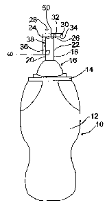
[00371 FIG. 1 illustrates a skate 10 including a boot 12 and a sole
14
attached thereto. A blade holder 16 is attached to the sole 14 by rivets (not
shown) and a blade 18 is attached to the blade holder 16. Blade 18, typically
includes a metal such as stainless steel, and has a first side face 20 and an
opposite second side face 22. Blade 18 includes a surface 50 for
sharpening and skating thereon. Surface 50 is typically hollow ground to
provide a first sharp edge 24 at the free end of the first face 20 of the
blade
and a second sharp edge 26 at the free end of the second face 22 of the blade
18. According to one embodiment of the invention, a tool 28 for qualitatively
measuring a feature of the skate blade including both a means for
determining whether a skate blade has been sharpened squarely, and at
least one radius of hollow indicator means. The tool 28 is positioned to
qualitatively measure whether the hollow ground sharpening of the surface 50
of the blade 18 has been properly centered with respect to the blade 18. The
tool 28 may include a first leg 30 having a first substantially flat reference
face 34. The first leg 30 may have a length of about 2 inches to about 6
inches. For example, the first leg 30 may be 3 inches long. The first leg
30 may also include a first magnet 32 which may include a portion forming a
part of the first substantially flat reference face 34. The tool 28 may also
include a second leg 36 including a second substantially flat reference face
- 40. The second leg 36 may have a length of about 2 inches to about 6
8
CA 02763023 2011-12-21
inches. For example, the second leg 36 may be 3 inches long. The
second leg 36 may also include a second magnet 38 including a portion
that forms part of the second substantially flat reference face 40. The first
substantially flat reference face 34 and the second substantially flat
reference _
face 40 form a right angle, that is are positioned perpendicular to each other
but not necessarily engaging each other. The first leg 30 and the second leg
36 may be made of any of a variety of materials including, but not limited to,
metal, wood, plastic, thermoset and other polymeric materials. The first leg
30
and the second leg 36 may be constructed and arranged to balance on the
skate blade 18.
[0038] Referring now to FIG. 2, one embodiment of the invention
includes a tool for qualitatively measuring a feature of a skate blade
including
both a means for determining whether a skate blade has been sharpened
squarely, and at least one radius of hollow indicator means. The tool 28
includes
a first leg 30 having a first substantially flat reference face 34. In this
embodiment, the first magnet 32 is received in a first recess 33 so that a
portion of the first magnet 32 forms part of the first substantially flat
reference
face 34. Alternatively, the first magnet may be embedded in the first leg 30.
The first leg 30 may include a first radius of hollow indicator means 42 which
may include a side edge 43 formed in an arcuate shape. The first radius of
hollow indicator means 42 may be formed, for example, at a first corner of the
first leg 30. The radius of the arcuate shaped edge surface 43 may be a
first length corresponding to a first predetermined (or reference) radius of
9
CA 02763023 2011-12-21
hollow. A marking (such as a number or writing) may be provided on the tool
adjacent the first radius of hollow indicator means 42 to indicate the size of
the radius of hollow or radius of hollow) to be qualitatively measured by the
first radius of hollow indicator means 42. Similarly, a second radius of
hollow
indicator means 44 may be formed at a second corner of the first leg 30 and
includes an edge surface 46 formed in an arcuate shape. The radius of the
arcuate shaped surface 45 is equal to or substantially the same as the
radius of a second predetermined radius of hollow.
[0039] The tool 28 may include a second leg 36 having a second
substantially flat reference face 40. The second leg 36 may include a second
magnet 38 which may be received in a second recess 41 so that a portion of
the second magnet 38 forms part of the second substantially flat reference
face
40. Alternatively, the second magnet may be embedded in the second leg
36. Although the tool 28 is shown with two magnets 32, 38, a tool according to
, the present invention may have 0, 1, 2 or more magnets.
[0040] As shown in Fig. 2, a third radius of hollow indicator means 46
may be provided at a first corner of the second leg 36 and includes an edge
surface 47 formed in an arcuate shape. The radius of the arcuate shaped edge
surface 47 is equal or substantially the same as the radius of a third
predetermined radius of hollow. The second leg 36 may include a bottom
edge 37. In one embodiment the second magnet 38 may be positioned near
the bottom edge 37 of the second leg 36. A third marking may be formed on a
tool adjacent the third radius of hollow indicator means 46 to indicate the
CA 02763023 2011-12-21
radius of hollow to be measured by the third radius of hollow indicator means
46. In one embodiment of the invention, a through-hole 110 is provided near
a second corner of the second leg 36. A key chain or loop may extend
through the through-hole 110,.
[0041] FIG. 3 is a side view of the tool 28 shown in FIG. 2 and
illustrates a portion 39 of the second magnet 38 forming part of the second
substantially flat reference face 40 of the second leg 36.
[0042] FIG. 4 is an end view of the tool 28 shown in FIG. 2 and
illustrates a portion 133 of the first magnet 32 forming part of the first
substantially flat reference face 34 of the first leg 30.
[0043] Referring now to FIG. 5, when the blade 18 is sharpened by
hollow grinding, the sharpened surface 50 has a concaved shape. The tool
28 for qualitatively measuring a feature of the skate blade including a means
for determining whether a skate blade has been sharpened squarely may be
utilized to determine whether the concaved surface 50 is properly centered
with respect to the first side face 20 and second side face 22 of the blade
18.
The tool 28 is placed over the blade 18 so that the second substantially flat
reference face 40 engages and is flushed with one of the first or second side
faces 20, 22 of the blade 18. If the first substantially flat reference face
34
engages both of the first edge 24 and the second edge 26 of the blade 18
while the second substantially flat reference face 40 is flushed with one of
the
first or second faces 20, 22 of the blade 18, the skate has been properly
sharpened so that the concaved surface 50 is centered with respect to the
11
CA 02763023 2011-12-21
first face 20 and the second face 22 of the blade 18.
[0044] FIG. 6 illustrates a skate blade 18 which has not been properly
sharpened and wherein the concaved surface 50 is not centered with respect
to the first face 20 and second face 22 of the skate 18, but is skewed towards
the second face 22. When the tool 28 is positioned so that the second
substantially flat reference face 40 engages and is flushed with one of the
first face 20 or second face 22 of the blade 18, the first substantially flat
reference face 34 engages only the first edge 24 of the skate and not the
second edge 26 so that a gap 100 exists between the second edge 26 and
the first substantially flat reference face 34. The gap 100 can be easily seen
when the tool 28 and the skate blade 18 is aligned with the eye of an observer
and a backlight.
[0045] Referring now FIG. 7, the tool 28 may be positioned so that
the first substantially flat reference face 34 engages both of the edges 24
and
26 of the blade 18 and if the skate has been improperly sharpened so
that the concaved surface 50 is not centered with respect to the first face 20
and the second face 22 of the blade 18, a gap 100 will exist between the
second substantially flat reference face 40 and the first side face 20 (or
second
side face 22) of the skate 18.
[0046] Referring now to FIG. 8, one embodiment of the invention
includes a means for qualitatively determining whether a skate blade has been
sharpened properly and includes at least one radius of hollow indicator
means. The tool 28 according to such an embodiment of the invention may be
12
CA 02763023 2011-12-21
utilized to qualitatively determine whether a skate blade 18 has been
sharpened to the proper radius of hollow. In this case, a first radius of
hollow
indicator means 42 is inserted into the hollow of the sharpened skate 18. If
the
skate 18 has been properly sharpened to a predetermined radius of hollow, the
arcuate shaped surface 43 of the first radius of hollow indicators means 42
will
engage the concaved surface 50 along the entire length of the concaved
surface 50 across the width of the skate blade 18. FIG. 8 illustrates a skate
blade 18 that has been properly sharpened to a radius of hollow
corresponding to the first radius of hollow indicator means 42.
[0047] FIG. 9 illustrates a skate blade 18 which has been sharpened
improperly and so that the sharpened surface 50 is too flat. In this case, the
first radius of hollow indicator means 42 only engages a portion of the
sharpened surface 50 and gaps 102 exist between the arcuate shaped surface 43
of the first indicator means 42 and the sharpened surface 50.
[0048] FIG. 10 illustrates a skate that has been sharpened so that the
depth of hollow is greater than desired. Here a second radius of hollow
indicator
means 44 includes an arcuate shaped surface 45 which engages each of the
first edge 24 and second edge 26 of the skate blade 18 and so that a gap 102
exist between the arcuate shaped surface 45 and the concaved shaped
surface 50 of the sharpened skate blade 18.
[0049] The scope of the present invention is not limited to the above-
described embodiments. Referring now to FIG. 11, another embodiment of the
invention includes a means for qualitatively determining whether a skate
13
CA 02763023 2011-12-21
blade has been sharpened properly (tool 28) and includes a means for
determining whether a skate blade has been sharpened squarely. In this
embodiment, the second leg 36 of the tool 28 consists essentially of a magnet
38
having a second substantially flat face 40. The magnet 38 is connected
directly to the first leg 30 of the tool, for example, using an adhesive (not
shown) or by pressure fit. FIG.12 is a sectional view taken along the line 12-
12
of FIG. 11 and shows one embodiment of attaching the magnet 38 to the first
leg 30 of the tool 28. In the embodiment illustrated by FIGS. 11-12, the first
leg
does not include a magnet. The second magnet 38 may be sufficient to hold
the tool 28 against one of the first side face 20 or second side face 22 of
the skate blade 18 in order to determine whether the skate has been properly
sharpened so that the concaved surface 50 is centered with respect to the
first
face 20 and the second face 22 of the skate blade 18.
[0050] FIG. 13 illustrates another embodiment of the present invention
including a means for qualitatively determining whether a skate blade has been
sharpened properly (tool 28) and includes a means for determining whether
a skate blade has been sharpened squarely. In this embodiment, the
second leg 36 comprises a post 52 having a first end 54 attached to the first
leg 30 of the tool 28. A second end 56 of the post 52 is attached to the
second magnet 38. The post 52 may be constructed of a variety of materials
including, but not limited to, metal, wood, plastic, thermoset or other
polymeric
materials.
[0051] FIG. 14 illustrates another embodiment of the present invention
14
CA 02763023 2011-12-21
including a means for qualitatively determining whether a skate blade has been
sharpened properly (tool 28) and includes a means for determining whether
a skate blade has been sharpened squarely. In this embodiment, the tool 28
includes a first leg 30, and a second leg 36 that includes a post 52 having a
first end pivotally connected to the first leg 30 and a second end 56
pivotally connected to the second magnet 38. A portion of the post 52 and the
magnet 58 are received in a pocket 58 formed in the first leg 30 so that the
tool
28 can be folded and carried in a shirt, coat or pants pocket in a
substantially
flat configuration.
[0052] Referring now to FIG. 15, the post 52 may be moved so that
the magnet 38 is in a first position wherein the length of the magnet extends
inward towards the center of the first leg 30. Referring now to FIG. 16,
thereafter
the second magnet 38 may be rotated to a second position wherein the second
substantially flat face 40 may engage one of the first face 20 or second face
22 of the skate blade 18 and wherein the first substantially flat reference
face
34 may engage at least one of the first edge 24 or second edge 26 of the skate
blade 18.
[0053] FIG. 17 illustrates another embodiment of the invention
including a means for qualitatively determining whether a skate blade has been
sharpened properly including both a means for determining whether a skate
blade has been sharpened squarely, and at least one radius of hollow indicator
means. In this embodiment, the tool 28 includes a plurality of radius of
hollow
indicator means 42, 44, 46 extending outwardly along a side edge 60 of the
CA 02763023 2011-12-21
first leg 30 of the tool 28. The second leg 36 may include a second
substantially flat reference face 40 and a side edge 62. FIG. 18 is a plan
view of the tool 28 shown in FIG. 17.
[0054] FIG. 19 is a perspective view of another embodiment of'the
invention including a means for qualitatively determining whether a skate
blade has been sharpened properly including both a means for determining
whether a skate blade has been sharpened squarely, and at least one radius of
hollow indicator means. In this embodiment, the tool 28 includes a plurality
of
radius of hollow indicator means 42, 44, 46 extending out of the plane of the
first
substantially flat face 34 of the first leg 30. FIG. 20 is a side view of
another
embodiment illustrating a means for qualitatively determining whether a
skate blade has been sharpened properly including both a means for
determining whether a skate blade has been sharpened squarely, and at least
one radius of hollow indicator means. As will be appreciated from Figs. 2, 17
and 19, the radius of hollow indicator means 42, 44, 46 may be formed at
any of a variety of locations on the tool 28. A tool 28 according to the
present
invention may also be used to determine if the blade edges 24, 26 are worn
and the blade 18 needs to be sharpened again. In one embodiment of the
invention, the tool 28 is relatively inexpensive and is constructed and
arranged to
be carrier in a pocket of a pair of pants, coat or shirt.
[0055] FIG. 21 illustrates a skate 10 including a boot 12 and a sole 14
attached thereto. A blade holder 16 is attached to the sole 14 by rivets (not
shown) and a blade 18 is attached to the blade holder 16. Blade 18 typically
16
CA 02763023 2011-12-21
includes a metal such as stainless steel and has a first side face 20 and an
opposite second side face 22. Blade 18 includes a surface 50 for sharpening
and skating thereon. Surface 50 is typically hollow ground to provide a first
sharp edge 24 at the free end of the first face 20 of the blade and a second
sharp edge 26 at the free end of the second face 22 of the blade 18. According
to one embodiment of the invention, a tool 70 for qualitatively measuring a
feature of the skate blade including both a means for determining whether a
skate blade has been sharpened squarely, and at least one radius of hollow
indicator means. The tool 70 is positioned to qualitatively measure whether
the
hollow ground sharpening of the surface 50 of the blade 18 has been properly
centered with respect to the blade 18. The tool 70 may include a first piece
72
and a second piece 74. The first piece 72 and the second piece 74 may be
constructed and arranged to balance on the skate blade 18. The first piece 72
and the second piece 74 may be made of any of a variety of materials
including, but not limited to, metal, wood, plastic, thermoset and other
polymeric materials. The means for determining whether a skate blade has
been sharpened squarely on each of the first piece 72 and the second piece 74
may include level indicators 71. The level indicators 71 may include parallel
markings or grooves on one face of each of the first piece 72 and the second
piece 74. The markings or grooves may be three dimensional or they may be
comprise lines formed, for example, with colored dye or paint. The level
indicators 71 may be spaced evenly apart. The distance 69 between one level
indicator and the next level indicator may be about 0.25 mm to about 4 mm.
17
CA 02763023 2011-12-21
For example, the distance 69 may be 1 mm.
[0056] Referring now to FIG. 22A, one embodiment of the invention
includes a tool for qualitatively measuring a feature of a skate blade
including
both a means for determining whether a skate blade has been sharpened _
squarely, and at least one radius of hollow indicator means. The tool 70
includes a first piece 72 and a second piece 74. The first piece 72 may have a
first leg 71 and a second leg 73. The first leg 71 has a first substantially
flat
reference face 76, and the second leg 73 has a second substantially flat
reference face 78. The first substantially flat reference face 76 and the
second
substantially flat reference face 78 form a right angle, that is are
positioned
perpendicular to each other but not necessarily engaging each other. The
dimensions of the first reference face 76 may be about 0.25 inch to 1.5 inches
in width and about 2 inches to about 6 inches in height, and the dimensions of
the second reference face 78 may be about 0.25 inch to 1.5 inches in width
and about 2 inches to about 6 inches in height. In this embodiment, a first
magnet 80 is received in a first recess 82 so that a portion of the first
magnet
80 forms part of the first substantially flat reference face 76.
Alternatively, the
first magnet 80 may be embedded in the first leg 71. The first leg 71 may
include a first radius of hollow indicator means 84 which may include a side
edge surface 86 formed in an arcuate shape. The first radius of hollow
indicator
means 84 may be formed, for example, at a first corner of the first leg 71.
The
radius of the arcuate shaped edge surface 86 may be a first length
corresponding to a first predetermined (or reference) radius of hollow. A
18
CA 02763023 2011-12-21
marking (such as a number or writing) may be provided on the tool adjacent the
first radius of hollow indicator means 84 to indicate the size of the radius
of
hollow or radius of hollow) to be qualitatively measured by the first radius
of
hollow indicator means 84. Similarly, a second radius of hollow indicator
means
88 may be formed at a second corner of the first leg 71 and includes a side
edge surface 90 formed in an arcuate shape. The radius of the arcuate shaped
surface 90 is equal to or substantially the same as the radius of a second
predetermined radius of hollow. The first leg 71 may include a first through-
hole 120 over the first substantially flat reference face 76. A key chain or
loop
may extend through the through-hole 120. In another embodiment (not
shown), at least one of the second leg 73 or the fourth leg 77 may include the
first through-hole 120.
[0057] Also
referring to FIG. 22A, the second piece 74 may have a third
leg 75 and a fourth leg 77. The third leg 75 has a third substantially flat
reference face 92, and the fourth leg 77 has a fourth substantially flat
reference
face 94. The third substantially flat reference face 92 and the fourth
substantially flat reference face 94 form a right angle, that is are
positioned
perpendicular to each other but not necessarily engaging each other. The
dimensions of the third reference face 92 may be about 0.25 inch to 1.5 inches
in width and about 2 inches to about 6 inches in height, and the dimensions of
the fourth reference face 94 may be about 0.25 inch to 1.5 inches in width and
about 2 inches to about 6 inches in height. In this embodiment, a second
magnet 96 is received in a second recess 98 so that a portion of the second
19
CA 02763023 2011-12-21
magnet 96 forms part of the third substantially flat reference face 92.
Alternatively, the second magnet 96 may be embedded in the third leg 75. The
third leg 75 may include a third radius of hollow indicator means 112 which
may
include a side edge surface 114 formed in an arcuate shape. The third radius
of hollow indicator means 112 may be formed, for example, at a third corner of
the third leg 75. The radius of the arcuate shaped edge surface 114 may be a
third length corresponding to a third predetermined (or reference) radius of
hollow. A marking (such as a number or writing) may be provided on the tool
adjacent the third radius of hollow indicator means 112 to indicate the size
of
the radius of hollow or radius of hollow) to be qualitatively measured by the
third radius of hollow indicator means 112. Similarly, a fourth radius of
hollow
indicator means 116 may be formed at a fourth corner of the third leg 75 and
includes an edge surface 118 formed in an arcuate shape. The radius of the
arcuate shaped surface 118 is equal to or substantially the same as the radius
of a fourth predetermined radius of hollow. The third leg 75 may include a
second through-hole 122 over the third substantially flat reference face 92. A
key chain or loop may extend through the through-hole 122. A user may attach
the tool 70 to a key chain loop or to laces on a pair of ice skates, for
example.
The tool 70 may be constructed and arranged to be carried in a pocket of a
shirt, coat or pair of pants.
[0058] FIG.
22B illustrates the tool of FIG. 22A from a different
perspective. The first piece 72 has a first leg 71 and a second leg 73. The
first
leg 71 has a fifth substantially flat reference face 122, and the second leg
73
CA 02763023 2011-12-21
has a sixth substantially flat reference face 124. The fifth substantially
flat
reference face 122 and the sixth substantially flat reference face 124 form a
right angle, that is are positioned perpendicular to each other but not
necessarily engaging each other. The level indicators 71 may be provided on
the fourth reference face 77 of the first leg 72.
[0059] Still referring to FIG. 22B, the second piece 74 has a third leg
75
and a fourth leg 77. The third leg 75 has a seventh substantially flat
reference
face 126, and the fourth leg 77 has an eighth substantially flat reference
face
128. The seventh substantially flat reference face 126 and the eighth
substantially flat reference face 128 form a right angle, that is are
positioned
perpendicular to each other but not necessarily engaging each other. The
fourth leg 77 has a side edge 130 adjacent to the eighth substantially flat
reference face 128. Level indicators 71 may be provided on the eighth
substantially flat reference face 128. The tool 70 may be manually moved
along the entire blade 18 of the skate by the user, for example from toe to
heel,
in order to determine if the blade 18 is level. The level indicators 71 will
assist
the user in determining if the blade 18 is level. For example, if the side
edge
130 of the fourth leg 77 is parallel to the level indicators 71 of the second
leg
73, then the blade may be substantially level.
[0060] Referring now to FIGS. 23A, 23B and 23C, the location of the
second magnet 96 in the second recess 98 in the second piece 74 may vary.
The location of the through-hole 120 in the second piece 74 may also vary.
Referring now to FIG. 23A, the second magnet 96 may be located in a first
21
CA 02763023 2011-12-21
position which may be near the fourth radius of hollow indicator means 116 of
the third leg 75. For example, the second magnet 96 may be located at a
position along the length of the third leg 75 so that a portion of the third
leg 75
extends above. the skate blade 18 and above the first piece 72 as shown in
FIG. 21. The through-hole 120 may be located near the third radius of hollow
indicator means 112 of the third leg 75. Referring now to FIG. 23B, the second
magnet 96 may be located in a second position in the third leg 75 and the
through-hole 120 may be located in the fourth leg 77. The second position of
the magnet should be such that the second piece 74 may balance on the skate
blade 18 so that the second piece 74 is in a perpendicular position with
respect
to the skate blade 18, as shown in FIG. 21. Referring now to FIG. 23C, the
second magnet 96 may be located in a third position near the third radius of
hollow indicator means 112. In another embodiment, the location of the first
magnet 80 in the first leg 71 of the first piece 72 may also vary in the same
fashion.
[0061] The term
"qualitatively measuring" as used herein means to
measure the quality of a feature of the skate blade but without making a
quantitative or numeral measurement. For example, the radius of hollow
indicator means 42 may be used to determine whether or not a skate has be
sharpened to a predetermined radius of hollow. The radius of hollow indicator
means 42 is used to determine if the sharpened blade has a radius of hollow
that
matches the predetermined radius of hollow associated with the radius of
hollow
indicator means 42. If the profile of the sharpened surface 50 of the blade
22
CA 02763023 2013-10-22
does not match the edge surface 43 of the radius of hollow indicator means
42, then the sharpened skate blade does not have the predetermined radius of
hollow, but no numeral measurement of what the actual radius of hollow of the
sharpened skate blade is make or provided by the tool 28. Similarly, the
tool 28 may be used to determine the quality of the sharpened blade in terms
of
whether the blade has been sharpened squarely or not. The tool 28 is used
simply to indicate that the skate has been sharpened squarely or that the
skate
has not been sharpened squarely. The tool 28 does not quantitatively
measure the deep of hollow or radius of hollow, nor does the tool 28
quantitatively measure the vertical position of either of the first edge 24 or
second edge 26 of the skate blade 18.
[0062] The
description of the invention is merely exemplary in nature
and, thus, variations that do not depart from the gist of the invention are
intended
to be within the scope of the invention. Such variations are not to be
regarded
as a departure from the scope of the invention defined in the appended claims.
23