Note: Descriptions are shown in the official language in which they were submitted.
CA 02763137 2011-11-22
WO 2010/145984 PCT/EP2010/058134
1
Overshot device
TECHNICAL FIELD
The present invention relates to a device comprising an overshot for handling
the core
barrel after each drilling cycle, for example.
BACKGROUND ART
During diamond drilling for geotechnical application or mining exploration, an
inner-tube
is filled up with rock core. When the inner-tube is full, the operator needs
to recover it. The
inner-tube is linked with a head assembly or back end that permits to recover
the inner-
tube. An overshot is used like a fishing system to grab the head assembly. The
overshot is
in turn linked with a steel wire comprised in a wire line hoist system.
When an overshot and an inner tube are pulled out of a rod string for core
recovery, there
is a possibility that the overshot releases the spear head assembly by
accident. If this
happens, there is risk for workers injury and damage to the equipment.
The document US 6,997,493 teaches a lockable overshot comprising an elongated
body,
lifting dogs and a locking sleeve. The ends of the lifting dogs are configured
for latching a
conventional spearhead point there between.
A locking sleeve is rotatable on the body between a locked state preventing
ends of the
lifting dogs from pivoting away from other to release a previously latched
spearhead point,
and an unlocked state where the locking sleeve allows the lifting dogs to move
so that the
ends can be pivoted away from each other to release a previously latched
spearhead point.
When the overshot goes out of the rod string, the operators have to stop, to
lock, retrieve,
unlock manually by rotating the locking sleeve into the unlocked position and
manually
CA 02763137 2011-11-22
WO 2010/145984 PCT/EP2010/058134
2
pivot the two lifting dogs to separate the overshot from the spearhead
assembly and get the
core sample out. This is time consuming. Further, there is possibility
operators choose not
to lock the overshot at all. The operation can be difficult if dirt is present
in the
mechanism. At that time there is a risk for accident. The overshot also has
the possibility
to accidentally release the spearhead while still in the drill string,
dropping the inner tube
assembly to the bottom of the hole, causing damage to equipment.
The document US 4,004,835 teaches an overshot comprising a tubular sleeve and
a scissor
like mechanism arranged moving as a unit. A spring bearing on the top end of
the scissors
tends to force them down into closing movement against an inner taper of the
bottom ring
of the tubular sleeve. The solution permits downward movement which releases
the fishing
neck. This avoids placing undue strain on the overshot.
Thus, there are needs to increase the safety and efficiency when working with
an overshot.
These needs cannot be fulfilled by overshot according to the above-mentioned
prior art.
SUMMARY OF THE INVENTION
An object of the invention is to increase the safety when working with
overshot. The
problem to be solved is to increase the control of the release operation of a
caught
spearhead.
According to a first aspect of the present invention, the invention provides
an overshot
comprising a first part with an elongated body adapted to be connected to a
hoisting line in
one end and with a tubular opening arranged/designed to receive a spearhead in
the other
end. The overshot further comprises a second part with a scissor like
mechanism
comprising two lifting dogs arranged to pivot around a common pivot pin and
arranged
connected with a biasing means. The elongated body comprises a central,
axially extending
slot and the scissor like mechanism is arranged with the common pivot pin
sliding in the
slot between a first end position where the biasing means is arranged to close
the lifting
dogs and thereby lock a spearhead received in the tubular opening and a second
end
CA 02763137 2016-11-10
WO 2010/1.45984 PCT/EP2010/058134
3
position where opening means is arranged to force the lifting dogs open to
release a
spearhead received in the tubular opening.
The solution according to the invention provides an overshot where the risk of
accidental
release of a head assembly is eliminated.
The solution may also be adapted with pump-in seals to be used in an
underground
application.
Further, the solution according to the invention provides a safe and secure
way of
operating an overshot. The solution lends the operator full control of locking
and releasing
an overshot.
The feature up/upwards is defined as a direction axially along the overshot
towards the
hoisting line connection. The feature down/downwards is defined as a direction
axially
along the overshot towards the head assembly i.e. same as force of gravity.
The biasing means is defined arranged to pivot the lifting dogs to a closed
position, where
the lifting dogs are in a gripping position due to its spring force.
The opening means is defined arranged to force the lifting dogs to pivot to an
open
position, where the lifting dogs are separated in a non-gripping position due
to a manual
force overcoming the spring force of the biasing means.
The feature "biasing means" is defined as a spring means comprising a tension
spring, a
compression spring or any other suitable spring.
The force exerted by the biasing means will be translated onto the pivot pin
causing the
lifting dogs to move downwards to the bottom position, away from the hoist
line end of the
overshot so that the lifting portion of the lifting dogs arc locked within the
inside features
CA 02763137 2011-11-22
WO 2010/145984 PCT/EP2010/058134
4
of the overshot head. At the same time, the force of gravity acting on the
scissor like
mechanism combines to the movement.
According to a feature of the invention, the biasing means comprises a tension
spring
arranged connecting the lever portions of the lifting dogs.
According to a feature of the invention, the biasing means comprises a
compression spring
arranged connecting the lever portions of the lifting dogs.
According to a feature of the invention, the opening means are arranged
stationary attached
to the elongated body. According to a feature of the invention, the opening
means
comprises an opening pin arranged stationary in the elongated body. The
opening pin is
arranged between the lifting dogs and protruding from the elongated body
surface.
According to one alternative, the stationary opening pin is positioned axially
above the
slot, between the slot and the hoisting line connection end.
According to another alternative, the stationary opening pin is positioned
axially below the
slot, between the slot and the tubular opening end.
According to a feature of the invention, the opening pin is a sliding pin
arranged sliding in
the slot and connected to the pivot pin by a sliding bar.
According to a feature of the invention, the sliding pin is arranged in
parallel with the pivot
pin.
According to a second aspect of the present invention, the invention provides
a method of
operating an overshot comprising a first part with an elongated body connected
to a
hoisting line in one end and with a tubular opening arranged/designed to
receive a
spearhead in the other end. The overshot further comprises a second part with
a scissor like
mechanism comprising two lifting dogs and a common pivot pin, where the
lifting dogs
are connected via a biasing means. The elongated body comprises a central,
axially
extending slot and the scissor like mechanism is arranged with the common
pivot pin
CA 02763137 2011-11-22
WO 2010/145984 PCT/EP2010/058134
sliding in the slot. The method comprising manually operating the common pivot
pin to
slide in the slot from a first end position, where the biasing means is
arranged to pivot the
lifting dogs to grip a spearhead received in the tubular opening to a second
end position,
and forcing the lifting dogs to pivot into a non-gripping position due to the
sliding
5 movement such that the spearhead is released when the pivot pin reaches the
second
position.
Manually holding the lifting dogs against the opening means in the up/top
position will
force the lifting dogs open and thus allowing the release of the spearhead. To
release the
inner-tube from the overshot at the surface, the operator has to push the
spear head inside
the overshot and maintain the sliding bar in the up/top position.
Alternatively, the tension
of the lifting dogs is released on the spearhead to start with and then the
operator has to
push the sliding bar and maintain up a pin and continue the movement/pushing
of the
sliding bar to up/top position. This is safe, easy and quickly done and
improves the
productivity.
The overshot according to the invention is a mechanism for latching onto a
spearhead that
greatly reduces the chances of accidental release of the spearhead. The forced
pivoting of
the lifting dogs into a non-gripping position is a secure and controllable
operation of a
spearhead. This in turn guarantees the secure operation of the overshot and
assures the
workers safety.
According to a third aspect of the invention, the invention provides an use of
an overshot
as described above in an underground application in conjunction with an
underground
adapter with a propulsion seal to propel the overshot through the drill string
(not shown)
using fluid under pressure.
The invention is considered to comprise alternative features with at least one
secondary pin
placed in the overshot head to prevent the lifting dogs from rotating out of
the side
openings of the overshot head. This pin can be located either above or below
the main
pivot pin.
CA 02763137 2011-11-22
WO 2010/145984 PCT/EP2010/058134
6
This pin can also be used to slide against the lifting dogs to force them
closed when moved
to the bottom position or open when moved to the top position.
The secondary pin can also be joined to the main pivot pin by an external
sliding bar, so
that it moves in conjunction with the main pivot and to stop the lifting dogs
from pivoting
out of the side openings of the overshot head.
BRIEF DESCRIPTION OF THE DRAWING
The invention will be explained more closely by the description of different
embodiments
thereof and with reference to the appended drawing in which:
Figure 1 is an exploded view of an overshot arrangement according to the
invention,
Figure 2 is an overshot arrangement according to the invention in a closed
position,
Figure 3 is a cross section of the overshot arrangement in Figure 2,
Figure 4 is a cross section of the overshot arrangement in Figure 2,
Figure 5 is a cross section of an overshot arrangement according to the
invention in a
closed position gripping a head assembly,
Figure 6a is a schematic view of an overshot arrangement according to the
invention in a
position of releasing a head assembly,
Figure 6b is a cross section of an overshot arrangement according to the
invention in a
position of releasing a head assembly,
Figure 7 is a cross section of an overshot arrangement with an underground
adapter and
propulsion seal according to the invention,
CA 02763137 2011-11-22
WO 2010/145984 PCT/EP2010/058134
7
Figure 8 is an overshot arrangement according to the invention with a pump-in
seal,
Figure 9 is an alternative overshot arrangement according to the invention,
Figure 10 is an alternative overshot according to the invention in an open
position,
Figure lla-c is a lifting dog comprised in the overshot in Figure 10,
Figure 12 is a cross section of the overshot in Figure 10 in a closed locking
position,
Figure 13 is a cross section of the overshot in Figure 10 in an open releasing
position.
DESCRIPTION OF ALTERNATIVE EMBODIMENTS
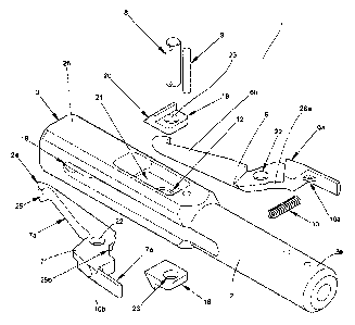
Figure 1 is an exploded view of an arrangement according to the invention
comprising an
overshot 1 to be used like a fishing system to grab a head assembly. This will
be described
in detail below.
The overshot 1 (Figure 2) comprises a first part with an elongated body 2
adapted to be
connected to a hoisting line in one end 2a and with an axial tubular opening
in the other
end 2b arranged to receive a spearhead 4 (Figure 7). The overshot 1 further
comprises a
second part with a scissor like mechanism 5 comprising two lifting dogs 6, 7
each
comprising a circular opening 22. A pivot pin 8 is arranged through the
openings 22 such
that the lifting dogs are arranged to pivot around the common pivot pin 8
(Figure 3). Each
lifting dog 6, 7 comprise a lever portion 6a, 7a and a lifting portion 6b, 7b.
The lever
portions 6a, 7a are connected with a biasing means 10 in the form of a tension
spring 10a
attached between connection points 10a, 10b.
The elongated body 2 comprises a central, axially extending slot 12 and the
scissor like
mechanism 5 is arranged with the common pivot pin 8 sliding in the slot 12
(Figure 4).
The scissor like mechanism 5 is arranged to move during operation such that
the common
pivot pin 8 is sliding in the slot 12 between a first end position 13 and a
second end
position 14 (Figure 2).
CA 02763137 2011-11-22
WO 2010/145984 PCT/EP2010/058134
8
An area 21 around the slot 12 in the overshot body 2 (Figure 1) for the pivot
pin 8 is
machined to allow retaining bar or washer to slide with the pivot pin. This
area is also
machined big enough to allow clearance for the operator to easily hold the
pivot pin and a
control lever 18 in the top, open position to allow the release of the
spearhead 4.
The pivot pin 8 slides within the elongated body 2. In the first end position
13 (Figure 5),
the common pivot pin 8 is in its lowermost position in the slot 12. The
scissor like
mechanism 5 is locked gripping a spear head 4 received in the tubular opening
3 due to the
tension spring 10a forcing the lever portions 6a, 7a to close. In this first
end position 13,
the lifting portions 6b, 7b are mechanically contained within the body 2,
prevented from
opening and releasing the spearhead 4.
The lifting portions 6b, 7b of the lifting dogs are designed to grab onto the
spear head. To
limit the movement of the lifting dogs, the locking features 15 of the head
were designed
to contain the lifting portion of the lifting dogs within the interior of the
head throughout
the travel of the lifting dogs.
Manually holding the scissor like mechanism 5 against the opening means 9 in
the up/top
position will force the lifting dogs 6, 7 open and thus allowing the release
of the spearhead
4. To release the inner-tube from the overshot at the surface, the operator
has to push the
spear head inside the overshot and maintain the sliding bar in the up/top
position.
Alternatively, the tension of the lifting dogs is released on the spearhead to
start with and
then the operator has to push the sliding bar and maintain up a pin and
continue the
movement/pushing of the sliding bar 18 to up/top position. This is safe, easy
and quickly
done and improves the
Figure 6a is a cross section of an overshot arrangement according to the
invention in a
position between first 13 and second end positions 14 on the way of releasing
the head
assembly.
CA 02763137 2011-11-22
WO 2010/145984 PCT/EP2010/058134
9
In the second position 14 (Figure 6b), the common pivot pin 8 is in its
uppermost position
in the slot 12. The elongated body 2 is arranged to comprise an opening means
9 arranged
to force the two lever portions 6a, 7a away from each other in the second
position 14. The
opening means 9 is a pin 9a arranged stationary attached to the elongated body
2. The pin
9a is arranged in parallel with the common pivoting pin 8 (Figure 4).
The elongated body 1 further comprises a pair of elongated adjacent and
parallel side
openings 16, 17 arranged such that the lifting portions 6b, 7b can pass/exit
the inside walls
during pivoting of the lifting dogs 6, 7 to an open position.
Each lifting dog 6, 7 comprise a sliding surface curvature 26a, 26b which is
arranged to
follow/slide along the stationary opening pin 9a during the pivoting/pushing
(Figure 6a,
6b) to an open position. Thus, the scissor like mechanism 5 is open due to the
forced
pivoting of the lever portions 6a, 7a apart into the second position 14.
Consequently, a
spear head 4 received in the coaxial tubular opening 3 of the overshot is
released when the
pivot pin 8 is in the second position 14.
When the force is removed from the control lever 18, the force of the spring
10a will pull
the lifting dog lever portions 6a, 7a together and close the scissor like
mechanism 5, which
will move downwards partly due to the sliding surface curvatures 26a, 26b
leaving the
sliding contact with the pivot pin 8 and partly due to forces of gravity.
In each of the overshot arrangements in Figure 1-4, at least one control lever
18
comprising a circular opening 23 and a flat surface 20 is connected
to/arranged on the
pivot pin 8 for the manual operation of the overshot. The flat surface 20 is
adapted to be
the surface to touch during pushing.
The pin used as a pivot point for the lifting dogs are secured to the assembly
using cotter
pins and/or retaining rings at both end to facilitate ease of assemble and
reduction of tools
and parts.
CA 02763137 2011-11-22
WO 2010/145984 PCT/EP2010/058134
The slot has been designed into the overshot head to allow the pivot pin to
move
approximately 3/8" - 1/2". This movement allows the lifting dogs to move in
and out of the
locked position and interact with the slide pin as mentioned above.
5 Figure 7 is an arrangement with an overshot 1. The overshot 1 is connected
to an
underground adapter 27 comprising a propulsion seal 28 and support washer 29.
Figure 8 is an overshot 1 according to the invention adapted with pump-in
seals 30 to be
used in an underground application.
Figure 9 is an overshot 2 wherein the opening means 9 is a sliding opening pin
9b
arranged sliding in the slot 12 and connected to the pivot pin by a sliding
bar 19.
Figure 10 is a device comprising an alternative overshot device 30 comprising
a first part
with an elongated body 2 and a second part with a scissor like mechanism 31
comprising a
pivot pin 32. A protective ring 33 is arranged locking the overshot device 30
to help
prevent the lever portion of the lifting dogs from accidentally being forced
inwards.
In Figure 10, the scissor like mechanism 31 is in the open position.
The principle of operation of the alternative overshot 30 in Figure 10 is
adapted tom
operate in the same way as the one described above.
The overshot device 30 comprises a first lifting dog 34 (Figure lla-c)
comprising a lever
portion 34a and a lifting portion 34b. The lever portion 34a in turn comprises
a scissor
portion 34c and a connection point 36 to retain a compression spring. Further,
the lever
portion comprises an opening 38 arranged to receive the pivot pin 32.
The lifting dog 34 has a part 39 of less thickness than the rest of the
lifting dog (Figure
11a). The thickness H of the lifting (Figure 11c) is twice the thickness of
the lifting dog
part 39, comprising the opening 38. This provides the scissor like mechanism
31.
CA 02763137 2011-11-22
WO 2010/145984 PCT/EP2010/058134
11
Figure 12 is a cross section of an overshot arrangement according to the
invention, in a
first (closed) position as described above. A first lifting dog 34 and a
second lifting dog 35
are arranged pivoting around the common pivot pin 32. The pivot pin 32 slides
within the
elongated body 2, as described above. In a first end position (Figure 12), the
common pivot
pin 32 is in its lowermost position in the slot, as described above. The
scissor like
mechanism 31 is locked gripping a spear head (not shown) received in the
tubular opening
40 due to the spring means 41 forcing the lifting portions 34b, 35b to close.
In this closed
position, the lifting portions 34b, 35b are mechanically contained within the
body 2,
prevented from opening and releasing a spearhead.
Figure 13 is a cross section of an overshot arrangement according to the
invention in a
second (open) position, as described above. In this open position, the common
pivot pin 32
is in its uppermost position in the slot.
Manually holding the scissor like mechanism 31 against the opening means 9 in
the up/top
position will force the lifting dogs 34b, 35b open and thus allowing the
release of a
spearhead 42.
In the overshot device in Figure 10-13, the spring biasing means comprises a
compression
spring 41 attached between the two lever portions 34a, 35a and connected in a
first 36 and
a second connection point 37. The compression spring 41 is adapted to force
the first
scissor portion 34c and the second scissor portion 35c apart and consequently
forcing the
first 34b and the second lifting portion 35b towards each other to a closed
gripping
position.
As described above, manually holding the scissor like mechanism 31 against the
opening
pin 9 in the up/top position will compress the compression spring 41. This in
turn causes
the first scissor portion 34c and second scissor portion 35c to pivot apart
and the first 34b
and the second lifting portion 35b pivot apart.
The first lifting dog 34 comprises a scissor portion 34c comprising a surface
curvature 43
with a sliding surface 43a (Figure 11b). The second lifting dog 35 comprises a
scissor
CA 02763137 2011-11-22
WO 2010/145984 PCT/EP2010/058134
12
portion 35c comprises in the same way a surface curvature 44 comprising a
sliding surface
44a (Figure 12). The sliding surfaces 43a, 44a are arranged to follow/slide
along the
stationary opening pin 9a during the pivoting/pushing (Figure 13) to an open
position.
Thus, the scissor like mechanism 31 is opened due to the forced pivoting of
the two scissor
portions 34a, 35a apart. Consequently, a spear head 41 received in the coaxial
tubular
opening 40 of the overshot is released when the pivot pin 32 is in its
uppermost position,
the second position as described above.
The method of operating an overshot will be explained in the following. The
overshot 1,
30 is arranged hanging in a hoisting line (not shown), is lowered down in a
drilled hole like
a fishing system to grab a spearhead assembly connected to an inner tube. In
this position,
the scissor like mechanism 5, 31 is closed due to the spring's action 10a, 40.
When the
overshot 2 reaches the spearhead 4, the spearhead is free to pass into the
coaxial tubular
opening 3 of the overshot. The overshot is designed such that the weight of
the elongated
body 2a, i.e. the gravity forces keeps the elongated body hanging down while
the
spearhead 4, 41 pushes the scissor like mechanism 5 in the opposite direction,
up in e.g.
Figure 3. The forced pushing upwards makes the opening means i.e. the
stationary pin 9a
forcing the lifting dogs 6, 7; 34, 35 to pivot into an open position where the
spearhead 4,
41 is passing in between the lifting portions 6b, 7b; 34b, 35b. In this
position the forced
pushing upwards is ended, the scissor like mechanism is sliding/falling back
downwards.
During this sliding/falling back, the lifting dogs are automatically pivoting
back into the
closed position and the head 4 is automatically locked. The lifting portions
6b, 7b; 34b,
35b of the lifting dogs are designed with a curve wrap 24 (Figure 1, 1 lb)
around the neck
to wrap around the neck of the spearhead, increasing the gripping of the
spearhead. The
lifting dogs also have curvature 25 (Figure 1, 12) on the outside surface to
interact with
the matching curved features 15 within the overshot (Figure 3, 12) to reduce
wear and
improve the distance required to lock the lifting dogs 6, 7; 34, 35 within the
overshot head
1.
When the overshot and the back end or head assembly are connected for the core
recovery,
the overshot is gripping and the head 4, 42 is in this way/moment locked.
CA 02763137 2011-11-22
WO 2010/145984 PCT/EP2010/058134
13
When it is time to release the inner-tube at the surface from the overshot,
the operator has
to push the spear head 4 inside the overshot 1 and maintain up the pivot pin 8
with the
control lever 18 to up/top position. Alternatively, the tension of the lifting
dogs is released
on the spearhead to start with and then the operator has to maintain up the
pivot pin 8 and
push the control lever 18 to up/top position.
During the pushing movement, the scissor like mechanism 5 is pushed upwards
with the
pivot pin 8 sliding in the slot 12. The design of the overshot device 1 is
based on the
requirement that the mentioned manual pushing upwards of the pivot pin makes
the lifting
dogs 6, 7 pivoting. This is achieved due to the scissor like design with a
common pivot pin
8 and of each lever portions 6a, 7a of the lifting dogs comprising a curvature
surface 26a,
26b adapted to slide along the stationary pin 9a during the operators pushing
of the control
lever 18. When the manual pushing upwards overcomes the tension force of the
tension
spring 10a, the pushing and the design of the curvature surfaces 26a, 26b in
combination
1 5 with the stationary pin 9a forces the lever positions 6a, 7a to pivot
apart. Consequently, the
scissor like mechanism 5 is forced open and the spear head 4 is released.
Alternatively, during the pushing movement, the scissor like mechanism 31 is
pushed
upwards with the pivot pin 32 sliding in the slot (not shown). The design of
the overshot
device 30 is based on the requirement that the mentioned manual pushing
upwards of the
pivot pin makes the lifting dogs 34, 35 pivoting. This is achieved due to the
scissor like
design with a common pivot pin 32 and of each lever portions 34a, 35a of the
lifting dogs
comprising a curvature surface 43a, 44a adapted to slide along the stationary
pin 9a during
the operators pushing of the control lever 46 (Figure 10). When the manual
pushing
upwards overcomes the compression force of the compression spring 41, the
pushing and
the design of the curvature surfaces 43a, 44a in combination with the
stationary pin 9a
forces the scissor portions 34c, 35c to pivot apart. Consequently, the scissor
like
mechanism 31 is forced open and the spear head 42 is released.
The first scissor portion 34c comprises an outer surface 44 (Figure 11a),
which faces
towards the lever portion 35a of the second lifting dog 35 when comprised in
the scissor
like mechanism 31. In the same way, the second scissor portion 35c comprises
an outer
CA 02763137 2011-11-22
WO 2010/145984 PCT/EP2010/058134
14
surface 45 (Figure 12), which faces towards the lever portion 34a of the first
lifting dog 34
when comprised in the scissor like mechanism 31.
When after pivoting, the scissor like mechanism 31 reaches its open position,
the first outer
surface 44 will be positioned adjacent the second lever portion 35a and the
second outer
surface 45 will be positioned adjacent the first lever portion 34a.
If the pivoting movement continues, the outer surfaces will get in contact
with respective
lever portion and stop the pivoting, as a secondarily purpose. In that way,
the pivot
movement is limited
To limit the movement of the lifting dogs, the locking features of the head
are designed to
contain the lifting portion of the lifting dogs within the interior of the
head throughout the
travel of the lifting dogs.