Note: Descriptions are shown in the official language in which they were submitted.
CA 02763279 2012-01-06
Title
METHOD FOR BONDING PLASTIC MOLD MEMBER ONTO METAL HOUSING
Background of the Invention
1. Field of the Invention
The present invention relates to a method for fabricating a metal-plastic
composite body,
and more particularly, to a method for bonding plastic mold members onto a
metal housing.
2. Description of the Prior Art
In recent years, metal housings with lightweight and high rigidity properties
have
become more and more necessary since the portable electronic products are
developed to be
more and lighter, shorter and smaller. In order to follow such requirements,
the technology of
composite material that combines metal housing with plastic mold members has
become a
main focus in the industry. The conventional method for fabricating the above-
mentioned
composite article may comprise the steps of molding the metal piece and the
plastic piece
separately, applying an adhesive on the metal piece, and then stacking and
bonding the metal
piece and plastic piece together by pressing. However, the metal housing used
in 3C product
is usually provided with irregular curved surfaces rather than simple plane
structures, and the
plastic piece may also have corresponding curved surfaces. It is very
difficult for two curved
surfaces to bond each other, thereby hindering the yield enhancement.
In relevant prior art, a method for tightly bonding carbon fiber reinforced
plastic (CFRP)
pre-preg with a metal alloy is disclosed in Japanese Patent Publication No.
2011-73191.
Please refer to FIG. 1, the method comprises: roughening predetermined
surfaces of CFRP
pre-preg 12 and metal alloy 11 first, and applying respectively a one-pack
type epoxy
adhesive on the roughened surface. Then, the both surfaces covered with the
epoxy adhesive
are contacted, cured and bonded with each other, wherein a particular chemical
agent is
necessary for the roughening of the predetermined surface of metal alloy 11 in
order to form a
surface with nanopores.
A method for fabricating a composite body comprised of metal alloy and
thermosetting
resin is disclosed in Japanese Patent Publication No. 2010-274600. Please
refer to FIG2, the
method comprises: applying particular chemical agent on a metal alloy body I
to form a
surface with nanopores, and then forming a surface layer made of metal oxide
or metal
phosphides. Final, forming a plastic member 4 on the surface of metal alloy
body 1 by insert
injection molding process.
CA 02763279 2012-01-06
A method of fabricating buttons is disclosed in Japanese Patent Publication
No.
2007-179952. The method features the following steps: bonding a metal coating
of an outer
key top piece and a white coating of an inner key top piece via a fusion
layer.
A method for fabricating push-buttons is disclosed in Japanese Patent
Publication No.
2009-81030. In this method, the adhesive used for bonding the cover member and
key top is
applied in dot array between said cover member and said key top in order to
facilitate the
degassing process during the fabrication.
A metal surface treatment method is disclosed in China Patent Publication No.
1827839.
The method comprises: applying a primer first, coating a metal film by vacuum
deposition,
and then spray a transparent hard film on a metal piece for protection. The
purpose of said
method is to fabricate the Mg alloy product with a metal texture by surface-
treating a raw
piece of Mg alloy via vacuum deposition process.
A method of fabricating metal-resin composite articles by injection molding is
disclosed
in Japanese Patent Publication No. 2011-11505. Please refer to FIG.3, the
resin part 30 is
molded on the rear of a metal body 20 and the surface of the metal body 20 is
decorated by a
decorative sheet F simultaneously with the molding of the resin part 30.
A method of fabricating composite articles is disclosed in Japanese Patent
Publication
No. 2011-11505. The method comprises: forming a decorative sheet on one
surface of a metal
body simultaneously with the injection of a molten resin, thereby forming a
composite article
comprised of the metal body and injected resin in desired mold shape.
Please refer to FIG.4, a method of fabricating a resin molding equipped with
transparent
insert material is disclosed in Japanese Patent Publication No. 2011-73314 to
provide a resin
molding in which strength of a resin part is improved. The method comprises:
providing a
metallic frame material 4 arranged on the outer periphery of the insert
material 3, and sticking
an adhesive sheet 5 on the reverse side over the insert material 3 and the
frame material 4. A
resin part 7 is then formed around the insert material 3 and engaging with at
least a part of the
periphery 4A of the frame material 4 by injection molding.
Summary of the Invention
The main purpose of the present invention is to provide a method for bonding a
plastic
member onto a metal housing in order to overcome the shortcomings and
disadvantages in
prior art.
According to one preferred embodiment of the present invention, a method for
bonding a
plastic member onto a metal housing is provided, comprising the steps of.
preparing a metal
housing having an inner surface and an outer surface; subjecting the metal
housing to a
2
CA 02763279 2012-01-06
physical processing, thereby forming a bonding area on the inner surface;
forming an
adhesive layer on the bonding area; and subjecting the metal housing to a
plastic injection
molding, thereby bonding a plastic mold member on the adhesive layer.
These and other objectives of the present invention will no doubt become
obvious to
those of ordinary skill in the art after reading the following detailed
description of the
preferred embodiment that is illustrated in the various figures and drawings.
Brief Description of the Drawings
The accompanying drawings are included to provide a further understanding of
the
embodiments, and are incorporated in and constitute a part of this
specification. The drawings
illustrate some of the embodiments and, together with the description, serve
to explain their
principles. In the drawings:
FIG 1 is a schematic view of a carbon fiber reinforced plastic pre-preg
tightly bonded to
a metal alloy disclosed in Japanese Patent Publication No. 2011-73191.
FIG .2 is a schematic view of a composite comprised of metal alloy and
thermosetting
resin disclosed in Japanese Patent Publication No. 2010-274600.
FIG .3 is a schematic view of a metal-resin composite fabricated by injection
molding
disclosed in Japanese Patent Publication No. 2011-11505.
FIG4 is a schematic view of a resin molding method using transparent inserting
materials disclosed in Japanese Patent Publication No. 2011-73314.
FIG .5 is a side view of a composite body with plastic members bonded on a
metal
housing exemplified in the present invention.
FIG6 is a cross-sectional view of the composite body with plastic members
bonded on a
metal housing in FIGS taken along the line I-I'.
FIG.6A is an enlarged view of the portion in circle of FIG6.
FIG .7 is a flowchart of the method for fabricating a composite body with
plastic
members bonded onto a metal housing according to one preferred embodiment of
the present
invention.
FIG.8 is a flowchart of the method for fabricating a composite body with
plastic
members bonded onto a metal housing according to another preferred embodiment
of the
present invention.
It should be noted that all the figures are diagrammatic. Relative dimensions
and
proportions of parts of the drawings have been shown exaggerated or reduced in
size, for the
sake of clarity and convenience in the drawings. The same reference signs are
generally used
3
CA 02763279 2012-01-06
to refer to corresponding or similar features in modified and different
embodiments.
Detailed Description
In the following detailed description of the invention, reference is made to
the
accompanying drawings which form a part hereof, and in which is shown, by way
of
illustration, specific embodiments in which the invention may be practiced.
These
embodiments are described in sufficient detail to enable those skilled in the
art to practice the
invention. Other embodiments may be utilized and structural, logical, and
electrical changes
may be made without departing from the scope of the present invention.
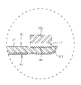
Please refer to FIGs.5, 6 and 6A, wherein FICI5 is a side view of a composite
body with
plastic members bonded on a metal housing, FIG.6 is a cross-sectional view of
the composite
body with plastic members bonded on metal housing in FIGS taken along the line
I-I', and
FIG. 6A is an enlarged view of the portion in circle in FIG.6. The composite
body with plastic
members bonded on a metal housing may be a cell phone housing or a battery
cover. As
shown in FIGs. 5 and 6, the composite body 1 with plastic members bonded on a
metal
housing of the present invention includes a metal housing 10 and a plastic
mold member 12
formed on the inner surface Si of the metal housing 10, wherein the plastic
mold member 12
is comprised of input/output jacks 12a, assembly structures 12b and/or
reinforcement
structures 12c.
The plastic mold member 12 is injection-molded on a bonding area SB in one
inner
surface Si of the metal housing 10. To be more specific, the bonding area SB
is formed by
physical processing or chemical processing before performing the inject-
molding of bonding
area SB. The plastic mold member 12 is inject-molded on an adhesive layer 112,
thereby
establishing a tight bonding with the metal housing 10. A decorating layer 101
may also be
coated on an outer surface So of the metal housing 10 to render various
textures and
appearances.
The above-mentioned physical processing for forming the bonding surface SB may
include roughening treatment by sandblast, laser etching, plasma treatment, UV
plasma
treatment, or die pressing, while the chemical processing may include chemical
etching and
shaping.
Please refer to FIG.7, which is a flowchart of the method for fabricating a
composite
body with plastic members bonded on a metal housing according to one preferred
embodiment of the present invention. As shown in FIG.7, the method for
fabricating a
composite body with plastic members bonded on a metal housing comprises two
sub-flows
4
CA 02763279 2012-01-06
S100 and S102, wherein the sub-flow S100 is the fabricating flow for the metal
housing,
while the sub-flow 5102 mainly comprises the steps of insert injection
molding, surface
finishing or treatment, and quality inspection for back-end product. First, a
feeding step and
an incoming inspection for metal material are performed (step M01), wherein
the foregoing
metal material may be stainless steel, Mg alloy, Al alloy or Mg-Al alloy.
Then, a
punch-shaping to obtain the desired shape of metal housing is performed (step
M02), wherein
the shape can be that of a cell phone housing or a battery cover. Then, a
milling process (step
M03) and a deburring process (step M04) are performed.
After the deburring process, a bonding area is formed on the inner surface of
metal
housing (step M05). According to one preferred embodiment of the present
invention, the
bonding area may be subjected to a surface treatment by physical processing,
such as
sandblast. Of course, other physical processes, like laser etching, plasma
treatment, UV
plasma treatment or die molding, may also be utilized to obtain roughened
surface.
Alternatively, the bonding area may also be formed by chemical processing,
such as chemical
etching and shaping. Then, a cleaning process (step M06) and a process for
coating adhesive
(step M07) are performed. The adhesive coating or adhesive bonding primers can
be formed
on the surface-treated bonding area by a spraying, a dispensing or a printing
method to form
an adhesive layer on said bonding area. A baking process is finally performed
(step M08).
This way the sub-flow S 100 is completed. The metal housing treated by the sub-
flow S 100 is
ready to undergo the following steps of insert injection molding (i.e. sub-
flow 5102).
The sub-flow S102 will be described hereinafter. First, a feeding step and an
inspection
step for a plastic material are performed (step P01), wherein the plastic
material may be
polycarbonate (PC) resin, acrylonitrile butadiene styrene (ABS) resin or
polyphenylene
sulfide (PPS) resin, etc. A drying process (step P02) is performed followed by
an insert
injection molding process to injection-mold the plastic material or plastics
on the metal
housing treated by sub-flow S100 (step P03). To be more specific, the plastic
is
injection-molded directly on the adhesive layer in the bonding area of the
metal housing. For
example, the metal housing can be a cell phone housing or a battery cover,
while the
injection-molded plastic mold members may be input/output jacks, assembly
structures and/or
reinforcement structures. Since the insert injection molding is a well-known
process, the
relevant details are omitted herein for simplicity. Then, perform a deburring
process (step P04)
and a surface finish step may be optionally carried out (step P05), such as
sandblast, hair-line
surface treatment, physical vapor deposition (PVD) process, anodic treatment
or spray
treatment, etc. Please note that the foregoing PVD treatment further includes
a Ni-plating
process which may provide the special effect of rendering concealed characters
on the surface
CA 02763279 2012-01-06
of housing. In addition, a decorating layer may be formed on the outer surface
of the metal
housing by printing, coating, or anodized aluminum treatment to render various
colors,
patterns and texture designs. Finally, perform a shaping step (step P06) and a
back-end quality
control step (step P07), thereby completing the sub-flow 5102.
Please refer to FIG 8, which is a flowchart of the method for fabricating the
composite
body with plastic members bonded to metal housing according to another
preferred
embodiment of the present invention. As shown in FIG8, the method for
fabricating a
composite body with plastic members bonded to a metal housing comprises also
two
sub-flows S200 and S202, wherein the sub-flow S200 is a fabricating flow for
the metal
housing, while sub-flow S202 mainly comprises the steps of insert injection
molding, surface
treatment and quality inspection for the back-end product. The sub-flow S202
will be
described hereinafter. First, perform a feeding step and an incoming
inspection for the metal
material (step M11), wherein the metal material may be stainless steel, Mg
alloy, Al alloy or
Mg-Al alloy, etc. Then, form a bonding area on the inner surface of the metal
housing (step
M12). According to one preferred embodiment of the present invention, the
bonding area may
be subjected to a surface roughening treatment by physical processing, such as
sandblast.
Other physical processes, for example, laser etching, plasma treatment, UV
plasma treatment
or die molding, may also be utilized to obtain the roughened surface. The
bonding area may
also be formed by a chemical processing, such as chemical etching and shaping.
Then,
perform a punch-shaping to obtain desired shape for the metal housing (step
M13), such as a
cell phone housing or a battery cover shape. Then, perform a milling process
(step M14) and a
deburring process (step M15). Then, perform a cleaning process (step M16).
After the cleaning process, a surface finish step is then performed (step
M17), such as
sandblast, hair-line surface treatment, PVD process, anodic treatment or spray
treatment, etc.
Please note that the foregoing PVD treatment further includes a Ni-plating
process which may
provide a special effect of rendering the concealed characters on the surface
of housing. In
addition, a decorating layer may be formed on the outer surface of the metal
housing by
printing, coating, or anodized aluminum treatment to render various colors,
patterns and
texture designs. Then, perform a process for coating adhesive (step M18), for
example,
coating the adhesive or adhesive bonding primers on the surface-treated
bonding area by a
spraying, a dispensing or a printing method to form an adhesive layer on said
bonding area.
Then, perform a baking process (step M19), thereby completing the sub-flow
S200. The metal
housing treated by the sub-flow S200 is ready to undergo the following insert
injection
molding (i.e. sub-flow S202).
The sub-flow S202 will be described hereinafter. First, perform a feeding step
and an
6
CA 02763279 2012-01-06
inspection step for a plastic material (step P11), wherein the plastic
material may be
polycarbonate (PC) resin, acrylonitrile butadiene styrene (ABS) resin or
polyphenylene
sulfide (PPS) resin, etc. Perform a drying process (step P12) and an insert
injection molding
process (step P13) to inject-mold the plastic material or plastics on the
metal housing
previously treated by sub-flow S200. To be more specific, the plastic is
inject-molded directly
on the adhesive layer in the bonding area of the metal housing. For example,
the metal
housing maybe a cell phone housing or a battery cover, while the injection-
molded plastic
mold members may be input/output jacks, assembly structures and/or
reinforcement structures.
Since the insert injection molding is a well-known process, the relevant
details are omitted
herein for simplicity. Then, perform a deburring process (step P14). Finally,
perform a
shaping step (step P15) and a back-end quality control step (step P16),
thereby completing the
sub-flow S202.
Those skilled in the art will readily observe that numerous modifications and
alterations
of the device and method may be made while retaining the teachings of the
invention.
Accordingly, the above disclosure should be construed as limited only by the
metes and
bounds of the appended claims.
7