Note: Descriptions are shown in the official language in which they were submitted.
,
CA 02763478 2011-11-24
,
1
Apparatus for therapeutically treating and/or training the
lower extremities of a person
Description
The invention relates to an apparatus for therapeutically
treating or training the lower extremities of a person.
An apparatus of this kind is known from DE 10 2006 035 715
Al, for example.
Therapy of severe weakness of the lower extremities, for
example following a stroke, is difficult and often
unsuccessful. Conventional physiotherapy is complicated and
in most cases is aimed at triggering spastically induced
muscle cramps and performing walking exercises when sitting
and standing, for example to strengthen the weight transfer
to the affected leg. This procedure often means that the
patient does not repeatedly practice walking and,
consequently, the foot and leg movements on which walking is
based.
Modern scientific concepts of rehabilitation favor repeated
and, if possible, active practice in walking as early as
possible, or, if this is not yet possible, the practice of
at least individual movement sequences of walking with the
feet and legs. For stroke patients, it has been possible to
show that repeated active, isometric and isotonic dorsal
extension of the feet and legs was superior to conventional
therapy as regards the recovery of the motor function of the
whole of the lower extremities. Still greater success was
able to be achieved if the patient practiced walking
repeatedly. Passive movements of paralyzed areas of the
extremities preserve, on the one hand, the mobility of the
CA 02763478 2011-11-24
2
movement segment and, on the other hand, the brain's recall
of the sequence of movement.
Bilateral exercising of the healthy side and of the weakened
side of the lower extremities is superior to unilateral
exercising of the weakened side. The associated movement of
the unweakened side has a positive influence on the
activation of the brain structures in the parietal lobe that
are responsible for the use of the paralyzed extremity.
For therapy of the healthy side and of the weakened side of
the lower extremities, the prior art discloses mechanical
and electro-mechanical appliances. In this connection,
reference is made to DE 36 18 686 Al, DE 85 28 083 Ul, DE 81
09 699 Ul and DE 195 29 764 Al, for example. These known
therapy appliances comprise pedals actuated by the patient.
These pedals permit only an asynchronous movement of the
weakened side. Asynchronous movements do not reflect the
variety of the real movement sequences. In this case, the
desired transfer of the learning effect in connection with
movement sequences from the brain lobe of the healthy side
to the affected side is possible only to a limited extent.
Variations of the movement sequences are ruled out because
of the rigid mechanical connection of the construction
elements.
Moreover, robotic systems for therapeutic purposes are
known which comprise control systems that measure the
strength of the patient during exercising. In these,
different evaluations of the parameters for determining
minimum spontaneous movements or forces and complete
comparisons with preset programs are possible. Such robotic
CA 02763478 2011-11-24
3
systems are known from DE 100 28 511 Al and from the
aforementioned DE 10 2006 035 715 Al.
In the robotic system according to DE 100 28 511 Al, the
degree of freedom for lateral pivoting of the foot plates is
not in itself necessary and, in addition, has proven
disadvantageous during exercising. The lateral pivoting of
the foot plates necessitates a complicated and protruding
structure, which makes access to the patient difficult for
the therapist. The robot-controlled run simulator known from
DE 10 2006 035 715 Al has proven capable of improvement in
terms of everyday suitability. Moreover, as is also the case
in the system according to DE 100 28 511 Al, access to the
patient is difficult.
The object of the invention is to create an apparatus for
therapeutically treating and/or training the lower
extremities of a person, with which apparatus it is possible
to simulate a wide variety of load situations that occur on
an everyday basis. The apparatus is intended to allow the
therapist easy access to the patient.
According to the invention, this object is achieved by the
apparatus as per claim 1.
The invention is based on the concept of creating an
apparatus for therapeutically treating and/or training the
lower extremities of a person, with driven controllable
motion devices, which are connected to a stationary frame,
and retaining means, which secure one extremity each. The
retaining means are movable independently of each other
along walking trajectories. The motion devices each have a
jib, which is pivotable to various heights and which, at one
CA 02763478 2011-11-24
4
end, is articulated on a first carriage of a linear guide
and, at the other end, is rotatably connected to one of the
retaining means. A second carriage of the linear guide is
arranged ahead of the first carriage in the walking
direction and is movable relative to the first carriage. The
second carriage of the linear guide is connected to the jib
in an articulated manner by a connecting element. The first
carriage has a first linear drive for changing the
longitudinal position of the respective retaining means, the
second carriage has a second linear drive for changing the
height of the respective retaining means, and the jib has a
rotary drive for changing the inclination of the respective
retaining means.
The invention has the advantage that the mechanics of the
motion devices have a simple and compact structure. Access
to the patient is in this way made easier for the therapist.
With the apparatus according to the invention, successful
therapy can be achieved on the one hand by frequent
repetition of training elements and on the other hand by the
transmission of learning effects from the side of the brain
responsible for the healthy extremity to the side or area of
the brain responsible for the weakened extremity. In
addition, the apparatus according to the invention permits
strengthening of the leg and back muscles in order to
further improve the state of a patient who has made progress
and in order to train healthy persons. The apparatus
according to the invention provides the condition for
permitting the training or walking therapy in an everyday
environment shown on a screen, the robust and simple
mechanics permitting simulation of different everyday
situations, for example climbing stairs, mounting a
pavement, or situations in which the patient stumbles.
,
. CA 02763478 2011-11-24
Preferred embodiments of the invention are set forth in the
dependent claims.
5 In one embodiment, the second linear drive comprises a
force-transmitting element that couples the two carriages.
The distance between the two carriages can be changed by
actuation of the force-transmitting element. The coupling of
the two carriages by a force-transmitting element has the
advantage that one of the two carriages, in particular the
second carriage, is carried along by the other carriage, in
particular the first carriage. The forward movement or the
horizontal movement of the motion device and therefore of
the retaining element are achieved together by the first
linear drive.
The second linear drive effects the relative movement
between the two carriages. The force-transmitting element in
this case has a dual function, on the one hand of carrying
the second carriage along by the movement of the first
carriage, and thus serves as a mechanical connection between
the two carriages. On the other hand, the force-transmitting
element provides the force needed for the relative movement
of the two carriages. For this purpose, the force-
transmitting element has its own drive. This embodiment has
the advantage that the drives and associated carriages can
be made comparatively small, such that it is possible to
achieve rapid changes of movement or rapid accelerations and
decelerations.
The second linear drive can comprise a rotary spindle, which
is rotatably secured at one end on the first carriage and at
the other end on the second carriage. The spindle drive of
CA 02763478 2011-11-24
6
the rotary spindle can be secured on the second or the first
carriage. This simplifies the structure of the apparatus.
The first linear drive can comprise a force-transmitting
element, which couples the first carriage to the stationary
frame. The first linear drive can comprise a driven chain,
which is secured at one end on the first carriage and at the
other end on the frame, as a result of which the horizontal
movement of the first carriage and therefore also of the
second carriage is achieved in a simple way.
The rotary drive for changing the inclination can be
arranged at a distance from the retaining means and can be
coupled to the latter by a force-transmitting means. In this
way, the rotary drive can be arranged at a favorable
position for the center of gravity. The rotary drive can
expediently comprise a belt, which is arranged on a driving
disk on the jib and on a driven disk on the retaining
element.
The above-described arrangements of the respective drives
permit, in each case individually and in combination with
each other, a simple structure of the respective motion
device, which takes up a small amount of space.
A longitudinal end of the jib is preferably articulated on
the first carriage. The connecting element can engage on the
jib between the articulation point on the first carriage and
the retaining element. This permits in each case a favorable
torque transmission from the respective drives to the jib
and thus to the retaining means.
CA 02763478 2011-11-24
7
In a preferred embodiment of the invention, an adjustment
device is arranged above the motion device and is designed
to change the center of gravity of the body of a person
connected to the retaining means. This embodiment has the
advantage that the adjustment device permits control of the
center of gravity of the body of a patient. In this way, it
is possible, on the one hand, to simulate the center-of-
gravity shift that occurs during human locomotion, i.e.
during forward movement, and that takes place along the
direction of movement in the vertical and lateral
directions. On the other hand, by means of controlling the
center of gravity, the correct execution of the therapeutic
movement is permitted, and it is thus possible to avoid
postural damage caused by compensatory movements of the
patients. A further advantage of controlling the center of
gravity of the body is that the equilibrium can be
maintained in critical situations, such as (simulated)
stumbling, slipping, or under conditions in which the
proprioceptive component is disturbed. Repeated practice of
these situations is necessary in order to minimize the risk
of the patients falling. The three-dimensional control of
the center of gravity, permitted in this embodiment, and the
option of influencing the proprioceptive component of the
patients by perturbations, create the conditions for safe,
repeatable and targeted training. The perturbations of the
proprioceptive component are provided by the retaining
means, in particular the foot plates, which are connected to
the feet of the patients. These can be moved to any desired
position along the three degrees of freedom. In addition,
vibrations can be provided by the retaining means.
CA 02763478 2011-11-24
8
The invention is explained in more detail below on the basis
of illustrative embodiments and with reference to the
attached schematic drawings, in which:
Fig. 1 shows a perspective view of an apparatus in one
illustrative embodiment according to the invention;
Fig. 2 shows a side view of the apparatus according to Fig.
1;
Fig. 3 shows a side view of the motion devices of the
apparatus according to Fig. 1;
Fig. 4 shows a plan view of the apparatus according to Fig.
1; and
Fig. 5 shows a perspective view of a retaining means of the
apparatus according to Fig. 1.
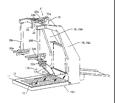
In Fig. 1 an apparatus is shown that can be used for
therapeutically treating and/or training the lower
extremities of a person. The apparatus is particularly well
suited for training the lower extremities of neurological
patients and has two driven controllable motion devices 10a,
10b. The two motion devices 10a, 10b are each connected to a
stationary frame 11. The motion devices 10a, 10b have
retaining means 12a, 12b, for example foot plates with
bindings in which the feet of the patients or of the persons
training are held. The motion devices 10a, 10b and therefore
the retaining means 12a, 12b can be moved independently of
each other along walking trajectories. Asynchronous or
synchronous movements are possible.
CA 02763478 2011-11-24
9
The apparatus comprises a stand 28 from which the patient is
suspended for weight relief and which is fixedly connected
to the frame 11. The stand 28 comprises two arms 28a, 28b,
which extend forward in the sagittal direction, wherein the
arms 28a, 28b reach approximately as far as the height of
the motion devices 10a, 10b and engage over these. At the
front end of the arms 28a, 28b, vertically arranged
connecting elements 29a, 29b are provided which connect the
arms 28a, 28b to side spars 30a, 30b. The side spars 30a,
30b are arranged approximately at the height of the forearms
of the respective patient and are vertically adjustable. The
side spars 30a, 30b serve as grips for patients, who are
able to hold onto the side spars 30a, 30b for support.
The motion devices 10a, 10b each have a jib 13, which is
pivotable to different heights. For this purpose, the jib 13
is articulated pivotably on a first carriage 14, which is
guided in a linear guide 15. The linear guide 15 is fixedly
connected to the stationary frame 11 and forms a rail in
which the carriage 14 is movably arranged. As can be seen in
Fig. 3, the jib 13 is articulated at a first longitudinal
end 13a on the first carriage 14. For this purpose, a first
rotary bearing 13b is provided, which connects the jib 13 to
the first carriage 14 in a pivotable manner. The first
rotary bearing 13b can be arranged at another place on the
jib 13, for example at a distance from the longitudinal end
13a.
The jib 13 is in each case connected rotatably to one of the
retaining means 12a, 12b. The connection point between the
retaining means 12a, 12b and the jib 13 is located at the
other, second longitudinal end 13c of the jib 13 and has a
' CA 02763478 2011-11-24
second rotary bearing 13e at a distance from the first
rotary bearing 13b.
The jib 13 forms a pivot arm extending in the longitudinal
5 direction of the respective linear guide 15.
A second carriage 16, which is guided movably in the linear
guide 15, is arranged ahead of the first carriage 14 in the
walking direction, i.e. in the direction of the forward
10 movement of the patient during use. The second carriage 16
is movable relative to the first carriage 14, such that the
distance between the two carriages 14, 16 can be changed. As
can be seen in Fig. 3, the second carriage 16 is connected
to the jib 13 in an articulated manner by a connecting
element 17. The connecting element 17 can, for example,
comprise one linking rod or two linking rods arranged in
parallel alongside each other. Other connecting elements 17
are possible. The connecting element 17 engages at one end
on a bearing block 16a of the second carriage 16 and at the
other end on the jib 13 between the articulation point 27 on
the first carriage 14 and the retaining element 12a, 12b.
The connecting element 17 is connected to the second
carriage 16 and to the jib 13 by two rotary bearings 17a,
17b. The rotary bearing 17b in the jib 13 is arranged
approximately centrally between the articulation point 13d
on the first carriage 14 and the retaining element 12a, 12b.
Another arrangement of the rotary bearing 17b on the jib 13
is possible, in particular an eccentric arrangement.
Generally, the connecting element 17 is articulated on the
jib 13 in an area or at a location that is arranged between
the connection of the jib 13 to the first carriage 14 and
CA 02763478 2011-11-24
11
the connection of the jib 13 to the retaining means 12a,
12b.
The connecting element 17 and the jib 13 form, together with
the first and second carriages 14, 16, a kind of scissor
mechanism. The angle between the jib 13 and the connecting
element 17 is changed by the relative movement of the two
carriages 14, 16 to each other. As is shown in Fig. 3 with
reference to the two jibs 13, a reduction of the angle, i.e.
a reduction of the distance between the two carriages 14,
16, has the effect that the jib 13 is moved upward, the
retaining means 12a, 12b describing a circular trajectory
about the articulation point 13d of the jib 13 on the first
carriage 14 or generally about a horizontal axis extending
transversely with respect to the walking direction. This
changes the height of the second longitudinal end 13c of the
jib 13 and, consequently, of the retaining means 12a, 12b
connected to the second longitudinal end 13c.
On account of the jib 13 being articulated on the first
carriage 14, the jib 13 is carried along, together with the
first carriage 16, by a movement of the first carriage 14,
as a result of which the horizontal movement of the whole
motion device 10a, 10b is achieved.
The first carriage 14 can also be designated as main
carriage, and the second carriage 16 as relative carriage.
As can be seen in Figures 3 and 4, the first carriage 14 has
a first linear drive 18, which is provided for changing the
longitudinal position or horizontal position of the
respective retaining means 12a, 12b. The first linear drive
18 comprises a first force-transmitting means 21a, which
CA 02763478 2011-11-24
12
connects the first carriage 14 to the stationary frame 11
for force transmission. The first force-transmitting means
21a can comprise a driven chain 24, which is connected at
one end to the movable carriage 16 and at the other end to
the stationary frame 11. An electric motor is provided for
driving the chain 24. The first linear drive 18 can also be
embodied by different means, for example by a toothed rack
or by hydraulic or pneumatic cylinders.
The second linear drive 19 is assigned to the second
carriage 16 and couples the latter to the first carriage 14.
For this purpose, a second force-transmitting element 21b is
provided, which engages at one end on the first carriage 14
and at the other end on the second carriage 16. The second
force-transmitting element has the function of ensuring that
the second carriage 16 is carried along in a movement of the
first carriage 14. The second force-transmitting element 21b
acts as a pushing and pulling element. In addition, by means
of the second force-transmitting element 21b, a force can be
transmitted from the second carriage 16 to the first
carriage 14 or vice versa, when the second force-
transmitting element 21b is actuated. The distance between
the two carriages 14, 16, and therefore the height of the
jib 13, is changed in this way.
The second linear drive 19 acts generally as a relative
drive between the two carriages 14, 16, wherein one of the
two carriages 14, 16, in particular the first carriage 14,
forms an abutment, and the other carriage 14, 16, in
particular the second carriage 16, is movable relative to
the abutment, specifically by actuation of the second linear
drive 19. The first linear drive 18 forms a main drive,
which moves both carriages 14, 16 together with the second
ak 012763478 2013-08-15
13
linear drive 19 relative to the stationary frame 11. The
second linear drive 19, in particular the force-transmitting
element 21b, acts as a carrier that transmits the drive
force of the first linear drive 18 to the second carriage.
In addition, the second linear drive 19 acts as a relative
drive for the relative movement between the two carriages
14, 16, as has been described above.
The second force-transmitting element 21b can, for example,
comprise a rotary spindle 22, which is connected rotatably
to the first and second carriages 14, 16 and ensures the
forward movement of the second carriage 16. In the
illustrative embodiment according to Fig. 4, the spindle
drive 23 is secured on the second carriage 16 and is coupled
to the rotary spindle 22. It is also possible for the
spindle drive 23 to be secured on the first carriage 14.
Accordingly, the spindle nut of the spindle drive can be
arranged optionally on the first or on the second carriage
14, 16. Other force-transmitting elements are possible, for
example a toothed rack or hydraulic/pneumatic actuating
elements. The force-transmitting element 21b generally has a
dual function and serves both as a carrier and also for
changing the distance between the two carriages 14, 16.
By actuation of the second linear drive 19, the distance
between the two carriages 14, 16 is changed, as is shown in
Fig. 4. In the motion device 10a arranged to the right in
the forward direction, the two carriages 14, 16 are located
close to each other, with the rotary spindle 22 protruding
rearward beyond the frame 11. In this position, the jib 13
is arranged at the maximum height. With the rotary spindle
22 driven out to the maximum extent as shown in the left-
CA 02763478 2011-11-24
14
hand motion device 10b, the jib 13 is located at the lowest
height.
To adjust the inclination of the retaining means 12a, 12b, a
rotary drive 20 is provided, which cooperates with the
respective rotatably movable retaining means 12a, 12b. The
rotary drive 20 is arranged in the area of the articulation
point 13d. The connection of the rotary drive 20 to the
respective retaining means 12a, 12b is provided by a third
force-transmitting element 21c, for example in the form of a
belt 25. The belt 25 is arranged, at one end, on a driving
disk 26 on the jib 13 and, at the other end, on a driven
disk 27, which is connected to the retaining element 12a,
12b. Instead of the belt 25, other force-transmitting
elements 21c can be used that convert a translation movement
into a rotation movement, for example a toothed rack that
meshes with a pinion on the retaining means 12a, 12b. The
inclination of the retaining means 12a, 12b is adjusted by
the rotary drive 20 and adapted to the respective position
of the jib 13. It is possible to variably set all the
possible inclination positions that are needed for
simulation of everyday situations.
The movement of the retaining means 12a, 12b takes place in
a work plane extending in the sagittal direction, wherein a
work space that has proven expedient permits the forward
movement in the range of 400 to 600 mm, particularly 550 mm,
the height movement in the range of 300 to 500 mm,
particularly 400 mm, and the pivoting movement of the
retaining means 12a, 12b in a range from -80 to +30 .
The pivoting movement of the retaining means 12a, 12b takes
place about a horizontally extending axis. The horizontally
CA 02763478 2011-11-24
extending axis is shifted in the horizontal and vertical
direction by the actuation of the two linear drives 18, 19.
To simulate everyday situations of human locomotion, the
5 retaining means 12a, 12b for the lower extremities, with the
patient standing on them and secured to them, can be
simulated both by programmed settings of the control and
also by the patient acting on resilient foot plates. It is
possible to change, as and when desired, between the
10 programmed movement and the movement guided by the patient.
Alternatively, one retaining means 12a can be controlled by
the patient and the other retaining means 12b by programmed
settings.
15 In the illustrative embodiment according to Fig. 1, an
adjustment device 31 is provided, which is arranged above
the motion devices 10a, 10b. The adjustment device 31 is
located above the linear guides 15, such that the motion
devices 10a, 10b, in particular the retaining means 12a,
12b, can be moved under the adjustment device 31. The
adjustment device 31 is designed to control the center of
gravity or to change the center of gravity of the body of a
person connected to the retaining means 12a, 12b. The
adjustment device 31 allows the center of gravity of the
body to be changed in the vertical direction and also in the
transverse direction. For this purpose, the adjustment
device 31 comprises a vertical drive 33a, which cooperates
with a strap 32. The strap 32 is connected to a patient-
supporting strap (not shown). The vertical drive permits a
change in the length of the vertical portion of the strap
32, such that the center of gravity of the patient can be
changed in the vertical direction. The work space of the
mechanism or of the adjustment device 31 for changing the
= CA 02763478 2011-11-24
16
center of gravity measures +/- 10 cm relative to a zero
position. Other ranges are possible. An example of the
design of the adjustment device 31 is shown in Fig. 1 and
can comprise a rotary drive, which is connected to a pivot
mechanism 33c. The pivot mechanism 33c shortens the
supporting strap of the patient via a roller system and thus
draws the center of gravity of the patient upward. A
lowering of the patient or lengthening of the strap 32 is
likewise possible.
The pivot mechanism 33c has a pivot arm on which three
rollers are secured. The rollers, in particular two end
rollers and a central roller arranged between the two end
rollers, serve to guide the strap 32 and form an arrangement
by which the center of gravity of the body of a patient can
be changed. Each one of the two end rollers is located at a
respective end of the pivot arm. The central roller is
arranged centrally at the rotation point or pivot point of
the pivot arm. The strap 32 extends from the patient lifter
35 over the first end roller, under the central roller and,
from there, over the second end roller through the pivot
mechanism to the patient strap. The vertical drive, in
particular the rotation drive 33a, effects a pivoting
movement about the rotation point of the pivot mechanism, in
particular of the pivot arm. In this way, the end rollers at
the end of the pivot arm are raised or lowered and thus
raise or lower the strap 32.
Other devices for raising and lowering the strap 32 are
possible.
CA 02763478 2011-11-24
17
The patient lifter 35 serves to lift the patient into the
treatment position or to lower the patient from the
treatment position after the treatment has ended.
To control the transverse component of the center of
gravity, a transverse drive 33b is provided, which has a
rotation drive connected to a disk 34. A rope (not shown) is
secured to the disk 34, the ends of the rope extending as
far as the patient. The rope is guided via a roller system
(not shown) and engages at both ends, for example by
carbines, on lateral eyelets of the patient strap. By
rotation of the disk 34, the patient is pulled in the
transverse direction by the shortening of one of the two
rope ends. A possible work space for the center-of-gravity
shift permitted by the transverse drive 33b measures, for
example, +/- 5 cm relative to a zero position. Other ranges
are possible.
The control of the center of gravity in the forward or
rearward direction is effected by the relative movement of
the retaining means 12a, 12b or of the foot plates relative
to the suspension point of the adjustment device 31. The
position of the first carriage 14 (main carriage) can be
controlled freely on the linear guide 15. The suspension
point of the patient is stationary in a direction parallel
to the linear guide 15, such that a corresponding shifting
of the center of gravity is possible. The work space allowed
by the carriage length measures +/- 10 cm relative to a zero
position. Other ranges are possible.
The apparatus permits extremely variable and flexible
therapy or training of the lower extremities, and the
CA 02763478 2011-11-24
18
apparatus has a simple and compact structure and thus
ensures easy access for the patient.
The following subject matter is disclosed as belonging to
the invention:
1. An apparatus for therapeutically treating and/or
training the lower extremities of a person, with driven
controllable motion devices (10a, 10b), which are connected
to a stationary frame (11), and retaining means (12a, 12b),
which secure one extremity each and are movable
independently of each other along walking trajectories,
wherein the motion devices (10a, 10b) each have a jib (13),
which is pivotable to various heights and which, at one end,
is articulated on a first carriage (14) of a linear guide
(15) and, at the other end, is rotatably connected to one of
the retaining means (12a, 12b),
characterized in that a second carriage (16) of the
linear guide (15) is arranged ahead of the first carriage
(14) in the walking direction, is movable relative to the
first carriage (14) and is connected to the jib (13) in an
articulated manner by a connecting element (17), wherein the
first carriage (14) has a first linear drive (18) for
changing the longitudinal position of the respective
retaining means (12a, 12b), the second carriage (16) has a
second linear drive (19) for changing the height of the
respective retaining means (12a, 12b), and the jib (13) has
a rotary drive (20) for changing the inclination of the
respective retaining means (12a, 12b).
2. The apparatus as per number 1,
characterized in that the second linear drive (19)
comprises a force-transmitting element (21b) that couples
CA 02763478 2011-11-24
19
the two carriages (14, 16), and the distance between the two
carriages (14, 16) can be changed by actuation of the force-
transmitting element (21b).
3. The apparatus as per number 1 or 2,
characterized in that the second linear drive (19)
comprises a rotary spindle (22), which is rotatably secured
at one end on the first carriage (14) and at the other end
on the second carriage (16).
4. The apparatus as per number 3,
characterized in that a spindle drive (23) of the
rotary spindle (22) is secured on the second or the first
carriage (14, 16).
5. The apparatus as per numbers 1 through 4,
characterized in that the first linear drive (18)
comprises a force-transmitting element (21a), which couples
the first carriage (14) to the stationary frame (11).
6. The apparatus as per at least one of numbers 1 through
5,
characterized in that the first linear drive (18)
comprises a driven chain (24), which is secured at one end
on the first carriage (14) and at the other end on the frame
(11).
7. The apparatus as per at least one of numbers 1 through
6,
characterized in that the rotary drive (20) for
changing the inclination is arranged at a distance from the
retaining means (12a, 12b) and is coupled to the latter by a
force-transmitting means (21c).
CA 02763478 2011-11-24
8. The apparatus as per at least one of numbers 1 through
7,
characterized in that the rotary drive (20) comprises a
5 belt (25), which is arranged on a driving disk (26) on the
jib (13) and on a driven disk (27) on the retaining element
(12a, 12b).
9. The apparatus as per at least one of numbers 1 through
10 8,
characterized in that a longitudinal end (13a) of the
jib (13) is articulated on the first carriage (14).
10. The apparatus as per at least one of numbers 1 through
15 9,
characterized in that the connecting element (17)
engages on the jib (13) between the articulation point (13d)
on the first carriage (14) and the retaining element (12a,
12b).
11. The apparatus as per at least one of numbers 1 through
10,
characterized in that an adjustment device (31) is
arranged above the motion device (10a, 10b) and is designed
to change the center of gravity of the body of a person
connected to the retaining means (12a, 12b).
CA 02763478 2011-11-24
21
List of reference signs
10a, 10b motion devices
11 frame
12a, 12b retaining means
13 jib
13a first longitudinal end
13b first rotary bearing
13c second longitudinal end
13d articulation point
13e second rotary bearing
14 first carriage
15 linear guide
16 second carriage
16a bearing block
17 connecting element
17a, 17b rotary bearing
18 first linear drive
19 second linear drive
20 rotary drive
21a, 21b, 21c force-transmitting element
22 rotary spindle
23 spindle drive
24 chain
25 belt
26 driving disk
27 driven disk
28 stand
28a, 28b arms
29a, 29b connecting elements
30a, 30b side spars
31 adjustment device
32 strap
. CA 02763478 2011-11-24
22
33a vertical drive
33b transverse drive
33c pivot mechanism
34 adjustment disk
35 patient lifter