Language selection

Search

Patent 2763660 Summary

Third-party information liability

Some of the information on this Web page has been provided by external sources. The Government of Canada is not responsible for the accuracy, reliability or currency of the information supplied by external sources. Users wishing to rely upon this information should consult directly with the source of the information. Content provided by external sources is not subject to official languages, privacy and accessibility requirements.

Claims and Abstract availability

Any discrepancies in the text and image of the Claims and Abstract are due to differing posting times. Text of the Claims and Abstract are posted:

  • At the time the application is open to public inspection;
  • At the time of issue of the patent (grant).
(12) Patent Application: (11) CA 2763660
(54) English Title: METHOD OF CREATING A CROSS-MACHINE DIRECTION FOLD LINE BOUNDARY
(54) French Title: METHODE DE CREATION D'UNE DEMARCATION DE LIGNE DE PLIAGE EN SENS TRAVERS
Status: Deemed Abandoned and Beyond the Period of Reinstatement - Pending Response to Notice of Disregarded Communication
Bibliographic Data
(51) International Patent Classification (IPC):
  • B29C 65/00 (2006.01)
  • A61F 13/15 (2006.01)
  • A61F 13/496 (2006.01)
(72) Inventors :
  • ANDREWS, ROBERT E. (United States of America)
(73) Owners :
  • CURT G. JOA, INC.
(71) Applicants :
  • CURT G. JOA, INC. (United States of America)
(74) Agent: LAVERY, DE BILLY, LLP
(74) Associate agent:
(45) Issued:
(22) Filed Date: 2011-12-30
(41) Open to Public Inspection: 2012-06-30
Examination requested: 2015-12-16
Availability of licence: N/A
Dedicated to the Public: N/A
(25) Language of filing: English

Patent Cooperation Treaty (PCT): No

(30) Application Priority Data:
Application No. Country/Territory Date
61/428,678 (United States of America) 2010-12-30

Abstracts

English Abstract


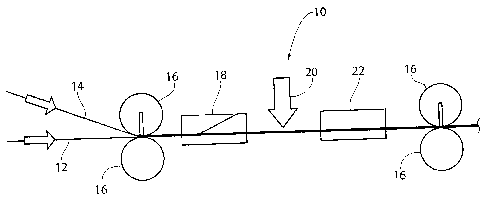
Apparatus and methods are provided to allow
for creation of a cross-machine direction fold
boundary, so that a laminate with a defined foldover
can be created. A laid open two-ply material can then
undergo processing operations such as addition of
discrete disposable product components, or printing,
and then be laid closed and sealed to form disposable
products.


Claims

Note: Claims are shown in the official language in which they were submitted.


-7-
I Claim:
1. A method of creating a machine direction
fold line comprising:
supplying a first and a second web both
running in a machine direction;
creating a first bond pattern between said
first and said second webs for a first distance in a
cross-machine direction, said first distance less than
a width of said first and second webs and defining a
fold line boundary;
folding over said second web to create a
machine direction fold line coextensive in the cross-
machine direction with said fold line boundary.
2. A method according to claim 1, wherein said
first bond pattern is intermittently applied in the
machine direction as said webs run.
3. A method according to claim 1, wherein said
first bond pattern is continuously applied in the
machine direction as said webs run.
4. A method according to claim 1, the method
further comprising creating a second bond pattern
between said first and said second webs.
5. A method according to claim 4, said second
bond pattern coextensive in the cross-machine direction
with said fold line boundary.
6. A method according to claim 4, said second
bond pattern not coextensive in the cross-machine
direction with said fold line boundary.

Description

Note: Descriptions are shown in the official language in which they were submitted.


CA 02763660 2011-12-30
Atty. Docket No.: 1047.2144.3-CA
- 1 -
Patent
METHOD OF CREATING A CROSS-MACHINE DIRECTION
FOLD LINE BOUNDARY
Related Application
This application claims the benefit of co-
pending U.S. Provisional Application Serial No.
61/428,678, filed 30 December 2010.
Background of the Invention
This invention relates to an apparatus and
method for creating a cross-machine direction fold line
boundary that can be used in production of disposable
absorbent articles.
Summary of the Invention
In order to present a two-ply material with
the plies spread open, two or more layers of material
can be laid on one another and bonded to one another
intermittently in the machine direction, at a
relatively short cross-machine direction dimension.
The top (or bottom) layers can then be folded over to
present a laid-open type presentation so that material
can be sandwiched between the plies, or other
processing operations could be performed on the
interior of the plies. In this manner, the bonding
(either intermittent in the machine direction, or
continuous down the length of the web in the machine
direction) of the plies creates a boundary in the

CA 02763660 2011-12-30
Atty. Docket No.: 1047.2144.3-CA
2 -
cross-machine direction, past which the fold cannot
proceed in the cross-machine direction.
Brief Description of the Drawings
Fig. 1 is a side view schematic of a
representative web processing system;
Fig. 2A is a perspective view of a two ply
material advancing in the machine direction, with
intermittent bonds extending partially across the plies
in the cross-machine direction;
Fig. 2B is a cross-sectional view of a two
ply material intermittently bonded;
Fig. 3A is a perspective view of a two ply
material advancing in the machine direction, with
intermittent bonds extending partially across the plies
in the cross-machine direction, the top ply having been
folded over in the cross-machine direction to the
intermittent bonds, the intermittent bonds creating a
boundary which the foldover cannot go past;
Fig. 3B is a cross-sectional view of the
product shown in Fig. 3A;
Fig. 4A is a perspective view of a two ply
material advancing in the machine direction, with
intermittent bonds extending partially across the plies
in the cross-machine direction, as well as coterminous
bonds extending widthwise in the cross machine
direction;
Fig. 4B is a cross-sectional view of the
product shown in Fig. 4A.
Description of the Preferred Embodiment
Although the disclosure hereof is detailed
and exact to enable those skilled in the art to
practice the invention, the physical embodiments herein
disclosed merely exemplify the invention which may be
embodied in other specific structures. While the

CA 02763660 2011-12-30
Atty. Docket No.: 1047.21443-CA
3 -
preferred embodiment has been described, the details
may be changed without departing from the invention,
which is defined by the claims.
It is noted that the present techniques and
apparatus are described herein with respect to products
such as diapers, but as previously mentioned, can be
applied to a wide variety of processes in which
discrete components are applied sequentially.
Referring now to Fig. 1, a side view
schematic of a representative web processing system 10
is shown. Two plies of material 12 and 14 are laid
down and pass through a bonding unit 16 to create
intermittent bond sites 24, and optionally, patterned
bond sites 34 (see Fig. 2A) . The bonding unit 16 can
be configured to create both the bond sites 24 and 34,
or an additional bonding unit 16 can be employed to
create the bond sites 34 (not shown).
In an optional embodiment, the intermittent
bond sites 24 can instead be a continuous bond 24
running the length of the web in the machine direction
(not shown).
Plies of material 12 and 14 can be non-
woven, woven, elastic or inelastic etc. Generally,
non-woven materials are preferred during some
applications in diaper making. The bonding unit 16 can
be and is preferred to be an ultrasonic bonding unit
(horn/anvil) but of course any type of bond can be used
to create the cross-machine direction fold boundary of
the present invention, created by the intermittent bond
sites 24.
After passing through the bonding unit 16,
the two plies 12 and 14 pass through a unit 18, such as
a folding or unfolding plow (such as those disclosed in
U.S. Patent Nos. 4,171,239 or 7,374,627, incorporated

CA 02763660 2011-12-30
Atty. Docket No.: 1047.21443-CA
4 -
herein by reference) to overturn one of the layers 12
or 14. Next, as will be described later, a processing
operation 20 can be performed on the laid open two ply
laminate, the laid-over or laid-open ply can then be
re-folded back to its original laid closed orientation,
and an additional bonding unity 16 can be used to
further and additionally bond the plies 12 and 14 as
desired.
Referring now to Fig. 2A, the first steps of
the processing operation are shown in a perspective
view of a two ply material advancing in the machine
direction. As can be seen, plies 12 and 14 have been
bonded intermittently in the machine direction at
intermittent bond sites 24, which define the cross-
machine direction boundary at which the fold 28 (see
Fig. 3A) will be effective upon the ply 14. It is
preferred that bond sites 24 are spaced apart in the
machine direction, preferably at a distance of some
multiple of the product pitch, and that the bond sites
24 extend from relatively close to an edge of the plies
12 and 14 in the cross-machine direction.
The width of the bond sites 24 in the cross-
machine direction is according to user preference and
the design of the disposable product for which the
plied material will eventually be used with. However,
it is preferred that the width of the bond sites be
coextensive with how wide the fold-over (described
later) is desired.
The optional patterned bond sites 34 (shown
in an exemplary embodiment as chevron-shaped) can be
positioned either co-extensive in the cross-machine
direction with the fold line 28 (not shown), or
positioned closer to the non-folded edge of the plies
12 and 14 as shown in Figs. 2A and 3A.

CA 02763660 2011-12-30
Atty. Docket. No.: 1047.21443-CA
-
Referring to Fig. 2B, a cross-sectional view
of a two ply material intermittently bonded is shown.
This orientation, with plies 12 and 14 in their
original orientation, is considered a "closed"
5 orientation.
Referring now to Fig. 3A, a perspective view
of the two ply 12/14 material advancing in the machine
direction, with intermittent bonds 24 extending
partially across the plies 12/14 in the cross-machine
direction is shown in an "open" or "laid open"
orientation. The top ply 14 has been folded over in
the cross-machine direction by folding plow 18 (see
Fig. 18) to the intermittent bonds 24 to fold line 28,
which is coextensive in the cross machine direction to
the edge of the bond site 24 farthest from the edge of
the web 10. In the cross machine direction, the
intermittent bonds 24 effectively created a boundary or
fold line 28 which the foldover cannot go past.
Fig. 3B is a cross-sectional view of the
product shown in Fig. 3A in the laid open orientation.
With the interior of the two ply 12/14 laminate having
been exposed, processing operations can be performed on
the interior by processors 20 (Fig. 1). For instance,
if certain discrete portions of a disposable product
are desired to be introduced in sandwich fashion, the
discrete elements can be added to the interior of the
two plies at this point. The discrete elements (not
shown) can be absorbent cores, laminates, additives.
Alternatively, certain operations such as scent
additive or printing can be performed on the interiors
of plies 12/14 in this laid open configuration.
Referring now to Fig. 4A, the next step is
to re-fold the top ply 14 back to its closed
orientation, by use of folding plow 22 (Fig. 1). A

CA 02763660 2011-12-30
Atty. Docket No.: 1047.21443-CA
6 -
perspective view of the two ply material advancing in
the machine direction, with intermittent bonds 24
extending partially across the plies 12/14 in the
cross-machine direction is shown. After the processing
operations 20 have been performed and the plies 12/14
are returned to their closed orientation, it is
preferred to pass the material through an additional
intermittent bonding unit 16 to create coterminous
bonds 26 extending generally in the width of the web 10
in the cross-machine direction. These coterminous
bonds 26 extending widthwise in the cross machine
direction at a preferred spacing to match intermittent
bonds 24 and at a spacing of one or more bonds per
product in the machine direction, in order to separate
products. The closed orientation of the two ply
material is shown in Fig. 4B, with the laminate
returned to its closed orientation.
The foregoing is considered as illustrative
only of the principles of the invention. Furthermore,
since numerous modifications and changes will readily
occur to those skilled in the art, it is not desired to
limit the invention to the exact construction and
operation shown and described. While the preferred
embodiment has been described, the details may be
changed without departing from the invention, which is
defined by the claims.

Representative Drawing
A single figure which represents the drawing illustrating the invention.
Administrative Status

2024-08-01:As part of the Next Generation Patents (NGP) transition, the Canadian Patents Database (CPD) now contains a more detailed Event History, which replicates the Event Log of our new back-office solution.

Please note that "Inactive:" events refers to events no longer in use in our new back-office solution.

For a clearer understanding of the status of the application/patent presented on this page, the site Disclaimer , as well as the definitions for Patent , Event History , Maintenance Fee  and Payment History  should be consulted.

Event History

Description Date
Inactive: Dead - No reply to s.30(2) Rules requisition 2018-04-23
Application Not Reinstated by Deadline 2018-04-23
Deemed Abandoned - Failure to Respond to Maintenance Fee Notice 2018-01-02
Inactive: Abandoned - No reply to s.30(2) Rules requisition 2017-04-21
Inactive: S.30(2) Rules - Examiner requisition 2016-10-21
Inactive: Report - No QC 2016-10-20
Amendment Received - Voluntary Amendment 2016-09-15
Amendment Received - Voluntary Amendment 2016-02-25
Letter Sent 2015-12-23
All Requirements for Examination Determined Compliant 2015-12-16
Request for Examination Requirements Determined Compliant 2015-12-16
Request for Examination Received 2015-12-16
Amendment Received - Voluntary Amendment 2015-11-27
Amendment Received - Voluntary Amendment 2015-06-01
Amendment Received - Voluntary Amendment 2014-10-24
Amendment Received - Voluntary Amendment 2012-12-21
Inactive: Cover page published 2012-07-05
Application Published (Open to Public Inspection) 2012-06-30
Inactive: IPC assigned 2012-06-24
Inactive: First IPC assigned 2012-06-24
Inactive: IPC assigned 2012-06-18
Amendment Received - Voluntary Amendment 2012-04-30
Inactive: Filing certificate - No RFE (English) 2012-01-23
Letter Sent 2012-01-23
Application Received - Regular National 2012-01-23

Abandonment History

Abandonment Date Reason Reinstatement Date
2018-01-02

Maintenance Fee

The last payment was received on 2016-10-20

Note : If the full payment has not been received on or before the date indicated, a further fee may be required which may be one of the following

  • the reinstatement fee;
  • the late payment fee; or
  • additional fee to reverse deemed expiry.

Patent fees are adjusted on the 1st of January every year. The amounts above are the current amounts if received by December 31 of the current year.
Please refer to the CIPO Patent Fees web page to see all current fee amounts.

Fee History

Fee Type Anniversary Year Due Date Paid Date
Application fee - standard 2011-12-30
Registration of a document 2011-12-30
MF (application, 2nd anniv.) - standard 02 2013-12-30 2013-11-05
MF (application, 3rd anniv.) - standard 03 2014-12-30 2014-10-29
MF (application, 4th anniv.) - standard 04 2015-12-30 2015-11-18
Request for examination - standard 2015-12-16
MF (application, 5th anniv.) - standard 05 2016-12-30 2016-10-20
Owners on Record

Note: Records showing the ownership history in alphabetical order.

Current Owners on Record
CURT G. JOA, INC.
Past Owners on Record
ROBERT E. ANDREWS
Past Owners that do not appear in the "Owners on Record" listing will appear in other documentation within the application.
Documents

To view selected files, please enter reCAPTCHA code :


To view images, click a link in the Document Description column (Temporarily unavailable). To download the documents, select one or more checkboxes in the first column and then click the "Download Selected in PDF format (Zip Archive)" or the "Download Selected as Single PDF" button.

List of published and non-published patent-specific documents on the CPD .

If you have any difficulty accessing content, you can call the Client Service Centre at 1-866-997-1936 or send them an e-mail at CIPO Client Service Centre.

({010=All Documents, 020=As Filed, 030=As Open to Public Inspection, 040=At Issuance, 050=Examination, 060=Incoming Correspondence, 070=Miscellaneous, 080=Outgoing Correspondence, 090=Payment})


Document
Description 
Date
(yyyy-mm-dd) 
Number of pages   Size of Image (KB) 
Description 2011-12-29 6 223
Abstract 2011-12-29 1 11
Drawings 2011-12-29 3 85
Claims 2011-12-29 1 30
Representative drawing 2012-06-28 1 6
Courtesy - Certificate of registration (related document(s)) 2012-01-22 1 127
Filing Certificate (English) 2012-01-22 1 167
Reminder of maintenance fee due 2013-09-02 1 112
Courtesy - Abandonment Letter (Maintenance Fee) 2018-02-12 1 175
Acknowledgement of Request for Examination 2015-12-22 1 176
Courtesy - Abandonment Letter (R30(2)) 2017-06-04 1 164
Correspondence 2012-01-22 1 22
Correspondence 2012-01-22 1 54
Amendment / response to report 2015-11-26 2 32
Request for examination 2015-12-15 1 32
Amendment / response to report 2016-02-24 2 31
Amendment / response to report 2016-09-14 2 31
Examiner Requisition 2016-10-20 3 175