Note: Descriptions are shown in the official language in which they were submitted.
FUEL CHANNEL SPACER SYSTEM AND METHOD
FIELD OF INVENTION
[0001] The present invention relates to a spacer for maintaining an inner tube
in spaced
relation within an outer tube and in particular to a spacer for maintaining a
distance
between a pressure tube and a calandria tube in a nuclear reactor. The
invention is
particularly concerned with a spacer which is secured in position between the
pressure
tube and calandria tube, and a spacer with simple installation and
replacement.
BACKGROUND OF THE INVENTION
[0002] Referring to Figures 1 and 2, one of the major components of a nuclear
reactor is a calandria vessel 100 - a large, sealed tank, in which the nuclear
reaction
takes place. The calandria 100 is penetrated by many tubes (i.e. calandria
tubes 102)
allowing uranium or similar fuel bundles or rods 104 to be inserted into the
calandria
100 via fuel channels, and allowing pressure tubes 106 to draw heat to feed
the
generation system. In a CANDUTM reactor, a fuel channel consists of a 104 mm
diameter, 4.3 mm thick zirconium alloy pressure tube 106, inserted into a
calandria tube
102 of a slightly larger diameter, with two stainless steel end fittings 110
at the ends of
the fuel channel. Several hundred calandria tubes 102, approximately 6.3 m
long, are
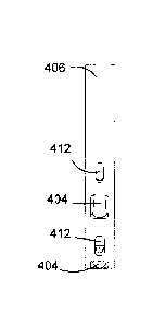
horizontally mounted in the calandria, 100.
[0003] The annular gap between the pressure tubes 106 and calandria tubes 102
are
filled with CO2 gas which acts as an insulator between the "hot" pressure tube
and the
heavy water moderator 112 in the calandria vessel 100. Heavy water 112 flows
through
the pressure tubes, 106, removing heat from the fuel bundles 104 and
transferring it to
steam generators, where secondary circuit light water 116 is heated and
converted into
steam 118 to run a turbine. The balance of the components shown in Figures 1
and 2
(i.e. the control rods 120, heat exchanger 122, light water pump 124, heavy
water pump
- i -
CA 2764270 2018-05-15
126, concrete shielding 128, closure plugs 130, end shield 132, etc.) vary
from one
reactor design to the next.
1_0004], During reactor operation, pressure tube 106 material is subject to
high
pressure (up to 11.3 MPa), high temperature (up to 310 C) and very high gamma
and
neutron radiation fields. The calandria tubes 102 are subjected to head
pressure (from
the heavy water moderator 112 located in the calandria 100). As the inner
pressure tube
106 operates at a relatively high temperature and the outer calandria tube 102
operates at
a much lower temperature, fuel channels in a nuclear reactor, such as a
CANDUTM
reactor, require an annular space to be maintained between the pressure tube
106 and the
coaxial calandria tube 102 in order to maintain the temperature differential,
to allow for
the circulation of gases which thermally insulate the hot pressure tube 106
from the
relatively colder calandria tube 102 and the heavy water moderator 112 which
flows in
the space outside the calandria tube.
[0005] However, the weight of the fuel 104 and coolant inside the pressure
tube 106
would cause it to sag into contact with the calandria tube 102 if it were not
supported at
a few discrete points along its span. Annulus spacers 114 are designed for
transmitting
supporting force and maintaining the required gap between the pairs of
calandria tubes
102 and pressure tubes 106.
[0006] Therefore, annulus spacers 114 are an important component that makes up
a
reactor fuel channel. These spacers 114 maintain the radial spacing between
the two
coaxial tubes (the inner pressure tube 106 and the outer calandria tube 102)
and help the
calandria tubes 102 to support pressure tubes, 106. Typically, four spacers
114 are used
in each fuel channel, each at a different axial position. To provide the
required support
of the pressure tube 106, the annulus spacers 114 must be located at the
proper position.
If a spacer 114 is out of position, the hot pressure tube 106 may come into
contact with
the cooler calandria tube 102, which is unacceptable in the reactor.
- 2 -
CA 2764270 2018-05-15
[0007] Conventionally, garter spring spacers have been used to maintain the
space
between the pressure tube 106 and the calandria tube 102. A garter spring
spacer is
basically a helical spring disposed around the pressure tube 106. Its
convolutions
contact the walls of both the pressure tube 106 and the calandria tube 102.
The spring is
unattached to either tube. A garter spring spacer was disclosed in United
States Patent
No. 3,106,520 issued to Wolfe et al. October 8, 1963.
[0008] Two types of such garter spring spacers have been used in CANDUTM fuel
channels, known as the loose-fit spacer 302 and the snug-fit spacer 304. Their
arrangements are shown in Figure 3. Both garter spring spacers 302, 304
comprise a
closely coiled spring made from a square cross-section wire, assembled on a
circular
girdle wire to form a torus. The design of the garter spring spacers 302, 304
is such that
they are not fixed rigidly in position. Thus, it is possible that a garter
spring spacer 302,
304 may move out of position.
[0009] The loose-fit garter spring spacer 302 does not reliably remain in its
installed
location. The loose-fit garter spring spacer 302 relies on friction to
maintain position.
Some loose-fit garter spring spacers 302 move axially away from their intended
positions during reactor operation thereby causing a major source of concern,
as the
spacers 114 must stay in their intended positions to ensure that the pressure
tube 106 is
adequately supported and remains out of contact with the calandria tube 102.
The
loose-fit garter spring design 302 has been replaced with the snug-fit garter
spring
design 304 for better performance in maintaining its axial position along the
fuel
channel.
[0010] The snug-fit garter spring spacer 304 has been shown to be more
reliable in
maintaining its installed location in the reactor. This is initially done by
spring tension
on the pressure tube 106. Over time the spring tension decreases and the
garter spring
spacer 304 becomes pinched between the pressure tube 106 and calandria tube
102,
which aides in keeping the snug-fit garter spring spacer 304 in position
through friction.
- 3 -
CA 2764270 2018-05-15
The snug-fit garter spring spacer 304 is typically made using Inconel X-750
for the
helical spring coil and Zircaloy-2 for the girdle wire. Inconel X-750 is a
nickel-based
alloy, and it was chosen in part for its ability to maintain the required
spring tension
under the given operating conditions. However, it has been discovered that the
mechanical properties of nickel-based alloys degrade with prolonged exposure
to
radiation, causing concerns about the condition of the Inconel garter springs
over time.
[0011] An additional drawback is that the snug-fit garter spring spacer 304 is
difficult
to detect to confirm its position. Loose-fit garter spring spacers 302 can be
detected
relatively easily using eddy current technology by detecting an induced
current in the
welded girdle wire 306. The snug-fit garter spring spacer 304 cannot be
detected using
the eddy current technique because it does not have a continuous uninterrupted
circuit
around its perimeter, as its girdle wire 308 is not welded; it simply overlaps
itself as it
passes 1.5 times around the pressure tube 106. Techniques based on inspecting
for
pressure tube 106 deformation (sag, ovality, pressure tube-to-calandria tube
gap) have
been used to indirectly identify spacer 114 position. However, techniques
using
pressure tube deformation as a measure of spacer position have the
disadvantage that
they only indicate where a spacer has once resided, but not necessarily where
a spacer is
currently. This is because the pressure tube deformation does not immediately
change
with a change in spacer position. Recently, a vibration-based technique
(termed
MODARTM for MOdal Detection And Repositioning) has been developed to detect
snug-fit garter spring spacer 304 position by monitoring the effect the spacer
load has
on controlled pressure tube vibrations.
[0012] Thus, neither the loose-fit nor snug-fit garter spring spacers 302, 304
are
positively located in the fuel channel. In fact, the garter spring spacers
302, 304 are
designed to roll when relative axial motion occurs between the pressure tube
106 and
calandria tube 102 due to thermal changes and creep, so their position changes
under
operating conditions. This characteristic that the garter spring spacer 302,
304 position
is not fixed results in Nuclear Regulators requiring that reactor operators
perform
- 4 -
CA 2764270 2020-01-16
inspections to verify spacer 114 position. These inspections add cost and
decrease
operating efficiency of the reactor.
[0013] When a change to the spacer axial location occurs, the spacer 114 must
be
repositioned. Repositioning the spacers 114 is difficult and costly, and may
also result
in radiation exposure to those who conduct the procedure.
[0014] Further, because garter spring spacers 302, 304 are not attached to
either the
pressure tube 106 or the calandria tube 102, they must be installed on the
pressure tube
106 after the pressure tube 106 has been placed inside the calandria tube 102.
As a
result, installation of the garter spring spacers 302, 304 is a challenging
procedure
which requires tedious operations to be carried out at the reactor face. The
problem is
exacerbated over the operating time of the fuel channel as increased sag
develops in the
calandria tubes 102. Spacer installation in a sagged fuel channel is
significantly more
challenging than in a straight fuel channel.
[0015] The difficulty in installing the spacers 114 is of particular
significance to the
fuel channel replacement procedures because when a fuel channel is replaced,
the
spacers 114 must be re-installed. Consequently, this adds to the time and cost
of fuel
channel replacement. An improved fuel channel spacer replacement procedure is
desirable not only to reduce the time and expense of the operation but also to
reduce the
radiation dose level to which those who replace the fuel channels may be
exposed.
[0016] It would also be desirable to use only low-neutron cross-section
material, such
as zirconium alloy, in a spacer design, instead of Inconel, to reduce fuel
burn-up and
increase neutron efficiency.
[0017] There is therefore a need for an improved spacer which is positioned
between
the pressure tube and calandria tube. It is also desirable that the improved
spacer
overcomes some of the difficulties inherent in the use of prior art spacers
such as the
garter spring spacer.
- 5 -
CA 2764270 2018-05-15
SUMMARY OF THE INVENTION
[0018] It is an object of the invention to provide an improved spacer design
and in
particular, to provide a spacer design that is fixed in space and cannot be
easily moved
out of position, and that can be easily installed and/or replaced.
[0019] Presently, none of the prior art fuel channel annulus spacers are
'positively'
located in the fuel channel (i.e. there are no physical features that keep the
spacers in
position or prevent them from moving out of position). When spacers move away
from
their intended positions during reactor operation, a major concern arises as
to whether
the pressure tube is adequately supported and remains out of contact with the
calandria
tube.
[0020] According to an aspect of the present invention there is provided a
spacer for
maintaining a pressure tube in spaced relation with a calandria tube in a
nuclear reactor,
wherein an outer profile of the spacer has a close fit with a locally,
circumferentially-expanded profile of the calandria tube. This prevents axial
movement
of the spacer within the calandria tube.
[0021] According to another aspect of the present invention there is provided
a
calandria tube in a nuclear reactor comprising a locally, circumferentially-
expanded
profile for securing a spacer.
[0022] According to a further aspect of the present invention there is
provided a method
of installing a spacer in a nuclear reactor, comprising the steps of:
positioning the spacer
at an end of a calandria tube, the spacer being rotated 90 degrees out of
installed position
about its vertical axis; inserting the spacer into the calandria tube to align
axially with a
formed profile of the calandria tube; rotating the spacer 90 degrees about its
vertical axis
to engage with the formed profile of the calandria tube, and inserting the
pressure tube
through the calandria tube and spacer, fixing the axial position of the
spacer.
- 6 -
CA 2764270 2018-05-15
[0023] Other systems, methods, features and advantages of the invention will
be, or
will become, apparent to one with skill in the art upon examination of the
following
figures and detailed description. It is intended that all such additional
systems, methods,
features and advantages be included within this description, be within the
scope of the
invention, and be protected by the following claims.
BRIEF DESCRIPTION OF THE DRAWINGS
[0024] These and other features of the invention will become more apparent
from the
following description in which reference is made to the appended drawings
wherein:
Figure 1 presents a schematic diagram of a nuclear reactor as known in the
art;
Figure 2 presents a simplified diagram of a calandria and immediately related
components as known in the art;
Figure 3 presents an arrangement of calandria tube, pressure tube and garter
spring
annulus spacers as known in the art;
Figures 4A through 4C present side and front orthogonal, and isometric cutaway
views,
respectively, of the spacer in accordance with an embodiment of the present
invention;
Figures 5A and 5B present the details and dimensions of the spacer body in
accordance
with an embodiment of the present invention;
Figures 6A through 6D present schematic views of the spacer installation
process in an
embodiment of the present invention; and
Figures 7A through 7D present isometric views of the spacer installation
process in an
embodiment of the present invention.
- 7 -
CA 2764270 2018-05-15
DETAILED DESCRIPTION
[0025] One or more currently preferred embodiments have been described by way
of
example. It will be apparent to persons skilled in the art that a number of
variations and
modifications can be made without departing from the scope of the invention as
defined
in the claims.
[0026] As noted above, a problem with the prior art garter spring spacers 302,
304 is
that they are not 'positively' located in the fuel channel, that is, there is
nothing that
physically keeps the prior art garter spring spacers 302, 304 in position or
prevents them
from moving out of position. Further, installation of the prior art garter
spring spacers
302, 304 is a challenging procedure which requires additional operations to be
carried
out at the reactor face. Due to the above-described issues, there has been a
long felt
need in the industry for a new fuel channel spacer to replace the prior art
garter spring
spacers 302, 304. Several concepts have been proposed but heretofore, none
have been
successful. The new fuel channel annulus spacer design provided by the
invention has
been developed to address the performance shortcomings of the prior art garter
spring
type spacers 302, 304.
[0027] The current invention provides a novel spacer design that is positively
located in
space and cannot be easily moved out of position. It can also be easily
installed and/or
replaced. The spacer design also involves a change to the profile of the
calandria tube
102 such that the revised profile is used to help fix the spacer position.
Universal
adoption will replace the prior art garter spring type fuel channel spacers
302, 304.
[0028] In the preferred embodiment of the invention, a novel and elegant
solution to
securing the position of the annulus spacer in the fuel channel is provided by
capturing
the spacer between the pressure tube 106 and a locally expanded section of
ealandria
tube 102. With the system of the invention, fixing the spacer position
requires no
attachments (welds, threaded features, etc.) to either the pressure tube 106
or calandria
tube 102. The locally expanded sections of the calandria tube 102 may be
formed using
- 8 -
CA 2764270 2018-05-15
a known industrial process called hydroforming. This process uses hydraulic
pressure
to apply force to shape the calandria tube 102. In this case, a shaped die
with the desired
form is fit around the outside of the straight calandria tube 102 at the
desired location
and orientation. The die is split to allow it to be removed after
hydroforming, and has a
collar installed around it to hold it securely together during the expansion
process. A
type of plug is installed inside the calandria tube 102, coincident with the
location of the
die on the outside. At each end of the plug a seal is formed against the
inside surface of
the calandria tube 102. The plug includes appropriate ports to allow hydraulic
fluid to
be introduced into the sealed annulus between the plug and calandria tube 102.
The
fluid is then pressurized, which exerts enough force to cause the calandria
tube 102 to
expand outward against the formed die. The calandria tube 102 is left
permanently
deformed by this process. The jigs required would be specially made to fit the
calandria
tube 102 and to produce the desired shape. Generally it is not necessary to
hydroform
old calandria tubes; new calandria tubes are invariably used when building a
new
reactor or refurbishing an old reactor.
[0029] Note that with the expansion of the calandria tubes 102 to accommodate
the new
spacer design, the holes through the calandria vessel 100 generally do not
have to be
made larger. This is because the profile of the expanded section of calandria
tube is
designed such that it is within the envelope of the larger diameter belled
ends that
typically exist on the calandria tubes 102 (see 510 in Figure 5A). Thus, no
modification
to the calandria vessel 100 or the connection between the calandria and
calandria tubes
102 is generally required by the new spacer design.
[0030] The preferred embodiment of the spacer design is shown in Figures 4A
through
4C. The spacer 400 consists of a body 406 in the form of a generally
cylindrical - or
ring-shaped band, which is flattened on the two vertical sides (i.e. left side
408 and right
side 410). The lower portion of the spacer body 406 provides support for a set
of rollers,
404. The rollers 404 are secured to the body 406 using pins 402. In use, the
spacer 400
is positioned inside the calandria tube 102 and the pressure tube 106 rests on
the rollers
- 9 -
CA 2764270 2018-05-15
404. A roller-type support helps to minimize friction and possible wear when
relative
axial motion occurs between the pressure tube 106 and calandria tuber 102. It
also helps
prevent displacement of the spacer 400 when a pressure tube 106 is being
inserted into a
calandria tube 102. The slots 412 in the spacer body 406 allow access to
insert the pins
402 through the rollers 404.
[0031] The outer profile of the spacer body 406 is specifically designed to
facilitate it
being securely positioned inside the calandria tube 102 at locations where a
special
profile has been formed. The profile of the spacer body 406 is shown in the
section
view of Figure 5A. The outside dimension of the spacer 400 at the vertical and
horizontal centerlines 502, 504 of its body approximately matches that of the
inside
diameter of the calandria tube 506. On the flattened vertical sides 408, 410
of the spacer
400, the width is maintained for a small distance above and below the
horizontal
centerline 504, producing the two flat portions shown in the section view. The
curved
portions 508 between the vertical centerline 502 and the flattened portions
408, 410 are
sized to have a radius larger than the inside diameter of the calandria 506,
and slightly
smaller than the inside diameter of the locally expanded portion of the
calandria tube
102 (see 602 in Figure 6A). In the embodiment described herein, the outside
radius for
this curved portion 508 is slightly larger than the standard nominal inside
radius of a
CANDU calandria tube of 2.54 inches. Thus, when the spacer 400 is in its final
position
within the expanded section 602, it will not be possible to displace the
spacer 400
axially because of interference with the unexpanded calandria tube (see 604 in
Figure
6A). The width of the flattened portions 408, 410 is determined simply by the
amount
desired to extend the outside spacer profile beyond the calandria tube body
inside
diameter 506 so as to secure it in place.
[0032] The actual three dimensional profile along the vertical side portion
408, 410 of
the spacer 400 is cylindrical, with the cylindrical axis coinciding with the
spacer centre.
This rounded cross-section of the flattened portions 512, 514 is shown in the
cross-sectional view of Figure 5B. Having the side flattened portions 408, 410
-10-
CA 2764270 2018-05-15
rounded, allows the spacer 400 to be rotated about its vertical axis 502 once
the spacer
400 is in the locally expanded portion of the calandria tube 602, the
curvature of the side
flattened portions 408, 410 matching that of the expanded portion of the
calandria tube
602. This profile also prevents the spacer 400 from rotating about either the
axis of the
calandria tube 102 or about a horizontal axis perpendicular to the calandria
tube axis.
[0033] Figures 6 and 7 illustrate the installation process, Figures 6A through
60
presenting a schematic cross-sectional view from above, and Figures 7A through
70
presenting isometric views.
[0034] To install the spacer 400, it is initially held vertically but rotated
90 degrees
about the vertical axis from its installed position, at the end of the
calandria tube 102, as
shown in Figures 6A and 7A. The spacer 400 is then inserted into the calandria
tube
102 until it is aligned axially with the formed profile of the calandria tube
(i.e. the
expanded portion of the calandria tube 602) as shown in Figures 6B and 7B.
[0035] The spacer 400 is then rotated 90 degrees about the vertical axis to
engage it
with the formed calandria tube 602 matching profile as shown in Figures 6C and
7C.
The flattened sides of the spacer 408, 410 are rounded so that their curvature
matches
the curvature of the expansion in the calandria tube 602, facilitating the
easy rotation of
the spacer 400 into its final position. The pressure tube 106 can then be
installed in the
calandria tube 102 and through the spacer 400. The presence of the installed
pressure
tube 106 prevents the spacer 400 from rotating about its vertical axis. With
the pressure
tube 106 installed, the spacer 400 is fully captured in place.
[0036] A significant feature of the invention is that the calandria tube 102
is locally
formed (expanded) to allow the spacer 400 to be fixed in position. The formed
calandria tube makes many alternate means of designing and fixing a spacer
possible.
For example, the spacer 400 could be hinged to expand into the formed shape
and then
be pinned in the opened configuration to fix it in place. The preferred
embodiment
-11-
CA 2764270 2018-05-15
detailed above is provided for its simplicity of installation. However, other
design
variations based on the same approach of expanded forming of the calandria
tube are
also included in the scope of the invention.
[0037] The new spacer design has many advantages over the conventional
designs. For
example, it secures the spacer 400 in position by capturing it between the
pressure tube
106 and calandria tube 102, therefore it physically keeps the spacer in
position and
prevents it from moving out of position. Further, the spacer 400 can be easily
installed
into position inside of the calandria tube, 102. There are no special
attachment features
that would need to be inspected or remotely manipulated. The spacer 400 can
easily be
removed and re-installed if needed for any practical reason.
[0038] A further advantage of the design of the spacer of the invention is
that it is
mechanically robust and does not require materials of construction to be
chosen based
on resistance to tension or any other requirement originating from the spacer
design
itself. The spacer 400 can therefore be made of zirconium alloys. This will
reduce fuel
burn-up and increase neutron efficiency for the reactor. Suitable oxide
coating on the
pins 402 and rollers 404 may be used to improve the wear characteristics of
the design
and reduce friction.
[0039] There is a huge economic advantage to producing an improved fuel
channel
annulus spacer as described in the present invention. The prior art garter
spring spacers
304, 306 do not have a fixed position. This has caused concerns from Nuclear
Regulators and has resulted in very large expenditures related to inspections
and
assessment of the effects of variations in spacer positions. The issues with
the existing
spacer design are widely known and are important considerations for potential
buyers of
nuclear reactors.
[0040] Implementation of the fuel channel annulus spacer design of the
invention will
improve the operating performance of reactors such as CANDUTM reactors and may
-12-
CA 2764270 2018-05-15
reduce the need for costly inspections. Of course, the new design may be
applied to new
build nuclear reactors and for refurbishment projects (i.e. reactor re-
tubing).
OPTIONS AND ALTERNATIVES
[0041] Many variations to the described spacer are possible. Examples of
variations
include an alternate number of rollers (2 or 5 instead of 4), adding rollers
404 to the top
portion of the spacer 400 in addition to the bottom, use of a solid bearing
instead of a
roller, altering the spacer installation axis away from vertical, changing the
materials of
construction, or using a hinge or latch feature to extend part of the spacer
into the
expanded calandria tube as a means to secure it in place.
CONCLUSIONS
[0042] One or more currently preferred embodiments have been described by way
of
example. It will be apparent to persons skilled in the art that a number of
variations and
modifications can be made without departing from the scope of the invention as
defined
in the claims.
-13-
CA 2764270 2018-05-15