Language selection

Search

Patent 2764275 Summary

Third-party information liability

Some of the information on this Web page has been provided by external sources. The Government of Canada is not responsible for the accuracy, reliability or currency of the information supplied by external sources. Users wishing to rely upon this information should consult directly with the source of the information. Content provided by external sources is not subject to official languages, privacy and accessibility requirements.

Claims and Abstract availability

Any discrepancies in the text and image of the Claims and Abstract are due to differing posting times. Text of the Claims and Abstract are posted:

  • At the time the application is open to public inspection;
  • At the time of issue of the patent (grant).
(12) Patent Application: (11) CA 2764275
(54) English Title: UPPER BODY EXERCISE EQUIPMENT
(54) French Title: APPAREIL D'EXERCICES POUR LE HAUT DU CORPS
Status: Deemed Abandoned and Beyond the Period of Reinstatement - Pending Response to Notice of Disregarded Communication
Bibliographic Data
Abstracts

English Abstract


This invention is an exercise equipment. It is used to exercise the upper
body, mainly
Chest, Arm and Shoulder muscles. With this equipment a different approach is
used to
exercise these muscle groups than with a conventional Bench Press (Bar-Bell)
for the
same muscle groups. This invention has the motions similar to a conventional
Bench-press.
But the weight is not on top/overhead of the Person but located on the Floor
on
either the sides or behind the bench connected through a cable or cables via a
Pulley
system with Handles attached to the other end of the cable.
One lies on the Bench, less than shoulders wide and pushes with the Hands the
two
Handles (one in either hand) up, until the elbows are locked, preferable in a
straight line
and then let back down slowly. The resistance is from the bottom somewhere
below the
shoulders where the first or last Pulley (depends how one traces the system),
in the Pulley
system, is located.
The weight is adjustable by a locking pin, which is inserted into the Holes of
the selected
weight.


Claims

Note: Claims are shown in the official language in which they were submitted.

CLAIMS
The embodiments of the invention in which an exclusive property or privilege
is claimed
are defined as follows:
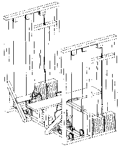
In Claim 1, I claim the "design" itself as seen in FIG.1 and FIG. 2, where all
the elements
(structure, pulley system, stacked weights, etc.) are arranged in a fashion so
that it
simulates the motion or movement of a conventional/generic Bench Press (Bar
Bell) with
all of its benefits plus additional benefits and none of its disadvantages
(benefits are as
follows and are also listed in the specification).
Benefits of Invention:
- Effective "straight up" motion (as with conventional/generic bench
press).
- Acts as a "free weight" (as with conventional/generic bench press).
("Free weights" are more effective)
- No "transfer" of weights to & from weight stand (shelf) necessary.
- Weights can not drop onto the user's chest, face or neck during exercise.
- (Weights are not overhead as with conventional bar bell bench press).
- Because of the previous point there is no need for a second person
(spotter) to assist.
- The actual hand motion could be straight up or towards a point above
ones chest
(For different effects).
In Claim 2, I claim a "rotary handle" shown in (FIG. 9), where one can rotate
the
gripping part (# 14) of the "Rotary Handle" from a "parallel" to a
"perpendicular" hand
position (90 degree or less) in order for different muscle groups to be
exercised
(targeted).
6

In Claim 3, I claim a "curved part" (# 6) of the Bench at or near the waist,
which gives
lateral support for a more enjoyable and more effective workout.
This "curved part" can be a solid part of the bench or an adjustable
attachment but
flexible enough for different size body waist.
The material can be anything flexible yet stiff enough for support and shall
be covert with
cushioning (i.e. Foam and leather).
In Claim 4, I claim the alternative to the "two" cables coming from "two"
pulleys
attached to the Handle (# 7), which would be just "one" cable coming from
"one" pulley
and attached to the Handle (# 7) or the "Rotary Handle" (FIG. 9). The cable
would have
some soft patting/cushioning (i.e. Foam covert with leather) around it where
it makes
contact with the forearm during exercise (not illustrated).
In Claim 5, I claim the alternative of having a "central" "stacked weights"
system
"behind" the bench (or at any other convenient location), which is connected
to the
Handles via four cables (two for each Handle) or just "two" cables as in
"claim 4".
In Claim 6, I claim that the last "Pulleys" before the "Handles" are
adjustable in a way so
that the "width" between the Pulleys on the left side and the Pulleys on the
right side (of
the bench) can be adjusted to approximately the width of the individuals
shoulders (the
person using the equipment) in order to keep the "straight up" motion.
7

Description

Note: Descriptions are shown in the official language in which they were submitted.


CA 02764275 2012-01-16
SPECIFICATION
TITLE
Exercise Equipment
= This invention is an "exercise equipment" for workout of the upper body
muscles.
= Commonly one uses a generic or conventional "bench press" with weights
loaded on
either side of a steel bar (called Bar-Bell), to exercise the upper body
muscles. This type
of exercise equipment has some limitations for once because of the one only
Hand
position (parallel to the chest muscles), which allows one to exercise a fewer
muscle
groups.
Disc type weights are attached to or loaded on both ends of a steel bar (Bar
Bell). The
Bar Bell/weight is overhead as one lifts it out of its resting fixture or
holder, while lying
on a bench. This is an inherent danger, in that, that the weight could drop
onto the
person chest, Neck or Face, if suddenly too heavy or the person having cramps
or any
other types of physical problems.
For this reason a second person (called a spotter) is sometimes asked to stand
behind the
equipment to assist the lifter when assistance is necessary (in the case the
weight gets to
heavy, cramps, etc.) and can not be lifted anymore.
Also with this conventional bench press type, weights have to be carried to
and from the
"weight stand" or "shelf' for different selections of weights.
There are equipments that have a pulley system with handles at the end where
you would
sit upright on a "chair" type, the handles are located on the side and much
farther apart
and therefore have to be pulled forward (horizontally), which does not
simulate the
otherwise effective "Bar-Bell bench press" motion (which is straight up).
1

CA 02764275 2012-01-16
= To overcome these disadvantages this invention is using a pulley system,
with cables,
which has "Handles" attached to one end and "stacked weights" attached to the
other.
By having all the "weights" located at the base of the Equipments, there is no
need to
transport them to and from a "weight stand" or "shelf".
The danger of the weights (Bar Bell) being dropped onto ones Chest, Face or
Neck, is
eliminated by the use of a Pulley system, where the weights are on the side
(or behind by
design) and not overhead.
Therefore there is no need for a "second Person" (Spotter) to stand behind the
"Equipment" in the case the weight gets too heavy or for any other kind of
problems.
By using Handles that one can rotate into a different Hand position enables
one to
exercise additional /different muscle groups than with a "one hand position"
on the Bar of
a conventional bench press.
This Invention has all the benefits of a conventional Bench Press including
the benefit of
the free weights, which is more beneficial to the building of additional
muscles (i.e.
biceps and forearms used as stabilizers) compare to some rigid machines with
levers,
which allows only for a rigid linear motion.
The width between one's hands while doing the exercise is also significant and
can be
adjusted during the exercise.
2

CA 02764275 2012-01-16
DESCRIPTION
= In the Drawings one can recognize the embodiment of the invention, where
FIG.1 is
showing the exercise equipment as a whole in a solid 3D view. FIG. 2 also
shows the
whole equipment in an "open view" also in 3D. In FIG. 3 it shows one side of
the
equipment for a better, detailed view, also in 3D. FIG. 4 shows one side of
the equipment
in solid 3D. FIG. 5 shows a "side" view of one side of the equipment. FIG. 6
shows a
"front" view of the whole equipment. In FIG. 7 it shows a "top" view of the
whole
equipment in solid. FIG. 8 shows a "disassembled" view of one side of the
equipment.
FIG. 9 shows the "Rotary Handle" in 4:1 scale for a better, detailed view.
= The Equipment illustrated in the Drawings is comprised of the "Main
Structure" (# 1),
"Rails" (# 2) to guide the weights as they move up and down, "Stacked Weights"
(# 3), a
"Pulley system" (# 4) (single Pulleys, double Pulley, rotary Pulleys &
cables), a "Bench"
(# 5) with a "curved support Part" (# 6), a "Handle" (# 7), a "resting
Fixture" (# 8) (for
the Handle), "Hooks" (# 9), a "Pull Rod" (# 10), a "lock Pin" (# 11) and
"Cable
Retainers" (# 12), "length adjustment loops" (# 13). Alternatively also the
"Rotary
Handle" (FIG. 9) with the "rotary Gripper" (# 14).
This arrangement is set up on both sides of the bench (one for each Hand) as
illustrated in
FIG.1 and FIG. 2.
= To utilize this equipment first one selects the weight by inserting the
lock pin (# 11)
into the hole of the selected weight (incl. the "pull rod" (# 10), which
attaches the cable
to the "stacked weights" (# 3)).
Then the actual exercise is done by one lying down on the bench (# 5) so that
the Chest is
aligned (same level) approximately with the Handles (# 7) and with the feet
flat on the
floor.
Then one takes both of the Handles (# 7) into the Hands, brings them into
starting
position (close to shoulder) and pushes them straight up in a slow and
consistent motion
until the arms are fully extended or the elbows are gently locked and then
lowers the
3

CA 02764275 2012-01-16
weight slowly to the level of the chest (or starting position), without having
the stacked
weights touching the floor. (This is repeated as required).
The last pulleys before the Handles are sideways rotatable (#15) to allow for
the user to
be in a slightly off position on the bench (not exactly having the shoulders
aligned with
the Handles).
O Once the exercise is completed with the Handles again in the "lower" or
"starting"
position, they then can be placed on the ground or returned into its "resting
fixture" (# 8),
depending on the design (at this point the "stacked weights" are rested on the
floor).
= With the "Rotary Handle" option (FIG. 9), the gripping part (# 14) of the
Handle can
be rotated (90 degrees or less) into a different position (roughly parallel or
perpendicular
to the Chest) so that different muscle groups are being targeted.
Alternative Designs (to the one illustrated and described):
= "Two pulley system" leading to the Handle, as in the illustrated version
but with one
Pulley & cable on either side of the "stacked weights" system (leading to the
same
Handle).
= One central "stacked weights" system behind the bench (or any other
convenient
location) connected to the Pulley system on both side of the bench.
4

CA 02764275 2012-01-16
LIST OF FIGURES & NUMBERS IN DRAWINGS
FIG. 1 - Whole Equipment in solid 3D.
FIG. 2 - Whole Equipment in 3D.
FIG. 3 - One side of Equipment in 3D.
FIG. 4 - One side of Equipment & Rotary Handle solid in 3D.
FIG. 5 - Side view of one side of Equipment.
FIG. 6 - Front view of whole Equipment in solid.
FIG. 7 - Top view of whole Equipment in solid.
FIG. 8 - Disassembled view of one side of Equipment.
FIG. 9 - Rotary Handle.
# 1 - Main Structure
#2 -Rails
# 3 - Stacked weights
# 4 - Pulley system
#5 -Bench
# 6 - Curved Support
# 7 - Handle
# 8 - Resting Fixture
# 9 - Hooks
#1O - Pull Rod
#11 - Lock Pin
# 12 - Cable Retainer
# 13 - Length Adjustment Loops
# 14 - Rotary Gripper
# 15 - Rotatable Pulley

Representative Drawing
A single figure which represents the drawing illustrating the invention.
Administrative Status

2024-08-01:As part of the Next Generation Patents (NGP) transition, the Canadian Patents Database (CPD) now contains a more detailed Event History, which replicates the Event Log of our new back-office solution.

Please note that "Inactive:" events refers to events no longer in use in our new back-office solution.

For a clearer understanding of the status of the application/patent presented on this page, the site Disclaimer , as well as the definitions for Patent , Event History , Maintenance Fee  and Payment History  should be consulted.

Event History

Description Date
Application Not Reinstated by Deadline 2016-01-18
Time Limit for Reversal Expired 2016-01-18
Inactive: Abandoned - No reply to s.30(2) Rules requisition 2015-02-16
Deemed Abandoned - Failure to Respond to Maintenance Fee Notice 2015-01-16
Inactive: S.30(2) Rules - Examiner requisition 2014-08-14
Inactive: Report - QC passed 2014-08-12
Amendment Received - Voluntary Amendment 2014-06-09
Inactive: S.30(2) Rules - Examiner requisition 2014-01-16
Inactive: Report - No QC 2014-01-14
Amendment Received - Voluntary Amendment 2013-10-02
Maintenance Request Received 2013-09-10
Application Published (Open to Public Inspection) 2013-07-16
Inactive: Cover page published 2013-07-15
Inactive: S.30(2) Rules - Examiner requisition 2013-04-10
Inactive: IPC assigned 2012-02-02
Inactive: First IPC assigned 2012-02-02
Inactive: IPC assigned 2012-02-02
Inactive: Filing certificate - RFE (English) 2012-01-30
Inactive: Office letter 2012-01-30
Letter Sent 2012-01-30
Application Received - Regular National 2012-01-30
All Requirements for Examination Determined Compliant 2012-01-16
Request for Examination Requirements Determined Compliant 2012-01-16
Small Entity Declaration Determined Compliant 2012-01-16

Abandonment History

Abandonment Date Reason Reinstatement Date
2015-01-16

Maintenance Fee

The last payment was received on 2013-09-10

Note : If the full payment has not been received on or before the date indicated, a further fee may be required which may be one of the following

  • the reinstatement fee;
  • the late payment fee; or
  • additional fee to reverse deemed expiry.

Patent fees are adjusted on the 1st of January every year. The amounts above are the current amounts if received by December 31 of the current year.
Please refer to the CIPO Patent Fees web page to see all current fee amounts.

Fee History

Fee Type Anniversary Year Due Date Paid Date
Request for examination - small 2012-01-16
Application fee - small 2012-01-16
MF (application, 2nd anniv.) - small 02 2014-01-16 2013-09-10
Owners on Record

Note: Records showing the ownership history in alphabetical order.

Current Owners on Record
HELMUT FARMER
Past Owners on Record
None
Past Owners that do not appear in the "Owners on Record" listing will appear in other documentation within the application.
Documents

To view selected files, please enter reCAPTCHA code :


To view images, click a link in the Document Description column. To download the documents, select one or more checkboxes in the first column and then click the "Download Selected in PDF format (Zip Archive)" or the "Download Selected as Single PDF" button.

List of published and non-published patent-specific documents on the CPD .

If you have any difficulty accessing content, you can call the Client Service Centre at 1-866-997-1936 or send them an e-mail at CIPO Client Service Centre.


Document
Description 
Date
(yyyy-mm-dd) 
Number of pages   Size of Image (KB) 
Description 2012-01-15 5 164
Abstract 2012-01-15 1 26
Claims 2012-01-15 2 67
Representative drawing 2012-03-20 1 18
Abstract 2013-10-01 1 21
Claims 2013-10-01 5 170
Description 2013-10-01 7 255
Description 2014-06-08 7 324
Claims 2014-06-08 3 108
Abstract 2014-06-08 1 23
Drawings 2014-06-08 7 176
Acknowledgement of Request for Examination 2012-01-29 1 189
Filing Certificate (English) 2012-01-29 1 167
Notice: Maintenance Fee Reminder 2014-10-19 1 120
Courtesy - Abandonment Letter (Maintenance Fee) 2015-03-12 1 173
Courtesy - Abandonment Letter (R30(2)) 2015-04-12 1 164
Second Notice: Maintenance Fee Reminder 2015-07-19 1 125
Notice: Maintenance Fee Reminder 2015-10-18 1 118
Correspondence 2012-01-29 1 16
Fees 2013-09-09 3 45