Note: Descriptions are shown in the official language in which they were submitted.
CA 02764486 2016-03-22
86650-1
Wave Energy Electrical Power Generation
TECHNICAL FIELD
This disclosure related to wave-energy conversion devices, and more
particularly to
devices for conversion of wave energy to generation of electrical power.
BACKGROUND
Devices for generation of electrical power by conversion of wave energy are
known, e.g.,
from Wells U.S. 4,383,414; from Houser et al. U.S. 5,411,377; from Fredriksson
et al. U.S.
6,140,712; and from Hirsch U.S. 7,199,481.
SUMMARY
According to one aspect of the disclosure, a wave energy electric power
generation system
comprises: a buoyant body responsive to vertical wave movement and an
associated, relatively
vertically stationary body; a working compressor comprising a compressor
cylinder and a
compressor piston, the compressor piston being mounted for reciprocal movement
relative to the
compressor cylinder to alternately compress air in opposed air compressor
chambers; a pressure
regulator comprising a pressure regulator tank defining a regulator chamber in
communication
with the compressor cylinder for alternately receiving compressed air from
each of the opposed
air compression chambers, a floating pressure regulator piston disposed within
the pressure
regulator tank and mounted to apply pressure to compressed air received into
the regulator
chamber, and a pressure controller coupled to the floating pressure regulator
piston for
controlling pressure applied by the floating pressure regulator piston to
compressed air in the
regulator chamber and an hydraulic dampening system coupled to the floating
pressure regulator
piston for restricting unwanted vertical oscillations of the floating pressure
regulator piston, for
output of a continuous flow of compressed air at relatively constant pressure;
and an air turbine
and generator set disposed in communication with the pressure regulator for
receiving the output
of the flow of compressed air from the pressure regulator at relatively
constant pressure to rotate
the air turbine to drive the generator for generation of electric power.
1
CA 02764486 2016-03-22
86650-1
Implementations of this aspect of the disclosure may include one or more of
the following
features. The compressor further comprises a pair of rolling diaphragms
extending between the
compressor piston and an opposed wall of the compressor cylinder to permit
efficient, almost
frictionless reciprocal movement of the compressor piston relative to the
compressor cylinder to
alternately compress air in the opposed air compression chambers. The pressure
regulator
further comprises a pair of rolling diaphragms extending between the floating
pressure regulator
piston and an opposed wall of the pressure regulator tank to permit efficient,
almost frictionless
reciprocal movement of the floating pressure regulator piston relative to the
pressure regulator
tank. The associated, relatively vertically stationary body comprises a
relatively vertically
stationary neutral buoyancy piston, the compressor cylinder is mounted for
vertical movement
with the buoyant body, and the compressor piston is mounted to the relatively
vertically
stationary neutral buoyancy piston. The compressor cylinder is mounted to a
buoyant body for
vertical movement responsive to vertical wave movement upon a surface of
water, and the
compressor piston is mounted to an associated, relatively vertically
stationary neutral buoyancy
piston. The associated, relatively vertically stationary body comprises a land
or shoreline
mounting, the compressor cylinder is disposed upon the land or shoreline
mounting, and the
compressor piston is mounted to the buoyant body responsive to vertical wave
movement of a
surface of a body of water. The buoyant body is disposed upon a volume of
pressurized air
responsive to vertical wave movement of a surface of a body of water.
According to another aspect of the disclosure, a wave energy electric power
generation
system comprises:
a buoyant body responsive to vertical wave movement and an associated,
relatively
vertically stationary body;
a working compressor comprising a compressor cylinder and a compressor piston,
the
compressor piston being mounted for reciprocal movement relative to the
compressor cylinder
to alternately compress air in opposed air compressor chambers;
a pressure regulator comprising
2
CA 02764486 2016-03-22
86650-1
a pressure regulator tank defining a regulator chamber in communication with
the
compressor cylinder for alternately receiving compressed air from each of the
opposed air
compression chambers,
a floating pressure regulator piston disposed within the pressure regulator
tank and
mounted to apply pressure to compressed air received into the regulator
chamber, and
a pressure controller coupled to the floating pressure regulator piston for
controlling
pressure applied by the floating pressure regulator piston to compressed air
in the
regulator chamber and an hydraulic dampening system coupled to the floating
pressure
regulator piston for restricting unwanted vertical oscillations of the
floating pressure
regulator piston, for output of a continuous flow of compressed air at
relatively constant
pressure; and
an air turbine and generator set disposed in communication with the pressure
regulator for
receiving the output of the flow of compressed air from the pressure regulator
at relatively
constant pressure to rotate the air turbine to drive the generator for
generation of electric power;
and
the associated, relatively vertically stationary body comprises a land or
shoreline
mounting, the compressor cylinder is disposed upon the land or shoreline
mounting, and the
compressor piston is mounted to the buoyant body responsive to vertical wave
movement of a
surface of a body of water;
the buoyant body is disposed upon a closed column of pressurized air
responsive to
reciprocating movement of surface of a water, and the system further comprises
an air handler in
communication with the closed column of pressurized air and adapted for
increasing and
reducing the mass of air within the closed column for adjustment of the
baseline position of the
buoyant body with changes in tide.
Implementations of this or other aspects of the disclosure may include one or
more of the
following features. For example, in a land or shoreline placement, the
compression cylinder
comprises upper and lower opposed circular, open-ended cylindrical elements
defining upper
and lower compression chambers, and the compressor piston and a first circular
open-ended
cylindrical element each defines a circular liquid trough containing a sealant
liquid, the circular
3
CA 02764486 2016-03-22
86650-1
liquid trough defined by the piston being sized and arranged to receive a rim
wall of the upper
circular, open-ended cylindrical element in sealing engagement with the
sealant liquid during
alternating compression and suction strokes, and a circular liquid trough
defined by the lower
circular open-ended cylindrical element being sized and arranged to receive a
rim wall of the
piston element in sealing engagement with the sealant liquid during
alternating suction and
compression strokes. A compression stroke of the compressor piston creates
compression or
pressure of about +20 inches (+50.8 cm) W.C. (or Water Column, a non-SI
(International
System of Units) unit for pressure). The associated liquid trough contains a
sealant liquid having
a specific gravity of approximately 1.0 and provides a sealing depth of at
least about 20 inches
(50.8 cm). A suction stroke of the compressor piston creates suction of about -
3 inches (-7.6 cm)
W.C. The associated liquid trough contains a sealant liquid having a specific
gravity of
approximately 1.0 and provides a sealing depth of at least about 3 inches (7.6
cm).
According to still another aspect of the disclosure, a wave energy electric
power
generation system comprises:
a buoyant body responsive to vertical wave movement and an associated,
relatively
vertically stationary body;
a working compressor comprising a compressor cylinder and a compressor piston,
the
compressor piston being mounted for reciprocal movement relative to the
compressor cylinder
to alternately compress air in opposed air compressor chambers;
a pressure regulator comprising
a pressure regulator tank defining a regulator chamber in communication with
the
compressor cylinder for alternately receiving compressed air from each of the
opposed air
compression chambers,
a floating pressure regulator piston disposed within the pressure regulator
tank and
mounted to apply pressure to compressed air received into the regulator
chamber, and
a pressure controller coupled to the floating pressure regulator piston for
controlling
pressure applied by the floating pressure regulator piston to compressed air
in the
regulator chamber and an hydraulic dampening system coupled to the floating
pressure
regulator piston for restricting unwanted vertical oscillations of the
floating pressure
4
CA 02764486 2016-03-22
86650-1
regulator piston, for output of a continuous flow of compressed air at
relatively constant
pressure; and
an air turbine and generator set disposed in communication with the pressure
regulator for
receiving the output of the flow of compressed air from the pressure regulator
at relatively
constant pressure to rotate the air turbine to drive the generator for
generation of electric power;
and
the wave energy electric power generation system further comprises:
a buoyant body in the form of a lift piston disposed for vertical
reciprocating
movement in a piston cylinder,
the piston cylinder comprises upper and lower opposed circular, open-ended
cylindrical elements defining upper and lower piston chambers, and
the upper and lower circular open-ended cylindrical elements together define a
circular liquid trough containing a sealant liquid,
the circular liquid trough defined by the upper and lower circular, open-ended
cylindrical elements being sized and arranged to receive a rim wall of the
lift piston in
sealing engagement with the sealant liquid during reciprocating vertical
movement of the
lift piston.
Implementations of this or other aspects of the disclosure may include one or
more of the
following features. The upper piston chamber is in communication with an
external ambient
atmosphere. The lower piston chamber is in communication with a closed column
of pressurized
air responsive to vertical wave movement. The buoyant body is disposed upon a
closed column
of pressurized air responsive to reciprocating movement of surface of a water,
and the system
further comprises an air handler in communication with the closed column of
pressurized air and
adapted for adjusting the mass of air within the closed column for adjustment
of the baseline
position of the buoyant body with changes in tide. The air handler comprises
an air pump for
increasing the mass of air contained within the closed column of air. The air
handler comprises
an air relief valve for decreasing the mass of air contained within the closed
column of air.
According to another aspect of the disclosure, a wave energy electric power
generation
system comprises:
5
CA 02764486 2016-03-22
86650-1
a buoyant body responsive to vertical wave movement upon a surface of water
and an
associated, relatively vertically stationary neutral buoyancy piston;
a working compressor comprising
a compressor cylinder mounted for vertical movement with the buoyant body,
a compressor piston mounted to the relatively stationary neutral buoyancy
piston,
and
a pair of rolling diaphragms extending between the compressor piston and an
opposed wall of the compressor cylinder to permit efficient, almost
frictionless reciprocal
movement of the compressor piston relative to the compressor cylinder to
alternately
compress air in opposed air compression chambers;
a pressure regulator comprising
a pressure regulator tank defining a regulator chamber in communication with
the
compressor cylinder for alternately receiving compressed air from each of the
opposed air
compression chambers,
a floating pressure regulator piston disposed within the pressure regulator
tank and
mounted to apply pressure to compressed air received into the regulator
chamber,
a pressure controller coupled to the floating pressure regulator piston for
controlling
pressure applied by the floating pressure regulator piston to compressed air
in the
regulator chamber and an hydraulic dampening system coupled to the floating
pressure
regulator piston for restricting unwanted vertical oscillations of the
floating pressure
regulator piston, for output of a continuous flow of compressed air at
relatively constant
pressure, and
a pair of rolling diaphragms extending between the floating pressure regulator
piston
and an opposed wall of the pressure regulator tank to permit efficient, almost
frictionless
reciprocal movement of the floating pressure regulator piston relative to the
pressure
regulator tank; and
an air turbine and generator set disposed in communication with the pressure
regulator for
receiving the output of the flow of compressed air from the pressure regulator
to rotate the air
turbine to drive the generator for generation of electric power.
6
CA 02764486 2016-03-22
86650-1
Implementations of either of the above aspects of the disclosure may include
one or more
of the following features. The pair of rolling diaphragms extending between
the compressor
piston and an opposed wall of the compressor cylinder defines a closed
compressor region, and
the system further comprises a vacuum pump in communication with the closed
compressor
region. The vacuum pump depressurizes the closed compressor region to a
predetermined
pressure. The predetermined pressure is of the order of -6 inches (-15.2 cm)
W.C. The floating
pressure regulator piston is mounted in the regulator tank upon a central rod
having, on at least
one side of the floating pressure regulator piston, a square cross-section
portion engaged in a
corresponding square aperture, for resisting relative rotation between the
floating pressure
regulator piston and the regulator tank. The pair of rolling diaphragms
extending between the
floating pressure regulator piston and an opposed wall of the regulator tank
defines a closed
regulator region, and the system further comprises a vacuum pump in
communication with the
closed regulator region. The vacuum pump depressurizes the closed regulator
region to a
predetermined pressure. The predetermined pressure is of the order of -6
inches (-15.2 cm) W.C.
According to another aspect of the disclosure, a wave energy electric power
generation
system comprises:
a buoyant body responsive to vertical wave movement and an associated,
relatively
vertically stationary body;
a working compressor comprising a compressor cylinder and a compressor piston,
the
compressor piston being mounted for reciprocal movement relative to the
compressor cylinder
to alternately compress air in opposed air compressor chambers;
a pressure regulator comprising
a pressure regulator tank defining a regulator chamber in communication with
the
compressor cylinder for alternately receiving compressed air from each of the
opposed air
compression chambers,
a floating pressure regulator piston disposed within the pressure regulator
tank and
mounted to apply pressure to compressed air received into the regulator
chamber, and
a pressure controller coupled to the floating pressure regulator piston for
controlling
pressure applied by the floating pressure regulator piston to compressed air
in the
6a
CA 02764486 2016-03-22
86650-1
regulator chamber and an hydraulic dampening system coupled to the floating
pressure
regulator piston for restricting unwanted vertical oscillations of the
pressure regulator, for
output of a continuous flow of compressed air at relatively constant pressure;
and
an air turbine and generator set disposed in communication with the pressure
regulator for
receiving the output of the flow of compressed air from the pressure regulator
at relatively
constant pressure to rotate the air turbine to drive the generator for
generation of electric power;
the wave energy generation system further comprises a closed air system
comprising:
a reservoir for receiving, storing and delivering a closed system of air, and
a closed system of conduits for delivery of air among the compressor, the
pressure
regulator, the air turbine, and the reservoir.
Implementations of the above aspect of the disclosure may include one or more
of the
following features. The closed air system reservoir comprises: a flexible
bladder defining a
volume for receiving, storing and delivering the closed system air, and a tank
containing the
bladder and defining an ambient air region external of the bladder. The closed
system of
conduits comprises check valves for controlling air flow to and from the
compressor. The
pressure regulator and the compressor are in communication through a
compressed air conduit.
The compressed air conduit comprises check valves for controlling the
direction of air flow to
between the compressor and the pressure regulator. The wave energy generation
system further
comprises an air pump. The hydraulic dampening system comprises a double
acting piston
coupled with the floating pressure regulator piston and responsive to vertical
velocity of the
floating pressure regulator piston within the pressure regulator chamber for
controlling flow rate
of hydraulic pressure fluid to each side of a double acting piston, for
restricting unwanted
vertical oscillations of the floating pressure regulator piston. The
compressor piston is mounted
in the compressor cylinder upon a central rod having, on one side of the
compressor piston, a
square cross-section portion engaged in a corresponding square aperture, for
resisting relative
rotation between the compressor piston and the compressor cylinder. The
floating pressure
regulator piston is mounted in the regulator tank upon a central rod having,
on at least one side
of the floating pressure regulator piston, a square cross-section portion
engaged in a
corresponding square aperture, for resisting relative rotation between the
floating pressure
6b
CA 02764486 2016-03-22
86650-1
regulator piston and the regulator tank. The wave energy electric power
generation system
further comprises means for transmission of generated electrical power for
consumption at a
remote location. The wave energy generation system further comprises an air
pump. Other
methods to prevent rotation of the piston within the cylinder, such as a
sliding shaft key or a
single flat, may be used in the alternative.
According to another aspect of the disclosure, a wave energy electric power
generation
system comprises:
a buoyant body responsive to vertical wave movement and an associated,
relatively
vertically stationary body;
a working compressor comprising a compressor cylinder and a compressor piston,
the
compressor piston being mounted for reciprocal movement relative to the
compressor cylinder
to alternately compress air in opposed air compressor chambers;
a pressure regulator comprising
a pressure regulator tank defining a regulator chamber in communication with
the
compressor cylinder for alternately receiving compressed air from each of the
opposed air
compression chambers,
a floating pressure regulator piston disposed within the pressure regulator
tank and
mounted to apply pressure to compressed air received into the regulator
chamber, and
a pressure controller coupled to the floating pressure regulator piston for
controlling
pressure applied by the floating pressure regulator piston to compressed air
in the
regulator chamber and an hydraulic dampening system coupled to the floating
pressure
regulator piston for restricting unwanted vertical oscillations of the
floating pressure
regulator piston, for output of a continuous flow of compressed air at
relatively constant
pressure; and
an air turbine and generator set disposed in communication with the pressure
regulator for
receiving the output of the flow of compressed air from the pressure regulator
at relatively
constant pressure to rotate the air turbine to drive the generator for
generation of electric power;
wherein the associated, relatively vertically stationary body comprises a land
or shoreline
mounting, the compressor cylinder is disposed upon the land or shoreline
mounting, and the
6c
CA 02764486 2016-03-22
86650-1
compressor piston is mounted to the buoyant body responsive to vertical wave
movement of a
surface of a body of water, the buoyant body being disposed upon a volume of
pressurized air
responsive to vertical wave movement of a surface of a body of water; and
the wave energy electric power generation system further comprises
a buoyant body in the form of a lift piston disposed for vertical
reciprocating
movement in a piston cylinder,
the piston cylinder comprises upper and lower opposed circular, open-ended
cylindrical elements defining upper and lower piston chambers, and
the upper and lower circular open-ended cylindrical elements together define a
circular liquid trough containing a sealant liquid,
the circular liquid trough defined by the upper and lower circular, open-ended
cylindrical elements being sized and arranged to receive a rim wall of the
lift piston in
sealing engagement with the sealant liquid during reciprocating vertical
movement of the
lift piston.
Implementations of the above aspect of the disclosure may include one or more
of the
following features. The upper piston chamber is in communication with an
external ambient
atmosphere. The lower piston chamber is in communication with a closed column
of pressurized
air responsive to vertical wave movement. The buoyant body is disposed upon a
closed column
of pressurized air responsive to reciprocating movement of surface of a water,
and the system
further comprises an air handler in communication with the closed column of
pressurized air and
adapted for adjusting the mass of air within the closed column for adjustment
of the baseline
position of the buoyant body with changes in tide. The air handler comprises
an air pump for
increasing the mass of air contained within the closed column of air. The air
handler comprises
an air relief valve for decreasing the mass of air contained within the closed
column of air. The
air handler comprises an air relief valve for decreasing the mass of air
contained within the
closed column of air.
According to still another aspect of the disclosure, a wave energy electric
power
generation system comprises:
6d
CA 02764486 2016-03-22
86650-1
a buoyant body responsive to vertical wave movement upon a surface of water
and an
associated, relatively vertically stationary neutral buoyancy piston;
a working compressor comprising
a compressor cylinder mounted for vertical movement with the buoyant body,
a compressor piston mounted to the relatively stationary neutral buoyancy
piston,
and
a pair of rolling diaphragms extending between the compressor piston and an
opposed wall of the compressor cylinder to permit efficient, almost
frictionless reciprocal
movement of the compressor piston relative to the compressor cylinder to
alternately
compress air in opposed air compression chambers;
a pressure regulator comprising
a pressure regulator tank defining a regulator chamber in communication with
the
compressor cylinder for alternately receiving compressed air from each of the
opposed air
compression chambers,
a floating pressure regulator piston disposed within the pressure regulator
tank and
mounted to apply pressure to compressed air received into the regulator
chamber,
a pressure controller coupled to the floating pressure regulator piston for
controlling
pressure applied by the floating pressure regulator piston to compressed air
in the
regulator chamber and an hydraulic dampening system coupled to the floating
pressure
regulator piston for restricting unwanted vertical oscillations of the
floating pressure
regulator piston, for output of a continuous flow of compressed air at
relatively constant
pressure, and
a pair of rolling diaphragms extending between the floating pressure regulator
piston
and an opposed wall of the pressure regulator tank to permit efficient, almost
frictionless
reciprocal movement of the floating pressure regulator piston relative to the
pressure
regulator tank; and
an air turbine and generator set disposed in communication with the pressure
regulator for
receiving the output of the flow of compressed air from the pressure regulator
to rotate the air
turbine to drive the generator for generation of electric power;
6e
CA 02764486 2016-03-22
86650-1
the wave energy generation system further comprising a closed air system
comprising:
a reservoir for receiving, storing and delivering a closed system of air, and
a closed system of conduits for delivery of air among the compressor, the
pressure
regulator, the air turbine, and the reservoir.
Implementations of the above aspect of the disclosure may include one or more
of the
following features. The closed air system reservoir comprises a flexible
bladder defining a
volume for receiving, storing and delivering the closed system air, and a tank
containing the
bladder and defining an ambient air region external of the bladder. The wave
energy generation
system further comprises an air pump. The pressure regulator and the
compressor are in
communication through a compressed air conduit. The compressed air conduit
comprises check
valves for controlling the direction of air flow to between the compressor and
the pressure
regulator. The wave energy generation system further comprises an air pump.
The closed system
of conduits comprises check valves for controlling air flow to and from the
compressor.
The disclosure thus features an improved wave energy electrical power
generation system
suited for operation of single or multiple units on a buoyant body and on
shore. Effective and
efficient sealing, e.g. of a closed air system, may be provided between moving
elements of the
system compressor and/or the system pressure regulator using a pair of rolling
diaphragm seals,
e.g. with the seal region under vacuum, or using liquid sealant in circular
liquid seal troughs.
Compressed air delivered alternately from opposite chambers of the compressor
is delivered into
the pressure regulator, and the pressure regulator, which may include a
pressure controller
and/or an hydraulic dampening system, in turn delivers a continuous flow of
compressed air at
relatively constant pressure to an air turbine for driving an associate
generator. Systems for
accommodating or adjusting to changes in water surface level due to tidal
changes are also
provided.
The details of one or more implementations of the disclosure are set forth in
the accompa-
nying drawings and the description below. Other features, objects, and
advantages of the
disclosure will be apparent from the description and drawings, and from the
claims.
6f
CA 02764486 2016-03-22
86650-1
DESCRIPTION OF DRAWINGS
FIG. 1 is a somewhat diagrammatic representation of a wave energy electrical
power
generation system of the disclosure.
FIG. 2 is a somewhat diagrammatic side plan view of the air compressor of the
power
generation system of FIG. 1, with a piston mounted to a central rod for
vertical movement
relative to a cylinder, and the piston and cylinder sealed together by
depressurized rolling
diaphragms.
FIGS. 3 and 3A are side and top section views, respectively, of the air
compressor of
FIG. 2, showing inter-engagement of a square shaft and square orifice, for
resisting rotational
movement of the piston relative to the compressor cylinder.
FIGS. 4 and 5 are side section views of alternative clamping arrangements for
mounting
an inner rim of an upper rolling diaphragm to the piston, for extending
between the piston and
the cylinder within the volume of the compressor.
FIG. 6 is a similar side section view of a clamping arrangement for mounting
an outer rim
of the upper rolling diaphragm to the cylinder, again, for extending between
the piston and the
cylinder within the volume of the compressor.
=
6g
CA 02764486 2011-12-05
WO 2010/144384
PCT/US2010/037682
FIG. 7 is a side section view of a vacuum inlet through the cylinder wall, for
depressurizing the region between the piston and the cylinder, bounded by the
upper and
lower rolling diaphragms.
FIG. 8 represents a sample calculation of the radius dimensions of the
top/outer
rim and the bottom/inner rim of the rolling diaphragms.
FIGS. 9 and 9A are side and top section views of the pressure regulator of the
power generation system of FIG. 1, showing inter-engagement of a square shaft
and
square orifice, for resisting rotational movement of the floating piston
relative to the
regulator tank. FIG 9B is a side section view of the vacuum inlet through the
tank wall.
FIG. 10 is a somewhat diagrammatic side section representation of a shoreline
installation of another wave energy electrical power generation system of the
disclosure.
FIG. 11 is a somewhat diagrammatic top plan representation of an expandable
arrangement of multiple elements of the shoreline installation of the wave
energy
electrical power generation system of FIG. 10.
FIG. 12 is a somewhat diagrammatic side plan view of an air compressor for
another implementation of a shoreline installation of the wave energy
electrical power
generation system of FIG. 10, equipped with an alternative liquid sealing
arrangement
and a tide adjusting mechanism.
FIG. 12A is an exploded view of the air compressor of FIG. 12, and FIGS. 12B
and 12C, FIGS. 12D and 12E, and FIGS. 12F and 12G are top and bottom plan
views,
respectively, of the compressor top chamber element, the compressor
intermediate piston
element, and the compressor base chamber element of the air compressor of FIG.
12.
FIG. 13 is a somewhat diagrammatic side plan view of an air compressor for yet
another implementation of a shoreline installation of the wave energy
electrical power
generation system of FIG. 10, equipped with an alternative tide adjusting
mechanism in
the form of a float tank.
FIG. 14 is a somewhat diagrammatic side plan view of an air compressor
assembly for another implementation of a shoreline installation of the wave
energy
electrical power generation system of FIG. 10, equipped with an alternative
tide adjusting
mechanism in the form of a neutral buoyancy piston lifted and lowered by air
pressure,
and using the alternative liquid sealing arrangement of FIGS. 12 and 12A.
7
CA 02764486 2011-12-05
WO 2010/144384
PCT/US2010/037682
FIG 14A is a somewhat diagrammatic, sectional side plan view of an air
compressor assembly for the implementation of a shoreline installation of the
wave
energy electrical power generation system of FIG. 14, using another
alternative liquid
sealing arrangement.
FIG. 15 is a somewhat diagrammatic side plan view of another implementation of
the wave energy electrical power generation system shoreline installation of
FIG. 14, and
FIGS. 15A through 15H represent sample calculations for a representative air
compressor
and tide adjusting mechanism assembly of FIG. 15.
FIG. 16 is a side section view of another implementation of an air compressor
of
the power generation system of FIG. 1, with conduits for flow of air into and
out of the
compressor cylinder.
Like reference symbols in the various drawings indicate like elements.
DETAILED DESCRIPTION
Referring to FIG. 1 et seq., a wave energy electrical power generation system
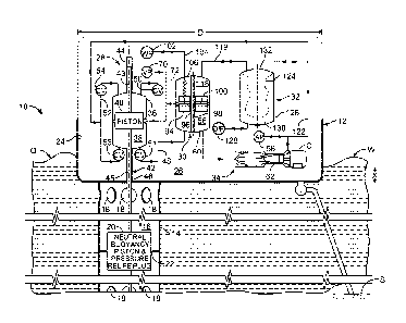
10
of the disclosure has a large floating buoy 12, having a diameter, D, e.g.
about fifteen
feet, anchored to the sea floor, S. A cylindrical wall 14 extends below the
buoy 12 to
define a close-fitting chamber 16. The chamber wall defines a plurality of
open water
flow orifices 18 above and below a neutral buoyancy piston 20, which is
positioned in the
region of a narrow plug orifice 22 in a relatively vertically stationary
position.
An upper body portion 24 of the floating buoy 12 defines a chamber 26, within
which are disposed the components of the system 10 for conversion of wave
energy for
generation of electricity, including an air compressor 28, a pressure
regulator 30, a closed
air reservoir 32, and an impulse air turbine and generator set 34.
Briefly, motion of the ocean surface waves, W, causes the floating buoy 12 to
rise
and fall, while the neutral buoyancy piston 20 remains relatively vertically
stationary. The
air compressor 28 has a closed tank or cylinder 36, which is fixedly mounted
to the
floating buoy 12 within the chamber 26, and also rises and falls with movement
of the
floating buoy in response to motion of the ocean waves. The cylinder 36
defines a
compressor chamber 38, within which is disposed a compressor piston 40. The
compressor piston is mounted to a central rod 42, which is connected at its
lower end to
8
CA 02764486 2011-12-05
WO 2010/144384
PCT/US2010/037682
the neutral buoyancy piston 20 that is maintained relatively vertically
stationary (i.e., as
opposed to the rising and falling wave motion of the floating buoy and the
compressor
cylinder).
Referring also to FIGS. 2, 3, and 3A, the central rod 42, at its upper end 43,
is
received within a closed tube 44 at the top of the cylinder 36, to provide an
air seal. The
rod end 43 and tube 44 may both be square in cross-section, thereby to resist
rotation of
the piston 40 relative to the cylinder 36. The lower end 45 of the central rod
42 extends
through a tube 46 at the bottom of the cylinder 36. This lower tube 46 is
open, but is
provided with water and air sealing. In one implementation, the compressor
piston 40 has
a vertical height, Hp, e.g. of 4 feet, 6 inches (1.37 m), with vertical
clearance, Fic, e.g. of
4 feet (1.22 m), from each of the top and bottom ends of the compressor
cylinder 36
when the system is at rest, e.g. in calm conditions, and the compressor
chamber has a
height, HT, e.g. of 12 feet, 6 inches (3.81 m). Hydraulic shock absorbers (not
shown) may
also be provided to resist unwanted impact of the compressor piston 40 with
the top and
bottom ends of the cylinder 36, e.g. during periods of heavier weather.
Movement of the compressor piston 40 relative to the compressor cylinder
chamber 38, i.e. reciprocal vertical movement of the compressor piston within
the
compressor chamber, alternately compresses the volumes of air contained within
the
upper chamber portion 38A and the lower chamber portion 38B of the chamber 38
of the
compressor cylinder 36, in turn. The volume of air within the chamber portion
under
compression is delivered via compressed air conduit 48, through check valve 50
or 51
(e.g., with +3 inch (+7.6 cm) W.C. cracking pressure) into the lower chamber
56 of the
pressure regulator tank 60. Simultaneously, air from flexible bladder 124 of
the closed air
reservoir 32 and/or spent air pumped by air pump 58 from the impulse air
turbine 62 of
the impulse air turbine and generator set 34 is delivered into the opposed
chamber portion
of the compressor cylinder 36 via air inlet conduit 52 through check valve 53
or 54 (also,
e.g., with +3 inch (+7.6 cm) W.C. cracking pressure).
Referring also to FIGS. 2 and 4-6, upper and lower flexible rolling diaphragms
64, 66, respectively, e.g. 0.035 inch (0.9 mm) thick urethane, are mounted to
extend
between the compressor piston 40 and the wall 37 of the compressor cylinder
36. For
example, referring to FIGS. 4 and 5, in a first implementation, an
inner/bottom rim 78 of
9
CA 02764486 2011-12-05
WO 2010/144384
PCT/US2010/037682
the rolling flexible diaphragm 64 is engaged in a notch 80 defined in the
upper wall
surface of the piston 40, and secured with a clamp ring 82 by bolts 84 (one is
shown). In
another implementation, shown in FIG. 5, the inner/bottom rim 78 of the
rolling flexible
diaphragm 64 is engaged between clamp rings 86, 88 secured by bolts 90 (again,
one is
shown) to the surface of the piston. In FIG. 6, the outer/top rim 79 of the
rolling flexible
diaphragm 64 is engaged between clamp rings 134, 136 secured by bolts 138
(again, one
is shown) in a recess defined by an access plate 140 secured to the wall of
the compressor
cylinder 36. Referring again to FIG. 2, these or other clamp rings or similar
elements 92
of suitable design and operation may be employed to secure the inner/bottom
rims 78 and
the outer/top rims 79 of the upper and lower flexible rolling diaphragms 64,
66 in sealing
engagement with the compressor piston 40 and with the compressor cylinder 36,
respectively. The outer/top rims of the flexible rolling diaphragms may also
be secured to
the compressor cylinder at locations other than as shown, e,g., in FIG. 2.
The rolling flexible diaphragms 64, 66 thus permit efficient, almost
frictionless
reciprocal movement of the piston 40 within the cylinder 36, without loss of
pressure.
The sealed region 68 defined by the flexible diaphragms 64, 66 between the
wall 37 of
the cylinder 36 and the opposed surface of the piston 40, maintained at -6
inches (-15.2
cm) W.C. by vacuum pump 70 acting through conduit 72, and thereafter acting
through
vacuum port 74 (FIG. 7) and vacuum distribution plate 76 (FIG. 3) in the wall
37 of the
compressor cylinder 36, serves to resist collapse of the rolling diaphragm
seal during a
suction stroke. It also maintains seal shape, e.g. when system air pressure
falls to
atmospheric conditions when the sea is calm. Use of the flexible rolling
diaphragms 64,
66 also eliminates the need for machined surfaces held to tight dimensional
tolerances.
For example, the surfaces and tolerances of compressor 28 (and pressure
regulator 30)
may only need to be those typically produced in the manufacture of above
ground storage
tanks of similar size, and vacuum space clearance, C (FIG. 4), e.g. two inches
(5.1 cm),
may be maintained between the opposed surfaces of the compressor cylinder 36
and the
piston 40. A sample calculation of the radius dimension of the inner (or
bottom) rim 78
and the outer (or top) rim 79 of the rolling diaphragm may be seen in FIG. 8.
Referring now to FIGS. 1, 9, and 9A, in the lower chamber 56 of the pressure
regulator tank 60, compressed air from the compressor 28 is maintained under
pressure
CA 02764486 2011-12-05
WO 2010/144384
PCT/US2010/037682
by floating or roof piston 94, which is mounted within the regulator tank 60
on vertical
rod 98. The piston 94 is fixedly mounted to the rod, thus to resist leakage of
compressed
air from the lower chamber through any aperture between the piston 94 and the
rod 98.
The vertical rod is supported to the regulator tank by upper and lower bearing
supports
and slide bearings 96. The level of pressure within the lower chamber of the
regulator
tank is controlled by regulation of the volume, i.e. weight, of water in the
variable
volume water ballast tank 100, which is delivered to, or removed from, the
piston 94 by
the water pump 102, through water conduit 104 and hose 106 (which is shown
coiled to
accommodate vertical movement of the floating piston 94), facilitating output
of a
continuous flow of compressed air at relatively constant pressure.
The floating piston is baffled internally (not shown) to resist sloshing of
water
within the ballast tank 100 as the floating buoy 12 rocks back and forth due
to wave
action. This arrangement assists in ensuring that uneven downward force does
not
adversely affect performance of the sliding bearing supports 96 for the
floating piston 94.
As in the case of the compressor 28, one end of the vertical rod 98, e.g. the
upper end,
and the corresponding receiving aperture 99 defined at the top of the
regulator tank (FIG
9B) may both be square in cross-section, thereby to resist rotation of the
floating piston
94 relative to the regulator tank 60.
An hydraulic dampening system 105 for restricting unwanted vertical
oscillations
of the floating piston 94 and maintaining the output of a continuous flow of
compressed
air at relatively constant pressure includes a double acting piston 107. The
piston is
coupled with the floating piston and responsive to the vertical velocity of
the floating
piston for controlling flow rate of hydraulic pressure fluid to each side of a
double acting
piston 107. This arrangement also facilitates output of a continuous flow of
compressed
air at relatively constant pressure.
Referring to FIGS. 9, 9A, and 9B, as in the case of the air compressor 28,
effective and efficient sealing is maintained between the floating piston 94
and the
opposed wall of the pressure regulator tank 60 by rolling flexible diaphragms
108, 110
that permit efficient, almost frictionless reciprocal movement of the piston
94 within the
regulator tank 60, without loss of pressure. The sealed region 112 defined by
the flexible
diaphragms 108, 110 between the wall of the cylinder 60 and the opposed
surface of the
11
CA 02764486 2011-12-05
WO 2010/144384
PCT/US2010/037682
piston 94, maintained at -6 inches (-15.2 cm) W.C. by vacuum pump 70 acting
through
conduit 72, and thereafter acting through vacuum port 114 (FIG. 9B) and vacuum
distribution plate 116 (FIG. 9) in the wall of the regulator tank 60.
Operation under
vacuum serves to resist collapse of the rolling diaphragm seals during
movement of the
piston, and also maintains seal shape, e.g. when system air pressure falls to
atmospheric
conditions, such as when the sea is calm. As described above, use of the
flexible rolling
diaphragms 108, 110 also eliminates the need for machined surfaces held to
tight
dimensional tolerances, as the surfaces and tolerances may only need to be
those typically
produced in the manufacture of above ground storage tanks of similar size.
The upper chamber 118 of the pressure regulator tank 60 is connected to the
closed air system region 132 with the flexible bladder 124 of closed air
reservoir 32 by
conduit 119. This arrangement allows flow of air into and out of the chamber
118 to
accommodate vertical movement of the floating piston 94 within the regulator
tank 60
while maintaining ambient pressure in the upper chamber of the tank.
While output of compressed air from the compressor 28 goes to zero each time
the compressor piston 40 reverses direction with motion of the waves, the
pressure
regulator 30 delivers a continuous flow of compressed air at constant pressure
from the
lower chamber 56 of the pressure regulator tank 60 to drive rotation of the
air impulse
turbine 62 in the impulse air turbine and generator set 34, to drive the
generator 120 for
generation of electricity to be delivered to a power grid on shore by suitable
undersea
cable (not shown). In a preferred implementation, the impulse air turbine 62
may be
equipped with an inflatable toroid throttle for speed control, and the coupled
generator
120 may have variable load control.
Air pump 58, in communication with conduit 122, extracts spent air from the
flexible bladder 124 or delivers ambient air to the bladder of the closed
system air
reservoir 32 to maintain the desired system pressure. The total volume of air
in the
enclosed system remains relatively constant; however, the total mass of air
will typically
vary depending on the operating pressure selected to drive the impulse
turbine. It is
expected that operating pressure will vary between +6 inches (+15.2 cm) W.C.
and +20
inches (+50.8 cm) W.C. Where the system starts up and a pressure of +6 inches
(+15.2
cm) W.C. is selected and controlled by the pressure regulator 30, outside air
must be
12
CA 02764486 2011-12-05
WO 2010/144384
PCT/US2010/037682
added to the system to make up for the volume of air compressed to the +6
inches (+15.2
cm) W.C. level. For every 100 cubic feet (2.83 cubic meters) of air at +6
inches (+15.2
cm) W.C., the air pump 58 must inflow 1.5 cubic feet (4.2 x 10⁻² cubic meters)
of air at
atmospheric pressure to maintain atmospheric pressure on the discharge side of
the
impulse turbine 62. Each additional +4 inches (+10.2 cm) W.C. increase
selected would
require 1.0 cubic foot (2.8 x 10⁻² cubic meters) of air pumped into the
system.
Conversely, the system must draw air out of the system to maintain internal
pressure
equal to atmospheric pressure when the barometric pressure falls. Rising
barometric
pressure will signal the need to pump in additional air to maintain the
desired 1 inch
(2.5 cm) W.C. differential to atmospheric pressure. The flexible bladder 124
provides an
inflatable reservoir for temporary storage of air volume for use in the closed
air system.
In this manner, a closed volume of air, e.g. air that has been treated, e.g.
dried or
lubricated, can be conserved and used through repeated cycles. In contrast,
air in the
ambient air region 130 of the air reservoir tank 126 external of the bladder
124, flowing
in and out through the ambient air orifice and filter 128 in response to
changes in volume
of the closed air system region 132 of the flexible bladder 124, may be drawn
from the
atmosphere and used without pretreatment.
Referring again to FIGS. 1 et seq., a wave energy electrical power generation
system 10 of the disclosure, as described above, may be mounted in a large
floating buoy
12 anchored to the sea floor. A cylindrical wall 14 extends below the buoy to
define a
close-fitting chamber 16.
The floating buoy chamber 24 rests on the ocean surface, 0, preferably with a
displacement, X, e.g. of approximately 6 inches (15.2 cm), to provide force
for
compressing air in the compressor 28 to +28 inches (+71.1 cm) W.C. Motion of
the ocean
surface waves, W, causes the floating buoy 12 to rise and fall. The air
compressor
cylinder 36, mounted to the floating buoy within the chamber 26, also rises
and falls with
movement of the floating buoy in response to motion of the ocean waves, while
the
compressor piston 40 within the compressor cylinder chamber 38, and mounted to
a
central rod 42 connected to the neutral buoyancy piston 20, is maintained
relatively
vertically stationary.
13
CA 02764486 2011-12-05
WO 2010/144384
PCT/US2010/037682
The movement of the compressor cylinder chamber 38 relative to the compressor
piston 40, i.e. reciprocal vertical movement of the compressor piston within
the
compressor chamber, alternately compresses the volumes of air contained within
the
upper chamber 38A and lower chamber 38B of the compressor cylinder, in turn.
The
volume of air within the chamber under compression is delivered via compressed
air
conduit 48, through check valve 50 or 51, into the lower chamber of the
pressure
regulator tank 60. Simultaneously, air from the closed air reservoir 132
within flexible
bladder 124 and the continuous air flow discharged from the impulse air
turbine 62 are
delivered into the opposed chamber of the compressor cylinder via conduit 52
through
check valve 53 or 54. Flexible rolling diaphragms 64, 66 mounted between the
compressor piston 40 and the wall of the compressor cylinder 36, defining a
closed
region 68 maintained at -6 inches (-15.2 cm) W.C., permit efficient, almost
frictionless
reciprocal movement of the piston within the cylinder, without loss of
pressure.
Maintaining the regions defined by the flexible diaphragms 64, 66 between the
wall of
the compressor cylinder or tank 36 and the opposed surface of the piston 40
under
vacuum serves to resist collapse of the seal during a suction stroke, and also
maintains
seal shape, e.g. when system air pressure falls to atmospheric conditions,
such as when
the sea is calm. Use of the flexible rolling diaphragms also eliminates the
need for
machined surfaces held to tight dimensional tolerances. For example, the
surfaces and
tolerances may only need to be those typically produced in the manufacture of
above
ground storage tanks of similar size.
In the pressure regulator tank 60, compressed air from the compressor 28 is
maintained under pressure in the lower chamber portion 56 by floating or roof
piston 94,
which is mounted within the regulator tank 60 by sliding bearing supports 96
on vertical
rod 98. The level of pressure within the lower chamber portion 56 of the
regulator tank 60
is controlled by regulation of the volume, i.e. weight, of water ballast,
which is delivered
to or removed from the variable volume water ballast tank 100 in piston 94 by
operation
of the water pump 102 through conduit 104 and hose 106, which is coiled to
accommodate vertical movement of the floating piston 94. The floating piston
94 is
baffled internally to resist sloshing of water within the ballast tank as the
floating buoy
rocks back and forth due to wave action. This arrangement assists in ensuring
that uneven
14
CA 02764486 2011-12-05
WO 2010/144384
PCT/US2010/037682
downward force does not adversely affect the sliding bearing supports 96 for
the floating
piston. As in the compressor, effective and efficient sealing is maintained
between the
floating piston 94 and the wall of the tank 60 by flexible rolling diaphragms
108, 110,
with the region 112 between the flexible rolling diaphragms mounted between
the
floating piston 94 and the wall of the pressure regulator tank 60 maintained
at -6 inches (-
15.2 cm) W.C. by vacuum pump 70 acting through conduit 72, vacuum port 74, and
vacuum distribution plate 76. This vacuum condition permits efficient, almost
frictionless
reciprocal movement of the piston within the tank, without loss of pressure,
and without
need for machined surfaces held to tight dimensional tolerances. The upper
chamber
portion 118 of the pressure regulator tank 60 is connected to the closed
system air region
132 of the flexible bladder 124 by conduit 119, allowing flow of (treated) air
into and out
of the chamber to accommodate vertical movement of the floating piston 94
within the
regulator tank 60 while maintaining ambient pressure in the upper chamber 118
of the
regulator tank.
While output of compressed air from the compressor 28 goes to zero each time
the compressor piston 40 reverses direction with motion of the waves, the
pressure
regulator 30 delivers a continuous flow of compressed air at constant pressure
from the
lower chamber 56 of the pressure regulator tank 60. The continuous flow of
compressed
are drives the air impulse turbine 62 with an inflatable toroid throttle for
speed control,
coupled to a generator 120, with variable load control, for generating
electricity to be
delivered to the power grid on shore by suitable undersea cable (not shown).
In another implementation, a wave energy electrical power generation system of
the disclosure has the form of a closed shoreline installation, as shown in
FIGS. 10 and
11, which will now be described.
In particular, an air compressor 228 of shoreline installation 200 is
positioned
above a vertical cylinder 202 cut into the shore 204, e.g. a granite shore. A
first or lower
horizontal connecting passageway 206 (seen more clearly in FIG. 13) is cut
into the shore
at a level below the sea surface at low tide, SL, and a second or upper
horizontal
connection passageway 208 cut into the shore at a level above the sea surface
at high tide,
SH. The lower passageway 206 permits sea water, SW, to enter and exit the
vertical
CA 02764486 2011-12-05
WO 2010/144384
PCT/US2010/037682
cylinder 202, raising and lowering the level of water in the vertical
cylinder, SI, in
response to action of the waves, W, against the shore. The upper passageway
208 allows
the free movement of air, A, into and out of the cylinder 202 as the internal
seawater
surface moves vertically up and down.
The air compressor 228, positioned generally above the vertical cylinder 202,
includes a fixed compressor tank structure 236 mounted on the shore and
defining a
compression chamber 238. A compressor piston 240 is disposed within the
chamber 238
and mounted on a central rod 242 connected to a flotation body 229 in the
vertical
cylinder 202. The flotation body 229 imparts a force on the compressor piston
240 by
increasing the depth of water displaced with a rising wave seawater level
within the
vertical cylinder 202. That force is reversed to pull down on the compressor
piston 240
by decreasing the depth of water displaced with a falling wave seawater level
within the
vertical cylinder 202.
As described above (e.g. with reference to FIG. 2), the compressor 228 uses
rolling flexible diaphragm seals 264, 266 between the vertically-moving
compressor
piston 240 and the fixed compressor tank 228 to accommodate tidal effects on
the
position of the flotation body 229. As above, the sealed region 268 defined
between the
flexible diaphragms 264, 266 is preferably maintained at -6 inches (-15.2 cm)
W.C. to
control the rolling diaphragms during up and down compression strokes of the
piston 240
within chamber 238.
Again as described above, and with particular reference to FIGS. 1 and 2,
during
operation of the closed shoreline installation 201 of the wave energy
electrical power
generation system of the disclosure, clean dry air is delivered in turn, via a
closed conduit
and check valve system 252, 254 (FIG. 11), into each of the upper and lower
portions of
chamber 238 during the intake stroke. The clean dry air is then compressed
during the
compression stroke, and delivered, via closed conduit and check valve system
248, 250
(FIG. 11), into the constant pressure storage tanks 260 (FIG. 11). Each stroke
of the
compressor piston 240 creates compression or pressure, Pc, e.g. of about +24
inches
(+61.0 cm) W.C., in the compression chamber portion under compression stroke
(by way
of example only, the piston 240 is shown in a downward compression stroke, as
indicated
by arrow, F), and creates suction or vacuum, Vc, e.g. of about -3 inches (-7.6
cm) W.C, in
16
CA 02764486 2011-12-05
WO 2010/144384
PCT/US2010/037682
the compression chamber portion under suction stroke. In one implementation of
the
system described, the piston 240 moves over a vertical distance equal to about
six percent
(6%) of the air column height to develop +24 inches (+61.0) W.C. of pressure
(where 1
atmosphere equals about +406.8 inches (+1033.2 cm) W.C.).
Referring again to FIG. 10, the tank 236 of compressor 228 must be sized to
provide piston 240 with sufficient clearance height, both above and below the
piston, to
allow for up and down vertical movement of the piston 240 relative to the
cylinder 236.
For implementations of the system 201 where the flotation body 229 is
constructed with a
fixed amount of buoyancy, the piston 240 has height, Hp, equal to the sum of
the
difference between high tide and low tide plus the maximum anticipated wave
height,
while the additional clearance height, fic, both above and below the piston is
equal to the
sum of one-half of the difference between high tide and low tide plus one-half
of the
maximum wave height. The overall height of the compression chamber, HT, is
thus the
sum of twice the difference between high tide and low tide plus twice the
maximum wave
height.
Referring also to FIG. 11, a system 200 consisting of a large number of wave
energy electrical power generation systems 201 can be installed along the
shore 204, each
over a vertical cut cylinder 202 (FIG. 10) connected to a lower horizontal
tube 206 (FIG.
13) for inflow and exit of seawater and to an upper horizontal tube 208 (FIG.
10) for
intake and exhaust of air, A. Each system 201 has a float-driven compressor
228, lifted
and lowered with action of ocean waves, W, to provide compressed air to drive
a large
impulse turbine 262, via multiple constant pressure storage tanks 260, or via
a suitable
single, very large pressure regulator/storage tank (261, suggested in dashed
line), to drive
generator 220. A closed air system includes conduits 248 (with check valves
250)
connecting the compressors 228 to the pressure regulators 230, conduit system
221
connecting the regulators to the impulse air turbine/generator set 234, and
conduits 252
(with check valves 254) connecting the impulse air turbine 262 to the float
driven
compressors 228 for return of clean, dry air.
Referring to FIGS. 12 and 12A, in another closed shoreline installation 301 of
the
wave energy electrical power generation system of the disclosure, liquid
trough sealing
17
CA 02764486 2011-12-05
WO 2010/144384
PCT/US2010/037682
arrangement 304, e.g. for use in place of the rolling diaphragms described
above (in FIG.
10), is shown. In this implementation, an air compressor 328 consists of a
base portion
350, a top portion 360, and an intermediate piston portion 370. The base
portion 350
consists of a circular, open-ended base cylindrical element 352 with an
upstanding
cylindrical inner wall 354, defining a lower compression chamber portion 356,
and an
upstanding cylindrical outer wall 358, with the inner cylindrical wall 354,
defining a
circular liquid seal trough 390. The top portion 360 consists of an inverted,
circular,
open-ended base cylindrical element 362 with an down-pending cylindrical wall
364,
defining an upper compression chamber portion 366. The intermediate piston
portion 370
consists of a circular, closed central cylindrical element defining a piston
body 372, an
upstanding cylindrical wall 374, with the opposed wall 376 of the piston body,
defining a
liquid seal trough 392, and an outer down-pending cylindrical outer wall 378.
Referring also to FIGS. 12B through 12F, the base portion 350 and the
intermediate piston portion 370 are mutually sized and constructed to allow
the down-
pending cylindrical wall 378 of piston portion 370 to be received into the
liquid trough
390 defined by the base portion 350, in sealing engagement with the sealant
liquid 306
contained therein, and the piston body 372 proceeds in a downward compression
stroke
to compress the air in compression chamber portion 356. The top portion 360
and the
intermediate piston portion 370 are also mutually sized and constructed to
allow the
down-pending cylindrical wall 364 of top portion 360 to be received into the
liquid
trough 392 defined by the piston portion 350, in sealing engagement with the
sealant
liquid 306 contained therein, and the piston body 372 proceeds in an upward
compression
stroke to compress the air in compression chamber portion 366. As described
above,
relative reciprocal vertical movement among the base portion 350, the top
portion 360,
and/or the piston portion 370 (e.g., the base and top portions may be
relatively fixed, with
the piston portion moving relative thereto, or the piston may be fixed, with
the top and
base portions moving relative thereto, or other combinations of relative
movement may
be implemented).
As described above with reference to FIGS. 1 and 2, during a compression
stroke
in the upper or lower compression chamber, compressed air is passed through an
intervening conduit 248 and check valve 250 into a pressure regulator tank,
while air is
18
CA 02764486 2011-12-05
WO 2010/144384
PCT/US2010/037682
drawn into the opposed lower or upper compression chamber under suction
through
conduit 252 and check valve 254. This arrangement utilizes the seal 304
provided by
sealant liquid 306 in a pair of circular, liquid troughs 390, 392 into which
circular, open-
ended cylindrical walls 364, 378 are centrally positioned to provide a dam
that separates
ambient pressure from positive or negative pressure produced by relative
vertical
movement of the compressor piston element 372.
The vertical distance between the liquid sealed compressor 328 and the driving
flotation body 329 is adjustable, e.g. by means of a tidal compensation
adjusting
mechanism 310, so that tidal sea level changes do not radically affect the
depth required
by the circular liquid troughs 390, 392 beyond the full vertical stroke of the
compressor
piston 372. For example, each stroke of the compressor piston 372 creates
compression
or pressure, Pc, e.g. of about +20 inches (+50.8 cm) W.C. in the compression
chamber
portion under compression stroke (by way of example only, the piston 372 is
also shown
in a downward compression stroke, as indicated by arrow, G), and creates
suction or
vacuum, Vc, e.g. of about -3 inches (-7.6 cm) W.C, in the compression chamber
portion
under suction stroke. As a result, a minimum liquid seal height, Ls, e.g. of 3
inches (7.6
cm), is required on the suction stroke and a minimum liquid seal height, Lc,
e.g. of 20
inches (50.8 cm), is required on the compression stroke. (These minimum liquid
seal
heights apply to water-based and other sealant liquids having specific gravity
of
approximately 1.0 and can be adjusted for sealant liquids of other specific
gravity. For
example, mercury (mentioned below as a possible alternative sealant liquid)
has a
specific gravity of 13.6, requiring an adjusted minimum liquid seal height,
Ls, of about
0.2 inch (5.1 mm) on the suction stroke and an adjusted minimum liquid seal
height, Lc,
of about 1.5 inches (3.8 cm) (on the compression stroke.)
The sealant liquid 306 is selected to have relatively low vapor pressure and
high
specific density, plus an anti-freeze feature, e.g. all as compared to fresh
or seawater, in
order to reduce differential liquid height necessary to accomplish sealing. An
example of
a suitable alternative sealant liquid is mercury, but other suitable sealant
liquids may also
be employed.
19
CA 02764486 2011-12-05
WO 2010/144384
PCT/US2010/037682
A number of implementations of this disclosure have been described above.
Nevertheless, it will be understood that various modifications may be made
without
departing from the spirit and scope of the disclosure.
For example, in the closed flotation body system represented in the
implementation of FIG. 10, the compressor tank 236 must have large vertical
dimensions
in order to accommodate considerable changes in both tidal height (e.g.,
between high
and low tides) and in wave height (e.g. between wave crest and wave trough).
This issue
may be addressed by a tide adjusting mechanism 310, e.g., as shown in FIG. 12,
or as
described below with reference to FIG. 14.
Referring also to FIG. 13, in an alternative implementation, water ballast may
be
added to and removed from the flotation body 229' in order to establish a
neutral flotation
level, N, (or flotation range, NR, e.g., plus or minus 12 inches (30.5 cm) for
the flotation
body, thus adjusting for tidal shift in base or mean water level. In this
fashion, one-half of
the tidal component of the vertical dimension required for the compressor
(discussed
above with reference to FIG. 10) can be eliminated in piston height and in
clearance
heights. The closed shoreline installation 201 of the wave energy electrical
power
generation system of the disclosure would then more closely imitate the
floating buoy
system 10 described above with reference to FIGS. 1 et seq.
In FIGS. 10 and 13, the flow of air, A (both intake and exhaust), through
upper
connecting passageway 208, generated by tidal flow of seawater through lower
connecting passageway 206, may also be tapped as an additional source of
energy.
Referring still to FIG. 13, the compressor 228 is shown with rolling flexible
diaphragm seals between the piston 240 and compressor tank 236, e.g. as
employed also
in FIG.. 10, but the liquid sealing system, e.g. as described above with
reference to FIGS.
12 and 12A through 12G, may also be employed for a closed shoreline
installation.
For example, referring next to FIG. 14, in another alternative implementation
of a
closed shoreline installation 401 of the wave energy electrical power
generation system
of the disclosure, the compressor 304, as described above with reference to
FIG. 12 et
seq., is driven by a larger reciprocating or lift piston 402, which is driven
in turn by
compressed air. The piston 402 is disposed within a closed piston cylinder 404
positioned
above a vertical cylinder 406 cut into the shore 408. The air in a closed
column of air
CA 02764486 2011-12-05
WO 2010/144384
PCT/US2010/037682
410 above the shoreline wave surge chamber 412, in communication with a lower
chamber 418 of the lift piston cylinder, is compressed by the rising liquid
level as a wave
comes ashore through horizontal connection passageway 414. As described above,
connection passageway 414 permits sea water, SW, to enter and exit the
vertical cylinder
406, raising and lowering the level of water in the vertical cylinder, SI, in
response to
action of the waves, W, against the shore. The compressor 304 has a liquid
sealing
arrangement, e.g. as described with reference to FIG. 12 et seq., in place of
the rolling
diaphragms described above with reference to FIG. 10. In the implementation
shown in
the drawing, the piston 402 also has a liquid sealing arrangement, as will now
be
described.
Referring still to FIG. 14, a first cylinder 416 defines a lower chamber 418
in
communication with the air column 410. A second inverted cylinder 420 extends
over the
first cylinder 416 and defines an upper chamber 422 in communication with the
ambient
atmosphere through the ambient relief port 424. An inverted piston cylinder
426 extends
over the first cylinder 416 and within the second inverted cylinder 420, with
sealing
provided by liquid 428 in a liquid trough seal 430 defined between the first
and second
cylinders 416, 420, respectively, to resist leakage between the lower and
upper chambers
418, 422 of the piston cylinder 404. The inverted piston cylinder 426 defines
an aperture
432 (e.g., cylindrical or square) receiving the central rod 342 attached to
the piston 372 of
the compressor 304, with a sleeve 434 about the central rod 342 attached to
the
compressor piston 372 extending into sealing liquid 436 of the central
aperture to resist
leakage of air between the upper chamber 422 of the piston and the lower
compression
chamber portion 356 of the compressor 304. Closed air column 410, responsive
to rise
and fall of the water flow through the passage 414 due to wave and tide
movement, raises
and lowers the lift piston 402 by air pressure, in turn to raise and lower the
compressor
piston 372, which is hard coupled to the reciprocating of lift piston 402 by
central piston
rod 342.
An air handler 439, including air blower 438 and relief valve 440, is in
communication with the closed air column 410 via conduit system 442 for
increasing and
reducing on demand the mass of air within the closed column of air 410 and
lower
reciprocating piston chamber 418 in coordination with changes in height of
tide, to adjust
21
CA 02764486 2011-12-05
WO 2010/144384
PCT/US2010/037682
the baseline or mean position of the piston 402. For example, referring also
to FIG. 15, on
an inflowing tide, as the mean level or height of the water Wm (apart from
wave motion)
rises in the vertical cylinder 406, air is released from the chamber 410
through relief
valve 440, reducing the mass of air and, assuming the combined weight of the
neutral
buoyancy reciprocating piston 402 with the hard coupled compressor piston 372
and shaft
342 remains relatively constant, the mean position of the neutral buoyancy
piston 402
remains relatively constant, with the neutral buoyancy piston 402 reacting
(i.e. rising and
falling to cause compression of air in the upper chamber and then the lower
chamber of
the compressor, in alternating fashion) primarily only in response to surge
and fall of the
water level due to wave action in the wave surge chamber 412. Similarly, on an
out
flowing tide, the air blower 438 introduces air into the closed air column
410, increasing
the mass of air and causing the neutral buoyancy piston 402 to rise relative
to the mean
level or height of the water, Wm, in the vertical column 406, remaining at a
relatively
constant height, relative to the height of the compressor 304, again with the
neutral
buoyancy piston 402 reacting (i.e. rising and falling to cause compression of
air in the
upper chamber and then the lower chamber of the compressor in alternating
fashion),
primarily only in response to surge and fall of the water level due to wave
action in the
wave surge chamber 412.
The reciprocating compressed air driven piston arrangement replaces the
flotation
body arrangement described above with reference to FIG. 13 by adjusting the
volume
(mass) of air in the closed air column 410 to establish a mean at-rest
midpoint for the
compressor 304 above the midpoint or mean height of the water surface level,
Wm, in the
surge chamber 412.
Referring to FIG. 14A, another implementation of a liquid trough sealing
arrangement 304' for an air compressor 328' in a closed shoreline installation
(e.g.,
closed shoreline installation 401, shown in FIG. 14) of the wave energy
electrical power
generation system of the disclosure is shown, e.g. for use in place of the
rolling
diaphragms described above (in FIG. 10). In this implementation, the air
compressor 328'
(shown in sectional view) consists of an intermediate piston portion 370'
disposed for
reciprocating vertical movement within a fixed cylindrical compressor body
349' having
an inner base portion 350' and an outer top portion 360'. The inner base
portion 350' is an
22
CA 02764486 2011-12-05
WO 2010/144384
PCT/US2010/037682
inverted, circular, open-ended base cylindrical element with a down-pending
cylindrical
inner wall 352'. The top portion 360' is an inverted, circular, open-ended
base cylindrical
element with a down-pending cylindrical wall 362'. The opposed, down-pending
cylindrical walls 352', 362' of body 349' are joined at the base by horizontal
wall 367',
with the down-pending cylindrical walls 352', 362', together with the
horizontal base
wall 367', together defining a circular liquid seal trough 390'. The
intermediate piston
portion 370' consists of an inverted, circular, open-ended central cylindrical
element
defining a piston body 372' with a down-pending cylindrical outer wall 378'.
The inner
base portion 350' and the intermediate piston portion 370' together define a
lower
compression chamber portion 356'. The outer top portion 360' and the
intermediate
piston portion 370' together define an upper compression chamber portion 366'.
The inner base portion 350' and outer top portion 360' of the compressor body
are
349' are mutually sized and constructed relative to the reciprocating
intermediate piston
body 372' to allow the down-pending cylindrical wall 378' of intermediate
piston 370' to
be received into the liquid trough 390' defined by the compressor body 349',
in sealing
engagement with the sealant liquid 306' contained therein. The intermediate
piston body
372' and central shaft 342' reciprocate within the fixed cylindrical
compressor body 349',
between a downward compression stroke (arrow, D), to compress the air in the
lower
compression chamber portion 356', and an upward compression stroke (arrow, U),
to
compress the air in compression chamber portion 366'. As described above, e.g.
with
reference to FIGS. 1 and 2, during a compression stroke in the upper or lower
compression chamber 366', 356', compressed air is passed through an
intervening
conduit 248' and check valve 250' into a pressure regulator tank (not shown),
while air is
drawn into the opposed lower or upper compression chamber under suction
through
conduit 252' and check valve 254'. This arrangement utilizes the seal provided
by sealant
liquid 306' in circular, liquid trough 390' into which circular, open-ended
cylindrical wall
378' of piston is centrally positioned to provide a dam that separates ambient
pressure
from positive or negative pressure produced by relative vertical movement of
the
compressor piston element 372'.
In one implementation of the compressor 628', the compressor cylinder has an
effective height, HT, e.g. of about 194 inches (16 feet, 2 inches; 4.93 m),
providing
23
CA 02764486 2011-12-05
WO 2010/144384
PCT/US2010/037682
clearance height, fic, e.g. of about 40 inches (1.02 m), for up and down
vertical
movement of the compressor piston 372', relative to the compressor cylinder,
with the
piston having a full travel height, HF, e.g. of about 80 inches (2.03 m). (All
dimensions
are provided only by way of example.) Each stroke of the compressor piston
372' creates
compression or pressure, Pc, e.g. of about +14 inches (+35.6 cm) W.C. in the
compression chamber portion under compression stroke, and creates suction or
vacuum,
Vc, e.g. of about -3 inches (-7.6 cm) W.C, in the compression chamber portion
under
suction stroke. As a result, a minimum liquid seal height, Ls, e.g. of 3
inches (7.6 cm), is
required on the suction stroke and a minimum liquid seal height, Lc, e.g. of
14 inches
(35.6 cm), is required on the compression stroke. (As above, these minimum
liquid seal
heights apply to water-based and other sealant liquids having specific gravity
of
approximately 1.0 and can be adjusted for sealant liquids of other specific
gravity.)
Referring now to FIG. 15, and to FIGS. 15A through 15H, FIG. 15 is a somewhat
diagrammatic side plan view of a representative implementation of the wave
energy
electrical power generation system shoreline installation of FIG. 14, and
FIGS. 15A
through 15H represent sample calculations for sizing elements for this
representative air
compressor and tide adjusting mechanism assembly.
In the representative system of FIG 15, the compressor 304 has a weight of 878
lbs. (398 kg) (calculated below, FIG. 15A) and an output pressure of, e.g., 20
inches (50.8
Cm) W.C. The compressor also has a diameter of 2.00 m, with an area of
approximately
3.14 m2, and the compressor piston has a stroke of 2.0 m and maximum volume
per wave
of 12.28 m3. The neutral buoyancy/lift piston 402 has a weight of 2,432 lbs.
(1,103 kg)
(calculated below, FIG. 15C). The lift piston also has a diameter of 2.83 m,
with an area
of approximately 6.28 m2, and the compressor piston has a stroke of 2.0 m. The
surge
chamber 412 of the vertical cylinder 406 has a diameter of 2.83 m, and an area
of
approximately 6.28 m2, with neutral pressure of 6.6 inches (16.8 cm) W.C.,
upward
pressure of 21.0 inches (53.3 cm) W.C., and downward pressure of 4.5 inches
(11.4 cm)
W.C.
FIG. 15A represents a sample calculation of the weight of the compressor
piston,
including a 1 meter deep side cylinder for sealing, e.g. in a liquid sealing
trough or with a
rolling diaphragm, and assuming a wall thickness of 0.200 inch (5.1 mm). In
the sample
24
CA 02764486 2011-12-05
WO 2010/144384
PCT/US2010/037682
calculation shown in the drawing, the total weight of the compressor piston is
878 pounds
(398 kg).
FIG. 15B represents a sample calculation of the force required to lift the
piston
weight (WT) plus compress air to +20 inches (+50.8 cm) W.C. and draw in air on
the
suction side at -3 inches (-7.6 cm) W.C. In the sample calculation shown in
the drawing,
the force required to lift the piston weight plus compress air to +20 inches
(+50.8 cm)
W.C. and draw in air on the suction side at -3 inches (-7.6 cm) W.C. is 4,883
pounds
(2,215 kg).
FIG. 15C represents a sample calculation of the weight of the lift piston at
2.83
M.O.D. (111.5 inches (2.83 m)), assuming wall thickness of 0.200 inch (5.1
mm), plus
the weight of a 6 inch (15.2 cm) O.D. by 4 inch (10.2 cm) I.D. center shaft
approximately
18 feet (5.49 m) long. In the sample calculation shown in the drawing, the
total weight of
the neutral buoyancy lift piston and center shaft is 2,432 pounds (1,103 kg).
FIG. 15D represents a sample calculation of the force required for the upward
compression stroke. In the sample calculation shown in the drawing, the force
required
for the upward compression stroke is 7,315 pounds (3,318 kg).
FIG. 15E represents a sample calculation of the pressure required (in W.C.)
for the
upward compression stroke. In the sample calculation shown in the drawing, the
pressure
required for the upward compression stroke is 21.0 inches (53.3 cm) W.C.
FIG. 15F represents a sample calculation of the force required for the
downward
compression stroke. In the sample calculation shown in the drawing, the force
required
for the downward compression stroke is 1,573 pounds (714 kg).
FIG. 15G represents a sample calculation of the pressure (in W.C.) required
for
the downward compression stroke. In the sample calculation shown in the
drawing, the
pressure required for the downward compression stroke is 4.51 inches (11.5 cm)
W.C.
FIG. 15H represents a sample calculation of the neutral pressure (in W.C.) in
the
closed air column. In the sample calculation shown in the drawing, the neutral
pressure in
the closed air column is 10.1 inches (25.7 cm) W.C.
Finally, referring to FIG. 16, in another implementation of a compressor 28',
the
compressor piston 40' may have a diameter or width, Wp, e.g. 2.4 m, while the
compressor cylinder 36' has an internal diameter or width, Wc, e.g. 2.5 m, and
the piston
CA 02764486 2011-12-05
WO 2010/144384
PCT/US2010/037682
has a vertical height, Hp, e.g. 1.20 m, while the compressor cylinder has an
effective
height, HT, e.g. 3.20 m, providing clearance height, Fic, e.g. 1.00 m, for up
and down
vertical movement of the compressor piston, relative to the compressor
cylinder.
While, to facilitate understanding of the disclosure, the wave energy
electrical
power generation system 10 above has been described above with a single
compressor,
regulator, air reservoir, and impulse air turbine/generator set, it will be
recognized that
other numbers of systems and/or system components may be combined, including
in one
or more sets of floating buoys, or in a shoreline installation, according to
this disclosure.
Accordingly, other implementations are within the scope of the following
claims.
26