Note: Descriptions are shown in the official language in which they were submitted.
CA 02764574 2011-12-05
WO 2010/148119 PCT/US2010/038866
Downlink Reference Signal for Type Il Relay
BACKGROUND
[0001] As used herein, the terms "user agent" and "UA" might in some cases
refer to
mobile devices such as mobile telephones, personal digital assistants,
handheld or laptop
computers, and similar devices that have telecommunications capabilities. Such
a UA
might consist of a UA and its associated removable memory module, such as but
not
limited to a Universal Integrated Circuit Card (UICC) that includes a
Subscriber Identity
Module (SIM) application, a Universal Subscriber Identity Module (USIM)
application, or a
Removable User Identity Module (R-UIM) application. Alternatively, such a UA
might
consist of the device itself without such a module. In other cases, the term
"UA" might refer
to devices that have similar capabilities but that are not transportable, such
as desktop
computers, set-top boxes, or network appliances. The term "UA" can also refer
to any
hardware or software component that can terminate a communication session for
a user.
Also, the terms "user agent," "UA," "user equipment," "UE," "user device" and
"user node"
might be used synonymously herein.
[0002] As telecommunications technology has evolved, more advanced network
access
equipment has been introduced that can provide services that were not possible
previously. This network access equipment might include systems and devices
that are
improvements of the equivalent equipment in a traditional wireless
telecommunications
system. Such advanced or next generation equipment may be included in evolving
wireless communications standards, such as long-term evolution (LTE) and LTE-
Advanced
(LTE-A). For example, an LTE or LTE-A system might include an Evolved
Universal
Terrestrial Radio Access Network (E-UTRAN) node B (eNB), a wireless access
point, or a
similar component rather than a traditional base station. As used herein, the
term "access
node" will refer to any component of the wireless network, such as a
traditional base
station, a wireless access point, or an LTE eNB, that creates a geographical
area of
reception and transmission coverage allowing a UA or a relay node to access
other
components in a telecommunications system. In this document, the term "access
node"
and "access device" may be used interchangeably, but it is understood that an
access
node may comprise a plurality of hardware and software.
[0003] The term "access node" may not refer to a "relay node," which is a
component in
a wireless network that is configured to extend or enhance the coverage
created by an
1
CA 02764574 2011-12-05
WO 2010/148119 PCT/US2010/038866
access node or another relay node. The access node and relay node are both
radio
components that may be present in a wireless communications network, and the
terms
"component" and "network node" may refer to an access node or relay node. It
is
understood that a component might operate as an access node or a relay node
depending
on its configuration and placement. However, a component is called a "relay
node" only if it
requires the wireless coverage of an access node or other relay node to access
other
components in a wireless communications system. Additionally, two or more
relay nodes
may used serially to extend or enhance coverage created by an access node.
[0004] An LTE or LTE-A system can include protocols such as a Radio Resource
Control (RRC) protocol, which is responsible for the assignment,
configuration, and release
of radio resources between a UA and a network node or other equipment. The RRC
protocol is described in detail in the Third Generation Partnership Project
(3GPP) Technical
Specification (TS) 36.331.
[0005] The signals that carry data between UAs, relay nodes, and access nodes
can
have frequency, time, and coding parameters and other characteristics that
might be
specified by a network node. A connection between any of these elements that
has a
specific set of such characteristics can be referred to as a resource. The
terms "resource,"
"communications connection," "channel," and "communications link" might be
used
synonymously herein. A network node typically establishes a different resource
for each
UA or other network nodes with which it is communicating at any particular
time.
BRIEF DESCRIPTION OF THE DRAWINGS
[0006] For a more complete understanding of this disclosure, reference is now
made to
the following brief description, taken in connection with the accompanying
drawings and
detailed description, wherein like reference numerals represent like parts.
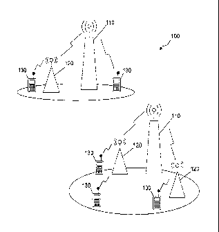
[0007] Figure 1 is a diagram illustrating a radio access network according to
an
embodiment of the disclosure.
[0008] Figure 2 is a chart of common reference signal transmission according
to an
embodiment of the disclosure.
[0009] Figure 3 is a diagram of a subframe sequence between a relay node and a
UA
according to an embodiment of the disclosure.
2
CA 02764574 2011-12-05
WO 2010/148119 PCT/US2010/038866
[0010] Figure 4 is a flowchart of an adaptive procedure 400 for reconfiguring
multicast/broadcast single frequency network subframes according to an
embodiment of
the disclosure.
[0011] Figure 5 is a chart of dedicated reference signal transmission
according to an
embodiment of the disclosure.
[0012] Figure 6 is a protocol diagram for synchronous SI broadcast according
to an
embodiment of the disclosure.
[0013] Figure 7 illustrates a processor and related components suitable for
implementing the several embodiments of the present disclosure.
DETAILED DESCRIPTION
[0014] It should be understood at the outset that although illustrative
implementations of
one or more embodiments of the present disclosure are provided below, the
disclosed
systems and/or methods may be implemented using any number of techniques,
whether
currently known or in existence. The disclosure should in no way be limited to
the
illustrative implementations, drawings, and techniques illustrated below,
including the
exemplary designs and implementations illustrated and described herein, but
may be
modified within the scope of the appended claims along with their full scope
of equivalents.
[0015] Disclosed herein are methods and systems for providing relay
transparency
requirements for wireless telecommunications systems. Accordingly, the relay
nodes may
be configured to support one of a plurality of reference signal transmission
schemes for
channel estimation and mobility measurements. In a first scheme, the relay
node, as well
as the access node may transmit a common reference signal (CRS) to a plurality
of UAs.
In a second scheme, the relay node may transmit a dedicated reference signal
(DRS) to
one of the UAs. Alternatively, the relay node may transmit a DRS to the UA for
signal
demodulation and a channel state information reference signal (CSI RS) for
channel
measurement. Additionally, the reference signal transmissions may be
configured for
multiple-input multiple-output (MIMO) channel measurements.
[0016] Figure 1 illustrates an embodiment of a radio access network (RAN) 100,
which
may be a LTE or LTE-A network as described in the 3GPP. Figure 1 is exemplary
and
may have other components or arrangements in other embodiments. In an
embodiment,
the RAN 100 may comprise at least one access device 110, at least one relay
node (RN)
120, and at least one UA 130. The access devices 110 may be an ENB, a base
station, or
3
CA 02764574 2011-12-05
WO 2010/148119 PCT/US2010/038866
other components that promote network access for the UAs 130. The access
devices 110
may communicate with any UA 130, which may be within the same cell, directly
via a direct
link. A cell may be a geographical area of reception and transmission
coverage. For
instance, the direct link may be a point-to-point link established between the
access device
110 and the UA 130 and used to transmit and receive signals between the two.
The
access devices 110 may communicate with at least some of the RNs 120, which
may be in
the same cell, via relay links or with other access devices 110. Additionally,
the access
devices 110 may communicate with other components or devices to provide for
the
components of the RAN 100 access to other networks, for instance using similar
or
different network protocols or technologies.
[0017] The RNs 120 may communicate with any UA 130 within the same cell via
access links and with the access devices 110 via relay links to establish
indirect
communications between the UAs 130 and the access devices 110. For instance,
the
access link may be a point-to-point link established to exchange signals
between an RN
120 and a UA 130 and the relay link may be a point-to-point link established
to exchange
signals between the RN 120 and the access device 110. Further, the UAs 130 may
be
moved due to handover between the cells corresponding to different access
devices 110 or
RNs 120. Hence, the UAs 130 may establish communications with the access
devices 110
via direct links or with different RNs 120 via access links. Further, the UAs
130 may
communicate with one another using the direct links established with the
access device
110 or using the access links established with the RNs 120 and the relay links
between the
RNs 120 and the access devices 110.
[0018] The RNs 120 may be used to enhance coverage within or near a cell, or
to
extend the size of coverage of a cell. Additionally, the use of a relay node
120 can
enhance throughput of a signal within a cell because the UA 130 can access the
relay
node 120 at a higher data rate or a lower power transmission than the UA 130
might use
when communicating directly with the access node 110 for that cell.
Transmission at a
higher data rate using the same amount of bandwidth creates higher spectral
efficiency
and lower power benefits for the UA 130 by consuming less battery power.
[0019] The RNs 120 may relay the signals between the UAs 130 and the access
node
110 using frequency-division duplexing (FDD) mode, where signals are received
and
transmitted at different frequencies. As such, the RNs 120 may receive and
transmit
4
CA 02764574 2011-12-05
WO 2010/148119 PCT/US2010/038866
signals at about the same time with reduced signal interference between the
received and
transmitted signals. However, transmitting and receiving the signals to the
UAs 130 and
the access nodes 110 at about the same time may be difficult due to technical
challenges
related to the transmitters, receivers, or transceivers at the RNs 120. Hence,
the RNs may
relay the signals to the UAs 130 and the access nodes 110 using time-division
duplexing
(TDD) mode, where the signals may be transmitted and received at different
transmission
time intervals (TTIs).
[0020] The RNs 120 may comprise at least one of three types of devices, Layer
One
(L1) relays, Layer Two (L2) relays, and Layer Three (L3) Relays. The LI relays
may be
repeaters that receive, amplify and retransmit signals (without
demodulation/decoding of
the signals) between the UAs 130 and the access devices 110. The L2 relays may
receive
and transmit the signals, for instance using TDD and/or FDD mode. The L2
relays may
demodulate and decode the received signals and encode and modulate the signals
before
retransmission, for instance based on radio conditions, to improve
transmission reliability.
Additionally, the L2 relays may use resource scheduling for transmitting and
receiving the
signals from the UAs 130 or the access devices 110. The L3 relays may be more
robust
devices with the capabilities of eNBs that are configured similar to the
access devices 110
or comprise at least some of the functionalities of the access devices 110,
such as radio
resource control (RRC) and resource scheduling. The L3 relays may require the
assistance of the access node to communicate with the packet core and core
network.
[0021] The RNs 120 may be Type Two (Type 11) relays, for example as described
in
3GPP RANI#56bis, which may be a L2 relay, which may communicate with the UA
and
the access node, such as eNB, within the same cell without establishing a
separate cell
and without using a separate cell ID. The Type II relays may communicate with
LTE
Release 8 UAs as well as more advanced UAs, e.g. LTE Release 9 UAs or Release
10
UAs. Additionally, the Type II relays may be transparent to the UAs, such that
the UAs 130
may communicate with the access nodes 110 via the assistance of the RN 120
without
being aware of the presence of the RNs 120. For instance, the Release 8 UAs
may
receive reference signals from the access nodes 110 while also receiving
reference signals
from the RNs 120. The reference signals may be transmitted over pre-determined
physical
resources and may be used for channel estimation for the purpose of
demodulation and
channel measurement and mobility measurements to improve communication
reliability.
CA 02764574 2011-12-05
WO 2010/148119 PCT/US2010/038866
The reference signals transmitted from the RN 120 to the UA 130 may be a CRS,
a DRS,
or a CSI RS, such as described in detail below.
[0022] Figure 2 illustrates an example of a CRS transmission 200, which may be
sent
from the RN 120 and the access node 110 to the UA 130. The CRS may comprise
the
same allocated resources (e.g. resource element (RE), transmission time
interval (TTI),
frequency, etc.) and the same signal sequence for a plurality of UAs 130 in
the cell. The
UA 130 may receive a CRS on each of its antenna ports. For instance, the UA
130 may
receive a CRS on one port, on each of two ports, or on each of four ports, as
shown in
Figure 2. The access node 110 and the RN 120 may use similar or different
antenna
configurations to transmit the CRS. For example, the access node 110 may
transmit a
CRS using four transmitters or physical antennas and the RN 120 may transmit a
CRS
using two transmitters or physical antennas. The UA 130 may receive a combined
CRS
from the two physical antennas of the RN 120 and the two physical antennas of
the access
node 110, and another CRS from the remaining two physical antennas of the
access node
110. Alternatively, the RN 120 may transmit a CRS using its two physical
antennas and
the access node 110 may transmit a CRS using two virtual antennas. The virtual
antennas
may be each obtained using antenna virtualization from the actual physical
antennas of the
access node 110. Hence, the UA 130 may receive a combined CRS from the two
physical
antennas of the RN 120 and the two virtual antennas of the access node 110. In
some
embodiments, the RN 120 may transmit a dedicated reference signal (DRS) in
addition to
the CRS, which may be intended for one of the UAs 130 in the cell.
[0023] Further, a cyclic prefix (CP) in the transmitted reference signal may
be used to
substantially compensate for any delay spread in the combined CRS from the RN
120 and
the access node 110. Since both the RN 120 and the access node 110 are located
in the
same cell, a standard CP length may be sufficient to compensate for the delay
spread.
The network components may also be further configured to reduce potential CRS
interference to the direct linked UAs 130. The UAs 130 may estimate the
combined CRS
from the access node 110 and the RN 120, and estimate precoding matrix
indicator
(PMI)/rank indication (RI) feedback based on the combined CRS.
[0024] Figure 3 illustrates a subframe sequence 300, which may be sent from
the RN
120 to the UA 130. Specifically, the subframe sequence 300 may incur
intermittent CRS
transmission from the access node 110 and the RN 120 to the UA 130. The
subframe
6
CA 02764574 2011-12-05
WO 2010/148119 PCT/US2010/038866
sequence 300 may include a first subframe 310 and a second subframe 320. The
RN 120
may transmit the first subframe 310 to the UA 130 via the access link, The RN
120 may
then receive a subframe from the access node 110 via the relay link and
transmit at about
the same time the second subframe 320 to the UA 130 via the access link. The
first
subframe 310 may comprise user information or data transmitted using a
plurality of RBs
or resource elements (REs), e.g. at different time and frequency combinations.
Specifically, the first subframe 310 may comprise a control portion 312 and a
data portion
314. The control portion 312 may comprise downlink control information,
control channels
including a PDCCH, and other control information for managing communications
and
resource allocation. The data portion 314 may comprise a physical downlink
shared
channel (PDSCH) that may also include the CRS and user data, such as voice
and/or
video data. As used herein the terms control portion and control region may be
used
synonymously.
[0025] The second subframe 320 may be a multi-media broad cast/muiticast
single
frequency network (MBSFN) subframe, which may comprise only control
information, as
described in the 3GPP TS 36.211. Specifically, the second subframe 320 may
comprise a
control portion 322 and a transmission gap portion 324. The transmission gap
portion 324
may comprise no data transmitted from the RN to the UA 130 on the access link.
During
the transmission gap, the RN 120 may receive the signal from the access node
110.
Since, the transmission gap portion 324 may not comprise a PDSCH to the UA
130, the
CRS may not be transmitted to the UA 130 in the transmission gap portion 324
of the
second subframe 320. The control portion 322 may comprise a PDCCH and a
plurality of
reference signals, such as the CRS for channel estimation and mobility
measurements.
The control portion 322 may also comprise other control channels, such as a
physical
control format information channel (PCFICH) and a physical hybrid automatic
repeat
request indicator channel (PHICH). Since the first subframe 310 and the
control portion of
the second subframe 320 but not the transmission gap of the second subframe
320 may
comprise a CRS, the UA 120 may intermittently receive a combined CRS from the
access
node 110 and the RN 120 in the first subframe 310 and the control portion in
the second
subframe 320, and may receive a CRS from the access node 110 only in the
transmission
gap of second subframe 320.
7
CA 02764574 2011-12-05
WO 2010/148119 PCT/US2010/038866
[0026] The UA 130 may be configured by the access node 110 to properly process
the
intermittent CRS transmission. For instance, the access node 110 may send the
MBSFN
subframe configuration, e.g. timing and sequence, to the UA 130. In one
embodiment, the
access node 110 may send the MBSFN subframe configuration, which may be
associated
with a RN 120 in communication with the UA 130. The UA 130 may then use the
MBSFN
subframe configuration to properly schedule the detection of the combined CRS
during the
non-MBSFN subframe communication time. The access node 110 may use dedicated
signaling to send the MBSFN subframe configuration associated with a RN 120 to
any UA
130 in communication with the RN 120 in the cell. As such, the communications
between
the remaining UAs 130 and the access node 110 or other RNs 120 may not be
affected.
For instance, during the transmission time of the MBSFN subframe between the
RN 120
and its associated UA 130, the remaining UAs 130 in the cell may continue to
estimate the
CRS from the access node 110 and/or other RNs 120.
[0027] Typically, system information (SI) broadcast signaling may be used to
transfer
the MBSFN configuration to a plurality of UAs 130 in a cell. However, to
support the
dedicated signaling of MBSFN configuration to a UA 130 associated with a RN
120 in the
cell, the RRC signaling for Release 8 UAs may be modified by adding MBSFN
configuration information to the RRC signaling messages. Specifically,
RRCConnectionSetup andlor RRCConnectionReconfguration messages may be modified
and used for dedicated signaling of the MBSFN configuration information. Such
MBSFN
configuration information may include:
MBSFN-SubframeConfigList ::= SEQUENCE (SIZE (1..maxMBSFN-Allocations))
OF MBSFN-SubframeConfig
MBSFN-SubframeConfig ::= SEQUENCE(
radioframeAllocationPeriod ENUMERATED {nl, n2, n4, n8, n16, n32},
rad ioframeAllocation Offset INTEGER (0..7),
subframeAllocation CHOICE {
oneFrame BIT STRING (SIZE(6)),
fourFrames BIT STRING (SIZE(24))
8
CA 02764574 2011-12-05
WO 2010/148119 PCT/US2010/038866
[0028] In another embodiment, the access node 110 may broadcast the MBSFN
subframe configuration for a RN 120 to all the UAs 130 in the cell, for
instance using a
system information block (SIB-2). Hence, all the UAs 130 in the cell may use
the same
MBSFN subframe configuration to estimate the CRS. As such, the RRC messages
for
Release 8 may be used with no changes to signal the MBSFN configuration to all
the UAs
130. However, by broadcasting the same MBSFN configuration, all UAs 130 in the
cell
may consider the MBSFN subframes as unavailable for estimating the CRS signal,
even
for the direct linked UAs, which may reduce the overall spectral efficiency
for
communications,
[0029] Further, the allocation of the MBSFN subframe configuration may be semi-
static,
where the access node 110 may initially specify the MBSFN subframe
configuration in SIB-
2. For instance, the SIB-2 may comprise information about the scheduling of
the MBSFN
subframes and the periodicity of the MBSFN subframes in terms of radio frames.
The
subframe period or radio frame allocation may be assigned to support
sufficient bandwidth
for data transfer between the access node 110 and the RNs 120. The access node
110
may then monitor the number of UAs 130 communicating with the RNs 120 and the
corresponding Quality of Service (QoS) requirements of the associated RBs, and
hence
reconfigure accordingly the MBSFN subframes in order to adapt to the changing
network
requirements either periodically or when needed.
10030] Figure 4 illustrates an embodiment of an adaptive procedure 400 for
reconfiguring MBSFN subframes. Specifically, the method 400 may be implemented
by
the access node 110 to monitor the network requirements and change the MBSFN
configuration to improve spectral efficiency. At block 410, the access node
110 may
determine the current number of UAs 130 in communication with the RN 120 and
configured for supporting MBSFN subframes, and the QoS or QoS Class Indicator
(QCI)
requirements of the radio bearer connections associated with the UAs 130. Such
determination may be triggered periodically or based on a request. At block
420, the
access node 110 may calculate the current spectral efficiency over the
interface between
the access node 110 and the RN 120, also referred to as Un interface. At block
430, the
access node 110 may calculate the spectral efficiency required or needed for
the Un
interface. When calculating the spectral efficiency requirement of Un, the
access node 110
may include all bandwidth requirements for transmissions to the relay nodes
and also the
9
CA 02764574 2011-12-05
WO 2010/148119 PCT/US2010/038866
bandwidth requirements for transmissions to the UAs in multi-media broadcast/
multicast
services (MBMS) transmission mode. At block 440, the access node 110 may
verify
whether there is a substantial difference between the current spectral
efficiency and the
required spectral efficiency over the Un interface. If a substantial
difference is found
between the current and required spectral efficiencies, the method 400 may
proceed to
block 460. Otherwise, the method 400 may proceed to block 450, where the
access node
110 may continue to transmit the subframes with no changes. Alternatively, at
block 460,
when the current and required spectral efficiencies are substantially
different, the access
node 110 may change the SIB-2 to reconfigure the MBSFN subframes and the
access
node 110 pages the UAs 130 configured for receiving MBSFN subframes, such as
all the
UAs associated with a SI RNTI (SI-RNTI) may be aware of the change in SI. The
access
node 110 may also include a system information modification notification in
the paging
messages. Alternatively, the access node 110 may change the system information
value
tag in the SIB-1 of the transmitted subframes to inform the UAs about the
change in SI.
[0039] In an alternative embodiment, the access node 110 may broadcast the
MBSFN
subframe configuration to all the UAs 130 in the cell, for instance using a
system
information block (SIB-2). In addition, the access node 110 may send
additional signaling
to the LTE Release 10 UAs in the cell to indicate the specific MBSFN subframes
that are
used for access node 110 transmission to the RN 120. For instance, the
additional
signaling may be sent to each LTE Release 10 UA using dedicated signaling or
may be
multicasted to the Release 10 UAs using for example a group Radio Network
Temporary
Identifier (RNTI) associated with all the LTE Release 10 UAs. The signaled
MBSFN
subframe configuration may indicate specific MBSFN subframes, which may be
used for
transmissions from the access node 110 to the RNs 120, transmissions to the
LTE
Release 10 UAs, and for LTE Release 10 UAs CRS channel estimation purposes.
[0032] Figure 5 illustrates an embodiment of a DRS transmission 500, which may
be
sent from the RN 120 and the access node 110 to one of the UAs 130, and may
comprise
a plurality of allocated resources and a signal sequence for that UA 130. The
UA 130 may
receive the combined DRS from the access node 110 and the RN 120 using an
antenna
port. For example, the UA 130 may use a fifth antenna port to receive the
combined DRS.
The access node 110 and the RN 120 may use similar or different antenna
configurations
to transmit the DRS. The DRS transmission 500 may be sent using transmission
or
CA 02764574 2011-12-05
WO 2010/148119 PCT/US2010/038866
beamforming mode 7 in Release 8 or dual layer beamforming (BF) in Release 9.
However,
using beamforming mode 7, the RN 120 may not transmit with the DRS other
system
information, paging information, PDCCH, and Random Access Response (RAR).
Further,
the DRS transmission 500 may only be sent when the access node 110 and the RN
120
transmit data to the UA 130 at about the same time.
10033] In an alternative embodiment, which may be generally be applied to both
Type
One (Type I) and Type II relay nodes or in a system comprising access nodes
without relay
nodes, the RN 120 and/or the access node 110 may send CSI RS to a UA 130 in
addition
to the DRS. Specifically, the CSI RS may be used for channel measurement and
the DRS
may be used for signal demodulation. The access node 110 and the RN 120 may
each
transmit the CSI RS using physical antennas or virtual antennas. The CSI RS
transmitted
by different physical or virtual antennas of the access nodes 110 and RNs 120
may be
orthogonal to one another by having a different CSI RS location, e.g.
different subframe
and time/frequency tones in the subframe. Additionally, each CSI RS may have a
different
sequence for different physical antennas or virtual antennas of different
access nodes 110
and RNs 120. In some embodiments, the CSI RS may have the same CSI RS location
and the same sequence for a plurality of RNs 120 or access nodes 110 if their
coverage
areas or cells do not overlap. Alternatively, if the coverage areas overlap, a
plurality of
RNs 120 or access nodes 110 may each transmit a CSI RS on a specified physical
or
virtual antenna that has the same CSI RS location and the same sequence so
that the UA
130 may receive a combined CSI RS over a composite channel.
[0034] The RN 120 may receive the CSI RS configuration to be used by the RN
120 for
transmission, e.g. the CSI RS location and sequence, from the access node 110
via
signaling. The CSI configuration may be based on the antenna configuration of
the RN
120, which may be previously signaled from the RN 120 to the access node 110,
for
example using RRC signaling. Further, the UA 130 may not be aware of such CSI
RS
information exchanged between the access node 110 and the RN 120. However,
Release
UAs 130 may still receive, from the access node 110, the CSI RS configuration
for the
antenna ports that the UA 130 is configured for detecting a CSI RS. The access
node 110
may also use signaling, e.g. RRC signaling or Media Access Control (MAC)
signaling, to
transmit the CSI RS configuration for the UA 130.
11
CA 02764574 2011-12-05
WO 2010/148119 PCT/US2010/038866
[0035] Release 10 UAs may use the CSI RS to obtain MIMO channel measurements
and hence send feedback to the access node 110 and/or the RN 120. The feedback
may
comprise a PMI and/or a channel matrix H. The channel matrix H feedback may
comprise
full channel information or some compressed channel information. The feedback
may be
used to support cooperative multipoint (CoMP) MIMO transmission as well as non-
COMP
MI MO transmission from the access node 110 or the RN 120.
[0036] In the case of non-CoMP MIMO transmissions, the access node 110 or RN
120
that transmits a PDSCH to the UA 130 may determine the precoding of the PDSCH
transmission. Alternatively, the access node 110 may determine the precoding
for the
RN's PDSCH transmission, for instance based on the PMI and/or H matrix
feedback from
the UA 130. Alternatively, Release 8 UAs may not be configured to obtain CSI
RS signals
but may still receive CRS signals for MIMO channel measurements.
[0037] In the case of CoMP MIMO transmissions, a plurality of access nodes 110
and/or RNs 120 may use joint precoding in the PDSCH across the physical
antennas
and/or virtual antennas of the plurality of access nodes 110 and/or RNs 120.
The access
nodes 110 and/or RNs 120 may transmit to the UA 130 a plurality of precoded
spatial
multiplexing layers of PDSCH data, which may be orthogonal to each other. Each
received
layer at the UA 130 may be a jointly precoded transmission from all or some of
the access
nodes 110 and/or RNs 120. A DRS for each precoded layer may also be
transmitted using
the same joint precoding as PDSCH across the physical antennas and/or virtual
antennas
for demodulation at the UA 130. In another embodiment, each of the access
nodes 110 or
RNs 120 may use a separate precoding for its set of physical antennas and/or
virtual
antennas for both PDSCH data and DRS. Each of the access nodes 110 or RNs 120
may
transmit different sets of spatial multiplexed layers to the UA 130. In this
case, the DRS for
different spatial multiplexed layers that are transmitted from different
access nodes 110 or
RNs 120 may be orthogonal to each other. Alternatively, the access nodes 100
or RNs
120 may transmit the same sets of spatial multiplexed layers to the UA 130.
Each spatial
multiplexed layer received at the UA 130 may be a superposition of the
corresponding
layer transmission from all the access nodes 110 or RNs 120 participating in
the CoMP
transmission. In this case, the DRS for a spatial multiplexed layer received
at the UA 130
may be a superposition of the DRS transmitted from the access nodes 100 and/or
RNs 120
participating in CoMP transmission for the corresponding layer. In the case
where the
12
CA 02764574 2011-12-05
WO 2010/148119 PCT/US2010/038866
access nodes 110 and/or RNs 120 transmit the same set of spatial multiplexed
layers
using different number of physical antennas, the access nodes 110 and/or RNs
120 may
establish the same number of virtual antennas using weighted linear or non-
linear
combinations of their physical antennas.
[0038] In some embodiments, at least some of the spatial multiplexed layers
from a
subset of the access nodes 110 and/or RNs 120 may partially overlap.
Accordingly, the
overlapping layers received at the UA 130 may be a superposition of the
transmissions
from that subset of access nodes 110 and/or RNs 120. Similarly, the DRS
corresponding
to each overlapping layer may be a superposition of the precoded DRS from each
one of
the subset of access nodes 110 and/or RNs 120. In some embodiments, the
network
components may be configured for coordinated beamforming, where one of the
access
nodes 110 and RN 120 may transmit a beam to the UA 130 at a time. As such, a
"beamformed" DRS may be transmitted by the access node 110 or RN 120 that
transmits
the PDSCH to the UA 130.
[0039] In an embodiment, when the RN 120 transmits a CRS, the access node 110
and
the RN 120 may simultaneously transmit data using transmit diversity, The
access node
110 and RN 120 may simultaneously transmit a plurality of control signaling
transmissions,
including broadcast channel (BCH), paging channel (PCH), PDCCH, PHICH, and
PCFICH,
which may be based on transmit diversity. When the RN 120 transmits a DRS but
not a
CRS, the access node 110 and the RN 120 may simultaneously transmit data based
on
transmission mode 7 and only the access node 110 may transmit the control
signaling
information. Further, both the access node 110 and the RN 120 may broadcast SI
across
the network, for instance in a synchronous manner, to increase broadcast
coverage. As
such, the access node 110 may send the RNs 120 registered with the access node
110
relevant system information, such as master information block (MIB) and system
information blocks (e.g. SIB-1, SIB2, etc.). Additionally, the access node 110
may inform
the RNs 120 of the scheduling of the MIB, SIB-1, and SIB-2 to SIB-11.
[0040] Figure 6 illustrates an embodiment for a synchronous SI broadcast 600,
which
may be used to transmit the SI from the access node 110 and the RNs 120.
Initially, the
access node 110, e.g. ENB, may transmit the SI information, e.g. MIB and/or
SIB-1, to the
RNs 120, e.g. RNO, RN1, and RN2. For instance, the SI information may be
received by
the RNs 120. Next, the same Si information may be broadcasted from the access
node
13
CA 02764574 2011-12-05
WO 2010/148119 PCT/US2010/038866
110 and the RNs 120 to the UA 130 (or UE) simultaneously or in a time
synchronous
manner. The UA 130 may access the system using a Physical Random Access
Channel
(RACH) preamble to the RNs 120 and the access node 110. For instance, the RACH
preamble information may be received by one of the RNs 120, e.g. RNO, and then
relayed
back to the access node 110. Additionally, each of the RNs 120 may transmit a
RACH
preamble Channel Quality Indicator (CQI) to the access node 110. The access
node 110
may use the RACH preamble and CQI to configure network resources. When the
RACH/CQI information is received by the access node 110 directly from the UA
130, the
access node 110 may wait until receiving the related RACH/CQI information
relayed by the
RN 120. The two independent signals received from the RN 120 and UA 130 may
then be
combined to improve performance.
[0041] Additionally, when the access node 110 and the RN 120 simultaneously
transmit
the paging information, PDCCH, PHICH, and PCFICH, the access node 110 may
inform
the RN 120 of the scheduling of such control information and data content and
any
physical layer parameters, such as modulation, coding, and/or rate matching
parameters.
In the case where the access node 110 and a plurality of RNs 120 transmit the
same CRS
or the same CRS and DRS to the UAs 130, the PDCCH control information may be
broadcasted in advance from the access node 110 to the RNs 120.
[0042] In an embodiment, the UA 130 may estimate composite channel conditions
and
provide feedback, such as PMI, to the RN 120 and access nodes 110, and the RN
120
may support a plurality of MIMO modes, such as spatial multiplexing, transmit
diversity,
and beamforming. The MIMO modes supported by the RN 120 may be based on the
type
of reference signal from the RN 120, i.e. CRS or DRS, for demodulation at the
UA 130.
[0043] For instance, in the case of a CRS transmission from the RN 120, the UA
130
may receive a composite channel from both the access node 110 and the RN 120.
The
UA 130 may then estimate the composite channel to select a PMI. The UA 130 may
receive a first channel matrix H1 from the access node 110 and a second
channel matrix H2
from the RN 120. The first and second channel matrices relate the received
signal R at the
UA 130 to the simultaneously or synchronously transmitted signal S from the
access node
110 and the RN 120 under a signal noise level N, such as R = (H1 + H2) * S +
N. The UA
130 may select the PMI, denoted as a precoding matrix P, based on the
composite
channel matrix H = H1 + H2. The UA 130 may send a feedback to the access node
110
14
CA 02764574 2011-12-05
WO 2010/148119 PCT/US2010/038866
comprising the precoding matrix P. The precoding matrix P may also be
determined by the
access node 110 and forwarded, for example via backhaul signaling, to the RN
120. The
access node 110 may also transmit the PMI in the PDCCH. Using the PMI or
precoding
matrix P for MIMO transmissions, the R signal may be calculated, such as R =
(Hi + H2)
P * S + N = H * P * S + N. For instance, at the receiver side, the UA 130 may
perform a
MIMO receiver algorithm, e.g. Minimum Mean Square Error (MMSE), vertical Bell
labs
layered space-time (V-BLAST), Zero Forcing (ZF), or Successive Interference
Cancellation
(SIC), to obtain the signal based on the composite channel H and the precoding
matrix P.
The RN 120 may remain transparent to the UA 130 and may not require additional
feedback from the UA 130 to support the MIMO transmission. The UA 130 may also
select
the RI and the CQI in a manner similar to the PMI selection.
[0044] In other words, a Type-II RN can transmit a CRS that is identical to
the CRS
transmitted from an access node on the same antenna port. That is, the CRS
contained in
the same PRB or RB of the same subframe on the same antenna port is identical.
The UA
130 might receive only the combined CRS on the same antenna port. That is, the
CRS
transmitted from the Type-II relay is transparent to the UA 130. When the
antenna ports
are different, the UA 130 might receive the CRS respectively from different
antenna ports.
In this case, the Type-11 relay may or may not be transparent to the UA 130.
[0045] In the case of a DRS transmission from the RN 120, the UA 130 may
receive the
composite channel H without the PMI and perform channel estimation on the
composite
DRS from both the access node 110 and the RN 120. In Release 8, the DRS may be
used
to support transmission mode 7 at the UAs. Similarly, the transmission mode 7
may also
be supported at the RN 120 to improve performance when the RN 120 transmits
the DRS
instead of the CRS. In Release 9, dual layer beamforming is proposed as an
additional
feature. In an embodiment, channel estimation for the dual layer beamforming
mode may
be supported using orthogonal DRS. The RN 120 may form or transmit its beam to
the UA
130 independently or with assistance from the access node 110. During each
transmission, the access node 110 may configure single user or multi-user
transmissions.
The RN 120 may be configured to support both transmissions either by detecting
the UA's
feedback information, e.g. RI or PMI feedback, or by receiving transmission
scheme
information from the access node 110 in advance. However, when the RN 120
transmits
the DRS instead of the CRS to support MIMO transmission, the UA 130 may send
RI or
CA 02764574 2011-12-05
WO 2010/148119 PCT/US2010/038866
PMI feedback based on the received CRS from the access node 110. As such, the
channel from the RN 120 to the UA 130 may not be considered in the feedback
information, which may cause inaccurate channel estimation and RI/PMI
selection and
hence may degrade performance. To improve performance, the UA 130 may perform
channel estimation and RI/PMI selection using the received DRS (and the CRS
from the
access node 110) and return updated RI/PM] information.
[0046] In other words, a Type-II RN can transmit a DRS that is identical to
the DRS
transmitted from an access node on the same antenna port. That is, the DRS
contained in
the same PRB or RB of the same subframe on the same antenna port is identical.
The UA
130 might receive only the combined DRS on the same antenna port. That is, the
DRS
transmitted from the Type-II relay is transparent to the UA 130. The UA 130
might
determine the PMI based on the received combined DRS, and then the UA 130 may
feed
back the determined PMI back to the access node.
[0047] Also, a Type-II RN can transmit a CSI-RS that is identical to the CSI-
RS
transmitted from an access node on the same antenna port. That is, the CSI-RS
contained
in the same PRB or RB of the same subframe on the same antenna port is
identical. The
UA 130 might receive only the combined CSI-RS on the same antenna port. That
is, the
CSI-RS transmitted from the Type-11 RN is transparent to the UA 130. When the
antenna
ports are different, the UA 130 might receive the CSI-RS respectively from
different
antenna ports. The UA 13 might make the channel measurements based on the
received
combined CSI-RS.
[0048] In an embodiment, the UA 130 may calculate the composite channel H
based on
the received signal R and the precoding matrix P for DRS transmissions,
reselect the
Rl/PMI, and forward the composite channel H and the updated RI/PMI to the
access node
110 and the RN 120. If the access node 110 overwrites the PMI from the UA 130,
channel
estimation may be degraded. However, if the access node 110 does not
frequently
overwrite the PMI from the UA 130, channel degradation may be limited.
Further, channel
estimation based on DRS transmission from the RN 120 may be combined with
channel
estimation based on CRS transmissions from the access node 110 to improve
performance.
(0049] The UA 130 and other components described above might include a
processing
component that is capable of executing instructions related to the actions
described above.
16
CA 02764574 2011-12-05
WO 2010/148119 PCT/US2010/038866
Figure 7 illustrates an example of a system 1300 that includes a processing
component
1310 suitable for implementing one or more embodiments disclosed herein. In
addition to
the processor 1310 (which may be referred to as a central processor unit or
CPU), the
system 1300 might include network connectivity devices 1320, random access
memory
(RAM) 1330, read only memory (ROM) 1340, secondary storage 1350, and
input/output
(I/O) devices 1360. These components might communicate with one another via a
bus
1370. In some cases, some of these components may not be present or may be
combined
in various combinations with one another or with other components not shown.
These
components might be located in a single physical entity or in more than one
physical entity.
Any actions described herein as being taken by the processor 1310 might be
taken by the
processor 1310 alone or by the processor 1310 in conjunction with one or more
components shown or not shown in the drawing, such as a digital signal
processor (DSP)
1302. Although the DSP 502 is shown as a separate component, the DSP 502 might
be
incorporated into the processor 1310.
[0050] The processor 1310 executes instructions, codes, computer programs, or
scripts
that it might access from the network connectivity devices 1320, RAM 1330, ROM
1340, or
secondary storage 1350 (which might include various disk-based systems such as
hard
disk, floppy disk, or optical disk). While only one CPU 1310 is shown,
multiple processors
may be present. Thus, while instructions may be discussed as being executed by
a
processor, the instructions may be executed simultaneously, serially, or
otherwise by one
or multiple processors. The processor 1310 may be implemented as one or more
CPU
chips.
[0051] The network connectivity devices 1320 may take the form of modems,
modem
banks, Ethernet devices, universal serial bus (USB) interface devices, serial
interfaces,
token ring devices, fiber distributed data interface (FDDI) devices, wireless
local area
network (WLAN) devices, radio transceiver devices such as code division
multiple access
(CDMA) devices, global system for mobile communications (GSM) radio
transceiver
devices, worldwide interoperability for microwave access (WiMAX) devices,
and/or other
well-known devices for connecting to networks. These network connectivity
devices 1320
may enable the processor 1310 to communicate with the Internet or one or more
telecommunications networks or other networks from which the processor 1310
might
receive information or to which the processor 1310 might output information.
The network
17
CA 02764574 2011-12-05
WO 2010/148119 PCT/US2010/038866
connectivity devices 1320 might also include one or more transceiver
components 1325
capable of transmitting and/or receiving data wirelessly.
[0052] The RAM 1330 might be used to store volatile data and perhaps to store
instructions that are executed by the processor 1310. The ROM 1340 is a non-
volatile
memory device that typically has a smaller memory capacity than the memory
capacity of
the secondary storage 1350. ROM 1340 might be used to store instructions and
perhaps
data that are read during execution of the instructions. Access to both RAM
1330 and
ROM 1340 is typically faster than to secondary storage 1350. The secondary
storage
1350 is typically comprised of one or more disk drives or tape drives and
might be used for
non-volatile storage of data or as an over-flow data storage device if RAM
1330 is not large
enough to hold all working data. Secondary storage 1350 may be used to store
programs
that are loaded into RAM 1330 when such programs are selected for execution.
[0053] The 1/0 devices 1360 may include liquid crystal displays (LCDs), touch
screen
displays, keyboards, keypads, switches, dials, mice, track balls, voice
recognizers, card
readers, paper tape readers, printers, video monitors, or other well-known
input devices.
Also, the transceiver 1325 might be considered to be a component of the I/O
devices 1360
instead of or in addition to being a component of the network connectivity
devices 1320.
[0054] Various combinations of the components of the system 1300, including
memory,
hardware, firmware, software or others may be referred to herein as a
"component".
[0055] The following are incorporated herein by reference for all purposes:
3GPP TS
36.814, 3GPP TS 36.304, and 3GPP TS 36.331.
[0056] In an embodiment a network is provided. The network comprising a relay
node
configured to transmit a CRS to a plurality of UAs using a first plurality of
physical antennas
and/or virtual antennas, and an access node configured to transmit a second
CRS to the
UAs using a second plurality of physical antennas and/or virtual antennas,
wherein the first
CRS and the second CRS are combined for the same number of first and second
physical
antennas and/or virtual antennas.
[0057] In another embodiment, a method is provided, comprising transmitting a
CRS to
a UA for channel measurements, and transmitting a MBSFN subframe configuration
information to the UA to schedule the CRS signal reception.
[0058] In another embodiment, a network is provided, comprising a relay node
configured to transmit a DRS to a UA using a first plurality of physical
antennas and/or
18
CA 02764574 2011-12-05
WO 2010/148119 PCT/US2010/038866
virtual antennas, and an access node configured to transmit a second DRS to
the UA using
a second plurality of physical antennas and/or virtual antennas, wherein the
first DRS and
the second DRS are transmitted at about the same time.
[0059] In another embodiment, a network is provided, comprising a relay node
configured to transmit an orthogonal CSI RS and a DRS to a UA using a
plurality of
physical antennas and/or virtual antennas, wherein the orthogonal CSI RS is
used for
channel measurement and the DRS is used for signal demodulation.
[0060] In another embodiment, a user agent is provided, comprising a plurality
of
antenna ports, and a processor configured to receive a first CRS and a second
CRS using
the antenna ports, wherein the first CRS is transmitted using a first
plurality of physical
antennas and/or virtual antennas and the second CRS is transmitted using a
second
plurality of physical antennas and/or virtual antennas, and wherein the first
CRS and the
second CRS are combined for the same number of first and second physical
antennas
and/or virtual antennas.
[0061] In another embodiment, a user agent is provided, comprising a plurality
of
antenna ports, and a processor configured to receive a first DRS and a second
DRS signal
using at least one of the antenna ports, wherein the first DRS and the second
DRS are
transmitted at about the same time.
[0062] In another embodiment, a user agent is provided, comprising a plurality
of
antenna ports, and a processor configured to receive an orthogonal CSI RS and
a DRS
transmitted fro an access node and/or relay node using at least one of the
antenna ports,
to use the orthogonal CSI RS for channel measurement, and to use the DRS for
signal
demodulation.
[0063] While several embodiments have been provided in the present disclosure,
it
should be understood that the disclosed systems and methods may be embodied in
many
other specific forms without departing from the spirit or scope of the present
disclosure.
The present examples are to be considered as illustrative and not restrictive,
and the
intention is not to be limited to the details given herein. For example, the
various elements
or components may be combined or integrated in another system or certain
features may
be omitted, or not implemented.
[0064] Also, techniques, systems, subsystems and methods described and
illustrated in
the various embodiments as discrete or separate may be combined or integrated
with other
19
CA 02764574 2011-12-05
WO 2010/148119 PCT/US2010/038866
systems, modules, techniques, or methods without departing from the scope of
the present
disclosure. Other items shown or discussed as coupled or directly coupled or
communicating with each other may be indirectly coupled or communicating
through some
interface, device, or intermediate component, whether electrically,
mechanically, or
otherwise. Other examples of changes, substitutions, and alterations are
ascertainable by
one skilled in the art and could be made without departing from the spirit and
scope
disclosed herein.