Note: Descriptions are shown in the official language in which they were submitted.
CA 02765272 2011-12-12
WO 2010/144783 PCT/US2010/038284
1
PRESTRAINED STRETCHED LAMINATES
FIELD
In general, embodiments of the present disclosure relate to stretched
laminates with
prestrained elastics. In particular, embodiments of the present disclosure
relate to stretched
laminates with prestrained elongate elastic elements for use with disposable
wearable absorbent
articles.
BACKGROUND
Absorbent articles can absorb liquid bodily exudates such as sweat, blood,
urine, menses,
etc. An absorbent article can include elastic legbands and/or an elastic
waistband.
Unfortunately, some legbands and waistbands may have a rough plastic
appearance or feel.
Some integral legbands and waistbands may not appear finished and garment-
like. And some
legbands and waistbands that only use live stretch tend to use materials
inefficiently. Also some
legbands and waistbands may not adequately conform the article to a wearer's
body. Absorbent
articles with such legbands and waistbands may look unattractive, cost more,
and perform
poorly.
BRIEF DESCRIPTION OF THE DRAWINGS
Figure 1A illustrates a front outside perspective view of a front-fastenable
wearable
absorbent article formed for wearing, wherein the article includes legbands
and waistbands,
according to embodiments of the present disclosure.
Figure 1B illustrates a back outside perspective view of the article of the
embodiment of
Figure 1A.
Figure 2A illustrates a back outside perspective view of a pant-type wearable
absorbent
article formed for wearing, wherein the article includes legbands and
waistbands, according to
embodiments of the present disclosure.
Figure 2B illustrates a back outside perspective view of the article of the
embodiment of
Figure 2A.
Figure 3A illustrates a top view of a prestrained stretched laminate with
elongate elastic
elements, wherein the laminate is pulled flat, according to embodiments of the
present
disclosure.
CA 02765272 2011-12-12
WO 2010/144783 PCT/US2010/038284
2
Figure 3B illustrates a side view of the prestrained stretched laminate of the
embodiment
of Figure 3A.
Figure 3C illustrates a top view of the prestrained stretched laminate of the
embodiment
of Figure 3A in a relaxed state, according to embodiments of the present
disclosure.
Figure 3D illustrates a side view of the prestrained stretched laminate of the
embodiment
of Figure 3C.
Figure 3E illustrates an end view of the prestrained stretched laminate of the
embodiment
of Figure 3A.
Figure 3F illustrates an end view of an alternate embodiment of a prestrained
stretched
laminate, according to embodiments of the present disclosure.
Figure 3G illustrates an end view of another alternate embodiment of a
prestrained
stretched laminate, according to embodiments of the present disclosure.
DETAILED DESCRIPTION
The embodiments of prestrained stretched laminate of the present disclosure
can be used
with all kinds of absorbent articles and disposable garments. An absorbent
article can absorb
liquid bodily exudates such as sweat, blood, urine, menses, etc. An absorbent
article can be a
product or a material. Examples of absorbent articles include products and/or
materials for
sanitary protection, hygienic use, and/or wound care.
Some absorbent articles are disposable. A disposable absorbent article is
configured to
be partly or wholly disposed of after a single use. A disposable absorbent
article is configured
such that the soiled article, or a soiled portion of the article, is not
intended to be restored and
reused (e.g., not intended to be laundered). Examples of disposable absorbent
articles include
wound care products, such as bandages and dressings, as well as feminine care
products, such as
pads and liners. Disposable absorbent articles can use embodiments of the
present disclosure.
Some absorbent articles are wearable. A wearable absorbent article is
configured to be
worn on or around a body of a wearer. Wearable absorbent articles can also be
disposable.
Examples of disposable wearable absorbent articles include disposable diapers
and disposable
incontinence undergarments. A disposable wearable absorbent article can
receive and contain
bodily exudates while being worn by a wearer. In some embodiments, a
disposable wearable
absorbent article can include a topsheet, an absorbent core, an outer cover, a
waist opening, and
leg openings. Disposable wearable absorbent articles can use embodiments of
the present
CA 02765272 2011-12-12
WO 2010/144783 PCT/US2010/038284
3
disclosure.
The embodiments of prestrained stretched laminates of the present disclosure
can be
used as a front waistband, back waistband, leg band, and/or anchoring band;
embodiments can
be used in or on a side ear, side panel, topsheet, outer cover, and/or other
suitable portions of a
wearable absorbent article, as described herein. Such prestrained stretched
laminates can be
attached to a wearable absorbent article as discrete pieces or continuous
bands, on the wearer
side, on the garment side, or interposed between layers of the article (e.g.
integral).
The figures of the present disclosure are intended to illustrate elements,
their parts, and
their relationships, as described in the specification; the figures are not
intended to illustrate any
particular relative or absolute size or dimension, unless otherwise stated in
the text.
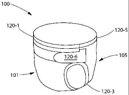
Figure 1A illustrates a front outside perspective view of a front-fastenable
wearable
absorbent article 100 formed for wearing. The article 100 has a front 101 and
a back 105. The
article includes a front waistband 120-1, legbands 120-3, a back waistband 120-
5, and side ears
120-6. Any of the front waistband 120-1, legbands 120-3, back waistband 120-5,
and side ears
120-6, or a portion thereof, can be configured to include or be formed from
any of the
embodiments of the prestrained stretched laminates of the present disclosure.
While the present disclosure refers to front-fastenable absorbent articles,
the present
disclosure also contemplates alternate embodiments of absorbent articles using
prestrained
stretched laminates, as described herein, wherein the absorbent articles are
rear-fastenable or
side fastenable. Thus, each embodiment of an absorbent article of the present
disclosure that is
described as front-fastenable can also be configured to be rear fastenable, as
will be understood
by one of ordinary skill in the art.
Figure 1B illustrates a back outside perspective view of the article of the
embodiment of
Figure 1A.
Figure 2A illustrates a back outside perspective view of a pant-type wearable
absorbent
article 200 formed for wearing. The article 200 has a front 201 and a back
205. The article
includes a front waistband 220-1, legbands 220-3, a back waistband 220-5, and
side panels 220-
8. Any of the front waistband 220-1, legbands 220-3, back waistband 220-5, and
side panels
220-8 can be configured to include or be formed from any of the embodiments of
the prestrained
stretched laminate of the present disclosure.
Throughout the present disclosure, a reference to a pant-type wearable
absorbent article
refers to an article with sufficient stretch to enable it to be readily pulled
over a wearer's hips
CA 02765272 2011-12-12
WO 2010/144783 PCT/US2010/038284
4
and buttocks while the waist and leg openings are formed. A pant-type wearable
absorbent
article can refer to an embodiment that is side-fastenable, to an embodiment
that is front-
fastenable or to an embodiment without fasteners. A reference to a pant-type
wearable
absorbent article can also refer to an article with preformed waist and/or leg
openings or to an
embodiment that is not preformed. Thus, each embodiment of an absorbent
article of the present
disclosure that is described as pant-type can be configured in any of these
ways, as will be
understood by one of ordinary skill in the art.
Figure 2B illustrates a back outside perspective view of the article of the
embodiment of
Figure 2A.
Figure 3A illustrates a top view of a prestrained stretched laminate 320. The
prestrained
stretched laminate 320 has a first inealastic layer 330-1 and a second
inelastic layer 330-2. The
first inelastic layer 330-1 is disposed subjacent to the second inelastic
layer 330-2. In various
embodiments, any of the embodiments of a prestrained stretched laminate of the
present
disclosure can also include one or more additional materials, such as
additional layers.
The prestrained stretched laminate 320 also includes a plurality of elongate
elastic
element 340 disposed between the inelastic layers 330-1 and 330-2. As used
herein, the term
elongate elastic element is intended to refer to an element with a width
greater than or equal its
thickness, and a length much greater than its width, such as strands, ribbons,
strips, and bands.
In the embodiment of Figure 3A, the elongate elastic element 340 are elastic
strands. However,
in various embodiments the elongate elastic element 340 can be other elongate
elastic elements
such as strands, ribbons, strips, and/or bands, or combinations thereof.
In Figure 3A, the prestrained stretched laminate 320 is illustrated as if the
prestrained
stretched laminate 320 is pulled flat. The prestrained stretched laminate 320
has a primary
direction 370 and a second direction 380 perpendicular to the primary
direction 370. The first
inelastic layer 330-1 and/or the second inelastic layer 330-2 has an inelastic
extensibility in the
primary direction 370. The prestrained stretched laminate 320 may or may not
have an inelastic
extensibility in the secondary direction 380 or in other directions.
As used herein, the term "extensible" refers to the property of a material (or
a composite
of multiple materials) that can extend, without substantial rupture or
breakage, to 50% in the
Hysteresis Test (as described herein). Micro-sized rupture or breakage of a
material is not
considered substantial rupture or breakage. However, macro-sized ruptures
through the
structure (e.g. one or more large tears such as tears greater than about 5
millimeters in any
CA 02765272 2011-12-12
WO 2010/144783 PCT/US2010/038284
direction, or breaking into two or more pieces, or resulting in significant
structural degradation
which may render the material unusable for its intended purpose) are
considered substantial
ruptures or breakage. A material that does not meet this definition for
"extensible" is considered
"inextensible." An extensible material may be elastic or inelastic as defined
herein.
As used herein, the term "elastic" refers to the property of an extensible
material (or a
composite of multiple materials) that can extend, without substantial rupture
or breakage, to
50% in the Hysteresis Test, with a set less than or equal to 10% of the
elongation as measured
according to the Hysteresis Test. For example, a material that has an initial
length of 25
millimeters and extends 12.5 millimeters to an extended length of 37.5
millimeters (50%
elongation) with a set of 1 millimeter (8% of the elongation), when subjected
to the Hysteresis
Test, would be considered elastic. An elastic material is considered
elastically extensible.
As used herein, the term "inelastic" refers to the property of an extensible
material (or a
composite of multiple materials) that can extend, without substantial rupture
or breakage, to
50% in the Hysteresis Test, with a set greater than 10% of the elongation as
measured according
to the Hysteresis Test. For example, a material that has an initial length of
25 millimeters and
extends 12.5 millimeters to an extended length of 37.5 millimeters (50%
elongation) with a set
of 2 millimeters (16% of the elongation), when subjected to the Hysteresis
Test, would be
considered inelastic. An elastic material is considered inelastically
extensible.
In some materials, the properties of extensibility, elasticity, and
inelasticity can be
directional. That is a material may be extensible in a first direction, but
not be extensible in a
second direction. In these cases, the material's properties would be
considered direction
dependent. The material would be considered extensible in the first direction,
but inextensible
in the second direction. Similarly, a material's elasticity or inelasticity
can also be described in
terms of a particular direction within the material.
The first inelastic layer 330-1 and/or the second inelastic layer 330-2 can be
a sheet of
material formed from film (such as a polyolefin film), nonwoven, foam, scrim,
a natural fiber
(e.g. cotton), or combinations thereof. The sheet can be formed from one layer
of material, or
several layers of material, such as a laminate. As an example, inelastic
layers can be a linear
low density polyethylene film with a basis weight of 18 grams per square meter
(gsm).
The first inelastic layer 330-1 and/or the second inelastic layer 330-2 can be
formed from
separate sheets or from a single sheet folded over onto itself. The first
inelastic layer 330-1
and/or the second inelastic layer 330-2 can be liquid impermeable or liquid
permeable. The first
CA 02765272 2011-12-12
WO 2010/144783 PCT/US2010/038284
6
inelastic layer 330-1 and/or the second inelastic layer 330-2 can be vapor
impermeable or vapor
permeable. In various embodiments, the inelastic layers can be permeable by
their construction,
or rendered permeable by aperturing.
Each of the elongate elastic elements 340 has an elastic extensibility along
its length.
Each of the elongate elastic elements 340 is substantially parallel with the
primary direction 370.
As a result, each of the elongate elastic elements 340 provides elastic
extensibility to the
prestrained stretched laminate 320 in the primary direction 370. In various
embodiments, the
elongate elastic elements 340 can be completely parallel with the primary
direction 370.
The elongate elastic elements 340 can be formed from various materials, such
as Lycra,
rubber, Spandex, styrene ethylbutylene styrene, styrene ethylene propylene
styrene, styrene
ethylene ethylene propylene styrene, styrene butadiene styrene, styrene
isoprene styrene,
polyolefin elastomers, elastomeric polyurethanes, rubbers, similar materials,
and combinations
thereof. In some embodiments, the elongate elastic elements 340 can be
extruded strand
elastics. As an example, the elongate elastic elements 340 can be 1240 decitex
soft Spandex. In
various embodiments, any or all of the elongate elastic elements 340 can have
a decitex ranging
from 540 to 1580, or any integer value for any decitex value in this range, or
any range formed
by any of these integer values.
As used herein, the term prestrained is intended to refer to one or more
elastic elements
in an extended state. Prestrain is measured from an initial length of the
element, wherein the
elastic element is under enough tension to remove any slack but not so much
tension as to
elastically extend the element. For example, when an elongate elastic element
is prestrained
10%, the element is extended to 110% of its initial length.
Each of the elongate elastic elements 340 is attached to the inelastic layers
330-1 and
330-2 while prestrained at least 10% in the primary direction 370 relative to
the inelastic layers
330-1 and 330-2, to form a precursor laminate of elastic and inelastic
elements. This attachment
of prestrained elastics can be accomplished in various ways. As a first
example, while the
inelastic layer is not extended, elongate elastic elements can be prestrained
10% and then
applied to the inelastic layer. As a second example, while the elastic layer
is extended, the
elongate elastic elements can be prestrained to match the elastic layer's
extension, plus
prestrained an additional 10% and then applied to the inelastic layer.
In various embodiments, one or more of the elongate elastic elements 340 can
be
attached to the inelastic layers 330-1 and 330-2 at a prestrain of at least
10%, at least 25%, at
CA 02765272 2011-12-12
WO 2010/144783 PCT/US2010/038284
7
least 50%, at least 75%, at least 100%, at least 150%, at least 200%, or any
integer prestrain
value among any of these percentages, or any range formed by any of these
integer values. Each
of the elongate elastic elements 340 can be attached at the same prestrain, or
at differing
prestrains. Alternatively, one or more of the elongate elastic elements 340
can be attached at
zero or substantially zero prestrain.
As used herein, the term extended is intended to refer to one or more elastic
and/or
inelastic elements in an extended state. Extension is measured from an initial
length of the
element(s), wherein the element(s) are under enough tension to remove any
slack but not so
much tension as to inelastically extend any inelastic elements. For example,
when a laminate of
elastic and inelastic elements is extended 25%, the laminate is extended to
125% of its initial
length. Extension is measured macroscopically (i.e. with respect to the
overall length of the
element(s)) and is not intended to measure local variations in extension, such
as those caused by
friction lock.
After the elongate elastic elements 340 are attached, the precursor laminate
is extended at
least 35% in the primary direction 370 to form the prestrained stretched
laminate 320. It should
be noted that, as part of this extension, the inelastic portion of the
precursor laminate is extended
inelastically. The extension can be accomplished in various ways, such as by
stretching the
laminate between several pairs of nip rolls with each pair running at a higher
speed compared to
the previous one, incremental stretching, or other activation techniques, such
as ring-rolling.
The extension process can be applied to the laminate while the laminate is in
a relaxed state,
while the laminate is under tension to remove slack, or while the laminate is
under a process
tension. It is contemplated that the extension process can be applied to the
laminate before the
laminate is attached to an article or after the laminate is attached to the
article. In various
embodiments, the extension can be accomplished using a profiled activation
process, such as
those described in US patent application entitled "Process for Activating a
Web", filed
November 19, 2007 and published as US publication 20090127742.
In the embodiment of Figure 3A, the prestrained stretched laminate 320 is
illustrated as
including a plurality of tooth marks 362 from an intermeshing of teeth in an
activation-type
stretching process. As an example, the extension can be accomplished with
intermeshing teeth
having 0.100" pitch, with a 2.7 millimeter depth of engagement. In various
embodiments, the
precursor laminate can be extended, in the primary direction, at least 50%, at
least 75%, at least
100%, at least 150%, at least 200%, at least 250%, at least 300%, or any
integer extension value
CA 02765272 2011-12-12
WO 2010/144783 PCT/US2010/038284
8
among any of these percentages, or any range formed by any of these integer
values. The
precursor laminate may or may not be extended in the secondary direction 380,
or any other
direction, before or after attachment to an article.
When the prestrained stretched laminate 320 is under enough tension to remove
any
slack but not so much tension as to further inelastically extend the inelastic
layers 330-1 and
330-2, the prestrained stretched laminate 320 has an overall extended length
372, measured in
the primary direction 370, and an overall extended width 382, measured in the
secondary
direction 380. In the embodiment of Figure 3A, the overall extended length 372
is much greater
than the overall extended width 382, resulting in the prestrained stretched
laminate 320 with an
overall rectangular shape; however this is not required and the prestrained
stretched laminate
320 can be configured in various other shapes, e.g. via curving the
prestrained stretched laminate
on an article or folding or cutting it to shape it.
For the prestrained stretched laminate 320, the overall extended width 382 is
determined
by the overall width of the inelastic layers 330-1 and 330-2. The overall
extended width 382 is
somewhat narrower than the original overall width of the inelastic layers 330-
1 and 330-2, since
the inelastic extension in the primary direction 370 may cause neckdown in the
secondary
direction 380. The amount of necking will depend on the properties of the
inelastic layers 330-1
and 330-2 and the nature of the inelastic extension. As an example, the
inelastic layers 3301-
and 330-2 may experience necking that results in a 5-25% reduction in their
overall width.
In various embodiments of waist and leg bands, the prestrained stretched
laminate 320
can have an overall extended width 382 that is at least 5 millimeters, at
least 10 millimeters, at
least 15 millimeters, at least 20 millimeters, at least 30 millimeters, at
least 40 millimeters, at
least 50 millimeters, or any integer value in millimeters among any of these
dimensions, or any
range formed by any of these integer values. For a stretchable outer cover, a
side ear, or a side
panel made from a prestrained stretched laminate, these dimensions may be
substantially larger;
for example, a stretchable outer cover made from the laminate could have the
dimensions of the
full length and width of the diaper.
The prestrained stretched laminate 320 has a laminate elastic extensibility
that is the
product of the prestrain of the elongate elastic elements 340 producing a fore-
shortened relaxed
state and the inelastic extension induced in the inelastic layers, corrected
for the small amount of
set in the elastic material as it goes through these transformations. For
example, in a prestrained
stretched laminate where the elastics have been prestrained 10% and the
inelastic layers have
CA 02765272 2011-12-12
WO 2010/144783 PCT/US2010/038284
9
been extended of 25%, the laminate elastic extensibility is calculated at 1.10
times 1.25, yielding
a result of 1.38, with the assumption that percent set is small and can be
neglected; so the
example prestrained stretched laminate would have a laminate elastic
extensibility of 38%.
Further examples are shown in Table 1, shown below.
Table 1
PRESTRAIN OF ELASTIC ELEMENTS
10% 20% 30% 40% 50% 60% 70% 80% 90% 100%
20% 32% 44% 56% 68% 80% 92% 104% 116% 128% 140%
25% 38% 50% 63% 75% 88% 100% 113% 125% 138% 150%
30% 43% 56% 69% 82% 95% 108% 121% 134% 147% 160%
40% 54% 68% 82% 96% 110% 124% 138% 152% 166% 180%
50% 65% 80% 95% 110% 125% 140% 155% 170% 185% 200%
60% 76% 92% 108% 124% 140% 156% 172% 188% 204% 220%
70% 87% 104% 121% 138% 155% 172% 189% 206% 223% 240%
80% 98% 116% 134% 152% 170% 188% 206% 224% 242% 260%
EXTENSION 90% 109% 128% 147% 166% 185% 204% 223% 242% 261% 280%
OF 100% 120% 140% 160% 180% 200% 220% 240% 260% 280% 300%
INELASTIC 110% 131% 152% 173% 194% 215% 236% 257% 278% 299% 320%
ELEMENTS 120% 142% 164% 186% 208% 230% 252% 274% 296% 318% 340%
130% 153% 176% 199% 222% 245% 268% 291% 314% 337% 360%
140% 164% 188% 212% 236% 260% 284% 308% 332% 356% 380%
150% 175% 200% 225% 250% 275% 300% 325% 350% 375% 400%
160% 186% 212% 238% 264% 290% 316% 342% 368% 394% 420%
170% 197% 224% 251% 278% 305% 332% 359% 386% 413% 440%
180% 208% 236% 264% 292% 320% 348% 376% 404% 432% 460%
190% 219% 248% 277% 306% 335% 364% 393% 422% 451% 480%
200% 230% 260% 290% 320% 350% 380% 410% 440% 470% 500%
It should be noted that the results in Table 1 are based on the assumption of
no set. Any
set would increase the initial dimension and thus reduce the elasticity of the
prestrained stretched
laminates.
In various embodiments, a prestrained stretched laminate can have a laminate
elastic
extensibility, in the primary direction, with elastic extensions of at least
35%, at least 50%, at
least 100%, at least 200%, at least 300%, at least 400%, at least 500%, at
least 600%, or any
integer value among any of these percentages, or any range formed by any of
these integer
values.
Figure 3B illustrates a side view of the prestrained stretched laminate 320 of
the
CA 02765272 2011-12-12
WO 2010/144783 PCT/US2010/038284
embodiment of Figure 3A. The prestrained stretched laminate has an overall
extended thickness
392.
Figure 3C illustrates a top view of the prestrained stretched laminate 320 of
the
embodiment of Figure 3A in a relaxed state (with the elongate elastic elements
340 contracting
the prestrained stretched laminate 320) after the prestrained stretched
laminate 320 has been
extended in the primary direction 370. The prestrained stretched laminate 320
has an overall
relaxed length 376 in the primary direction 370 and an overall relaxed width
386 in the
secondary direction 380. Without wishing to be bound by this theory, it is
believed that when
the prestrained stretched laminate 320 is released from the extending process
and the prestrained
stretched laminate 320 is relieved of the forces causing the inelastic
extension, the elongate
elastic elements 340 contract the inelastic layers 330-1 and 330-2, which, in
turn, buckle out of
the plane defined by the primary direction 370 and the secondary direction
380, resulting in a
plurality of shirrs 332, with each of the shirrs oriented in the secondary
direction and
contributing to an overall relaxed thickness 396 of the prestrained stretched
laminate 320.
Figure 3D illustrates a side view of the prestrained stretched laminate 320 of
the
embodiment of Figure 3C. In some embodiments, the overall relaxed thickness
396 can vary
from 1 mm, to 2 mm, to 3 mm, to 4 mm, to 5 mm, or larger. These measurements
of overall
relaxed thickness are taken under a pressure of 0.2 psi. This pressure is
intended to flatten the
relaxed prestrained stretched laminate without causing significant deformation
and
bending/collapsing of the shirrs. The shirrs 332 form a regular undulating
pattern of shirrs
alternating up and down, which tends to give the prestrained stretched
laminate 320 a high-
quality textile-like appearance. As a result, an absorbent article that
includes the prestrained
stretched laminate 320 can look attractive. The overall relaxed thickness 396
also gives the
prestrained stretched laminate 320 a gentle resiliency to pressure applied
from above the
prestrained stretched laminate 320, which tends to give the prestrained
stretched laminate 320 a
soft feel. As a result, an absorbent article that includes the prestrained
stretched laminate 320
can be tactilely pleasing. In various embodiments, either or both of the
inelastic layers 330-1
and 330-2 can be treated with further processing, such as abrading, embossing,
hydro-
aperturing, vacuum-aperturing, and the addition of fibers, in order to further
improve the soft
feel of the outer surfaces of the prestrained stretched laminate 320. It is
contemplated that any
of these processes can be performed before or after the laminate is
inelastically extended.
Despite the presence of the shirrs 332, the prestrained stretched laminate 320
as a whole
CA 02765272 2011-12-12
WO 2010/144783 PCT/US2010/038284
11
still tends to lie flat in its relaxed state; that is, the prestrained
stretched laminate 320 does not
experience large scale buckling that causes the prestrained stretched laminate
320 as a whole to
curl up off of a surface on which it is resting. This provides good
processability for the
prestrained stretched laminate 320. Without wishing to be bound by this
theory, it is believed
that the prestrained stretched laminate 320 can be configured to obtain a
beneficial regular
pattern of shirrs 332 without undesirable large scale buckling, by selecting
appropriate spacings
of the elongate elastic elements 340. Throughout the present disclosures, all
spacing
measurements for elongate elastic elements are measured to the center of the
element. In some
embodiments, the spacing between any two adjacent elongate elastic elements
340 can be
selected from the group including 1 millimeter, 2 millimeters, 3 millimeters,
4 millimeters, 5
millimeters, 6 millimeters, or a greater distance. or any range formed by any
of these values..
In various embodiments, either or both of the first inelastic layer 330-1 and
the second
inelastic layer 330-2 can be white or can include a colored tinting of any
color and any level of
opacity. Either or both of the inelastic layers 330-1 and 330-2 can be
transparent to reveal the
underlying elongate elastic elements 340 and to create a visual effect of an
elastic like waistband
for the observer. One or more outer layers of a prestrained stretched laminate
may also be
printed to further enhance the appearance of softness and garment-like
texture. Any of these
design features may be combined with others to alter or enhance the appearance
of the
prestrained stretched laminate 320 and/or an absorbent article including such
a laminate.
Also, one or more of the elongate elastic elements 340 can be white or can
include a
colored tinting, of any color. In some embodiments, the inelastic layers 330-1
and 330-2 and the
elongate elastic elements 340 can have matching colors. In other embodiments,
the inelastic
layers 330-1 and 330-2 and the elongate elastic elements 340 can have
contrasting colors. Such
contrasting colors may be desirable, in order to simulate the appearance of a
line of stitching in a
cloth material. In various embodiments, the color of the inelastic layers 330-
1 and 330-2 and/or
the elongate elastic elements 340 may contrast or match other portions of an
article to which the
prestrained stretched laminate 320 is attached.
Figure 3E illustrates an end view of the prestrained stretched laminate 320 of
the
embodiment of Figure 3A. In the embodiment of Figure 3E, the inelastic layers
330-1 and 330-
2 are in contact with each other across the overall extended width 382, except
where the contact
is interrupted by the elongate elastic elements 340. In some embodiments, it
may be desirable to
affect a mechanical attachment between part or all of the inelastic layers 330-
1 and 330-2. For
CA 02765272 2011-12-12
WO 2010/144783 PCT/US2010/038284
12
example, the left side edge of the prestrained stretched laminate 320 or the
right side edge of the
prestrained stretched laminate 320, or both side edges may be sealed. The
sealing may assist in
keeping the elongate elastic elements 340 captured between the inelastic
layers 330-1 and 330-2
and may also provide a more finished appearance to the prestrained stretched
laminate 320.
Alternatively, in one or more of the spaces between the elongate elastic
elements 340 and/or the
spaces between the elongate elastic elements 340 and the side edges, the
inelastic layers 330-1
and 330-2 may be mechanically connected with various techniques, applied
either to the
prestrained stretched laminate 320 by itself or, applied as the prestrained
stretched laminate 320
is being bonded to an absorbent article.
While the elongate elastic elements 340 are illustrated as elastic strands
having a round
cross-section, elongate elastic elements can have various cross-sectional
shapes.
The plurality of elongate elastic elements 340 includes a first elastic strand
340-1, a
second elastic strand 340-2, and a third elastic strand 340-3. However, in
various embodiments,
a prestrained stretched laminate 320 can include 1-10 strands, or any number
of strands in this
range.
The first elastic strand 340-1 is located a first spaced apart distance 382-1
in the
secondary direction 380 from the left side edge of the prestrained stretched
laminate 320. The
second elastic strand 340-2 is located a second spaced apart distance 382-2 in
the secondary
direction 380 from the first elastic strand 340-1. The third elastic strand
340-3 is located a third
spaced apart distance 382-3 in the secondary direction 380 from the second
elastic strand 340-2.
The third elastic strand 340-3 is also located a fourth spaced apart distance
382-4 in the
secondary direction 380 from the right side edge of the prestrained stretched
laminate 320.
The first spaced apart distance 382-1 may be the same as or different from the
second
spaced apart distance 382-4, and these distances can be selected from the
group including 2
millimeters, 3 millimeters, 4 millimeters, 5 millimeters, 6 millimeters, or a
greater distance, or
any range formed by any of these values. Either or both of the spaced apart
distances 382-1 and
382-4 may be the same as or different from either or both of the spaced apart
distances 382-2
and 382-3. The spaced apart distance 382-2 may be the same as or different
from the spaced
apart distance 382-3, and can be selected from the group including 2
millimeters, 3 millimeters,
4 millimeters, 5 millimeters, 6 millimeters, 7 millimeters, 8 millimeters, 9
millimeters, 10
millimeters, or a greater distance, or any range formed by any of these
integer values. Any of
these distances can be uniform or varying. Any of these distances can be used
with any other
CA 02765272 2011-12-12
WO 2010/144783 PCT/US2010/038284
13
dimensions described herein.
Each of the elongate elastic elements 340 is attached to the inelastic layers
330-1 and
330-2. In the embodiment of Figure 3E, each of the elongate elastic elements
340 is attached
continuously along its length, however, in some embodiments, the attachment
may be
discontinuous. The attachment of the elongate elastic elements 340 can be
accomplished in
various ways. As an example, a slot coating of adhesive can be applied between
the inelastic
layers 330-1 and 330-2, and across all of the elongate elastic elements 340.
As another example,
adhesive can be slot coated onto the elongate elastic elements 340, with a
slot for each of the
elements. As a further example, adhesive can be applied as a spiral wrap on
each of the elongate
elastic elements 340. For instance, such adhesive spiral wraps can be applied
with the
SureWrapTm process using equipment available from the NordsonC) Corporation.
Also,
adhesive can be applied using the OmegaTm pattern from ITWC). As still a
further example, the
elongate elastic elements 340 can be coextruded with one or both of the
inelastic layers 330-1
and 330-2. The present application contemplates that the elongate elastic
elements 340 can also
be attached in various other ways known in the art. These attachment
techniques can be
similarly applied to embodiments with elastic ribbons or sheets, as will be
understood by one of
skill in the art.
Figure 3F illustrates an end view of another alternate embodiment of a
prestrained
stretched laminate 321 in an extended state, according to embodiments of the
present disclosure.
The prestrained stretched laminate 321 of the embodiment of Figure 3F is
configured in the
same way as the prestrained stretched laminate 320 of the embodiment of Figure
3E, except that
the prestrained stretched laminate 321 does not include a second inelastic
layer. Otherwise, the
prestrained stretched laminate 321 includes a first inelastic layer 331-1
configured in the same
general way as the first inelastic layer 330-1 of the embodiment of Figure 3E,
and elastic strands
341-1, 341-2, and 341-3 are configured in the same general way as the elongate
elastic elements
340-1, 340-2, and 340-3 of the embodiment of Figure 3E.
As an example, a prestrained stretched laminate can include one inelastic
layer that is
combined with elongate elastic elements using a slot coat application of
adhesive. In this
embodiment, any exposed adhesive tack can be neutralized by the application of
powders such
as calcium carbonate or cornstarch. Any excess powder could be vacuumed off to
create a
single layer laminate. Alternatively, fibers (natural or synthetic) could be
flocked to an adhesive
layer coating just the elongate elastic elements or to the entire surface of a
laminate with one
CA 02765272 2011-12-12
WO 2010/144783 PCT/US2010/038284
14
inelastic layer.
Figure 3G illustrates an end view of another alternate embodiment of a
prestrained
stretched laminate 322 in an extended state, according to embodiments of the
present disclosure.
The prestrained stretched laminate 322 of the embodiment of Figure 3G is
configured in the
same way as the prestrained stretched laminate 321 of the embodiment of Figure
3F, except that,
in the prestrained stretched laminate 322, the elongate elastic elements are
set within recessed
portions formed within the inelastic layer 331-2. Otherwise, the prestrained
stretched laminate
322 includes a first inelastic layer 331-2 configured in the same general way
as the first inelastic
layer 331-1 of the embodiment of Figure 3F, and elastic strands 342-1, 342-2,
and 342-3 are
configured in the same general way as the elastic strands 341-1, 341-2, and
341-3 of the
embodiment of Figure 3F.
The embodiments of prestrained stretched laminates of the present disclosure
can be
attached to absorbent articles in various positions. An edge of a prestrained
stretched laminate
can coincide with part or all of an edge of a chassis of a wearable absorbent
article. For
example, when a prestrained stretched laminate is used as a waistband in a
wearable absorbent
article, an edge of the laminate can coincide with part or all of an edge of a
chassis that forms a
waist opening in the article. As another example, when a prestrained stretched
laminate is used
as a legband, an edge of the laminate can coincide with part or all of an edge
of a chassis that
forms a leg opening in the article. An edge of a prestrained stretched
laminate can coincide with
part or all of an edge of a wearable absorbent article by positioning the
laminate with respect to
the article, or by trimming the laminate (after the laminate is attached), or
by trimming the
laminate and the article together (after the laminate is attached). As an
alternative example,
when a prestrained stretched laminate is used as a legband, an edge of the
laminate can extend
out beyond part or all of an edge of a chassis that forms a leg opening in the
article.
The embodiments of prestrained stretched laminates of the present disclosure
can be
attached to absorbent articles using various methods. For example, prestrained
stretched
laminates can be attached to wearable absorbent articles by using adhesive,
ultrasonic bonding,
bonding with heat and/or pressure, or other kinds of bonding, or combinations
of any of these
methods.
The embodiments of prestrained stretched laminates of the present disclosure
can be
used in front-fastenable and/or pant-type disposable wearable absorbent
articles, as described
below. In an exemplary embodiment, a pant-type disposable wearable absorbent
article can
CA 02765272 2011-12-12
WO 2010/144783 PCT/US2010/038284
include: an elastically extensible outer cover; a bucket-shaped core assembly
including a liquid
impermeable polyolefin film, a liquid permeable body side liner, and an
absorbent core
therebetween; a waist band; and leg bands. In variations of this exemplary
embodiment, part,
parts, substantially all, or all of the elastically extensible outer cover can
be elastic. In a first
variation, the article may be elastically extensible in a front waist region
and a back waist region,
but not in a crotch region. In a second variation, the article may be
elastically extensible in its
four side panel regions, but not in other regions. In a third variation, the
article may be
elastically extensible along one or more longitudinal stripes that run from
the front of the article
to the back of the article, but not in an area defined by the absorbent core.
Embodiments of a disposable wearable absorbent article of the present
disclosure can
include any of the various outer covers disclosed herein. A cloth-like outer
cover may be a
single layer of material or a laminate of two or more layers of material. The
outer cover may
include a base layer configured as an outer, wearer-facing side of the outer
cover and the
absorbent article. The base layer may be configured to be a relatively thin,
low basis weight
layer, which contributes to a relatively lightweight, thin outer cover. For
example, the base layer
may have a basis weight of between 10 and 50 g/m2. The base layer may be
configured to have
a caliper of between 0.05 and 1 mm, under a pressure of 2100 Pascals. Calipers
for both film
and nonwoven materials described herein may be determined according to ASTM
D5729-97
(2004), titled "Standard Test Method for Thickness of Nonwoven Fabrics." The
base layer may
be selected to provide a soft, cloth-like feel and may include one or more
extensible nonwoven
materials. For example, the base layer may be formed from a single layer of
spunbond and/or
meltblown polyolefin fibers (e.g., a polyethylene-containing nonwoven or any
other suitable
material known in the art). In certain embodiments, the base layer may include
one or more
webs of polypropylene/polyethylene blends. Blends of polyethylene and
polypropylene may be
provided in any suitable weight % based on the weight of the blend. For
example, a blend may
include weight percent ratios of 30/70, 50/50, 60/40, 70/30, 80/20
(polypropylene/polyethylene).
The blends may be in the form of core/sheath-type bicomponent fibers (i.e.,
fibers that have an
outer sheath of a first composition surrounding an inner core of a second
composition) or side-
by-side bicomponent fibers. Nonwovens made of polypropylene/polyethylene
core/sheath
bicomponent fibers may be configured to provide a web having a desired
combination of
softness, strength, and extensibility. The ratio of polypropylene and
polyethylene in the core
and sheath can be tailored to give the desired properties. One particularly
suitable example of
CA 02765272 2011-12-12
WO 2010/144783 PCT/US2010/038284
16
material for use as a soft, outer base layer is a spunbond nonwoven made from
core/sheath type
bicomponent fibers that include 70% polypropylene in the core and 30%
polyethylene in the
sheath, available from Fiberweb plc, Simpsonville, SC under the trade name
SOFTEX. The
base layer may also be a spunbond web comprising polypropylene or polyethylene
monocomponent fibers. In another example, the base layer may be a spunbond-
meltblown-
spunbond polyolefin fibrous web that includes mono and/or bicomponent fibers.
In yet another
example, the base layer may include a monocomponent or bicomponent carded web.
The outer cover may also include an elastic layer. The elastic layer may be
joined to the
base layer by any means known in the art, e.g., adhesive bonding, ultrasonic
bonding, thermal
calendar bonding, high pressure bonding. The elastic layer may be intermittent
(i.e.,
discontinuous) in one or more directions. For example, a longitudinally
intermittent elastic layer
may be present in a portion of one or both waist regions of the outer cover,
but absent in at least
a portion of the crotch region. In certain embodiments, the elastic layer may
be coextensive with
one or both waist regions in the longitudinal and/or lateral direction. In
certain embodiments,
the intermittent elastic layer may be formed from a single piece (or laminate)
of elastic material
that is substantially coextensive with only the body portion of one or both
waist regions. In
certain embodiments, a laterally intermittent elastic layer may be present in
a portion of one or
both side panel regions of an outer cover, but absent in at least a portion of
the body region
inboard of the side panel regions. In certain embodiments, the intermittent
elastic layer may be
both longitudinally and laterally intermittent. In certain embodiments, the
elastic layer may be
present as one or more elastic strips that extend laterally across the outer
cover in a portion of
one or both waist regions. The elastic layer may extend partially into the
crotch region,
however, it may be desirable to limit the extent to which the elastic layer
extends into the crotch
region to, e.g., limit the cost of producing the outer cover. The elastic
layer may be exemplified
as an elastic film, however, it is to be understood that the elastic layer may
include one or more
layers of elastic film(s), elastic nonwoven(s), and/or elastic strand(s), or
laminates of elastic
materials and extensible materials. For example, the elastic layer may be a
bilaminate formed
by joining the elastic layer to an extensible nonwoven layer, and then
subjecting the bilaminate
to an activation process to enable the laminate, for example, to stretch in at
least the lateral
direction. Alternatively or additionally, the bilaminate may be joined to the
base layer and then
subjected to an activation process. In another example, the elastic layer may
be configured as a
trilaminate, in which an elastic material layer is sandwiched between two
extensible nonwoven
CA 02765272 2011-12-12
17
layers, or between a nonwoven layer and a film layer. As with the bilaminate
example, the
trilaminate may be subjected to an activation process before, during, and/or
after being joined to
the base layer. Certain elastic materials suitable for use herein may have
some amount of "tack"
(i.e., stickiness), and thus may exhibit undesirable characteristics when
wound onto and/or
unwound from a roll (e.g., high unwind force and/or relatively noisy). In
order to at least
partially reduce the tendency of the tacky elastic material to stick to itself
when wound onto a
roll, another material (e.g., nontacky polymeric material) may be disposed on
the surface(s) of
the elastic material to act as a so-called "skin." The skin may at least
partially mask the
undesirable tackiness of the elastic material. It may be desirable to provide
a relatively thin,
lightweight outer cover, and therefore suitable basis weights for the elastic
layer described
herein may range from e.g., 10 to 100 grams per square meter ("gsm"), 15 to 75
gsm, or even 20
to 50 gsm. The skin basis weight may be from 2-10 gsm or 3-5 gsm. Suitable
elastic layer
calipers may range from, e.g., 0.01 to 0.1 mm. One particularly suitable
example of an elastic
material for use in the outer cover 500 is a 25 gsm elastic polypropylene film
comprising
VISTAMAXX, an elastomeric polypropylene resin available from ExxonMobil
Chemical,
Houston, TX.
Because the elastic layer is generally not present in at least a portion of
the crotch region
of the outer cover, the structural integrity, opacity, and/or other
characteristics of the outer cover
in the crotch region may be undesirably impacted. To compensate for any such
deficiencies, the
basis weight of the outer cover base layer may be increased, but as pointed
out above this may
undesirable increase manufacturing costs and/or diminish the clarity and
vibrancy of the
graphics. Therefore, it may instead be desirable to include a reinforcing
member disposed
generally in the crotch region of the outer cover, as disclosed in US
published application 2010-
0228212, filed on March 5, 2009, entitled "Outer Cover for a Disposable
Absorbent Article". In
various embodiments, bonding of the core bucket to a stretchable outer cover
can be
accomplished with a shaped bond area, as disclosed in US published application
2010-0298802,
filed on May 19, 2009, entitled "Attachment Areas for Wearable Absorbent
Articles".
Preparation of Samples for Hysteresis Test
To obtain a sample of an individual component (e.g. an elastic element or an
inelastic
layer) of a prestrained stretched laminate, when the component is available as
separate material,
CA 02765272 2011-12-12
WO 2010/144783 PCT/US2010/038284
18
prior to being attached to another component and/or formed in the laminate,
cut each sample as
described below. For sheet material, such as films and nonwovens used in an
inelastic layer, cut
each sample to be 5.5 cm long in the primary direction and the same width as
the laminate when
it is attached to the article. For elongate elastic elements, cut each sample
to be 5.5 cm long,
creating as many elongate elastic elements as there are in the prestrained
stretched laminate. If
the prestrained stretched laminate has different numbers of elongate elastic
elements in different
portions, then use the largest number of elongate elastic elements present in
any of the portions.
When placing the elongate elastic elements in the grips of the tensile tester
the elements are
placed adjacent to each other. When reporting the data for elongate elastic
elements, use the
laminate width, which is the width of the prestrained stretched laminate when
it is attached to
the article, to calculate load in N/cm.
To obtain a sample of an individual component of a prestrained stretched
laminate, when
the individual component is only available as part of the laminate attached to
the chassis of a
disposable wearable absorbent article, carefully remove each sample from the
product, if
possible, using any technique known to one skilled in the art. For example, if
the laminate is
adhered to the chassis, then freeze the adhesive bond and carefully peel the
laminate from the
chassis, while taking care to ensure that layers of the laminate do not become
separated from one
another. Then, if possible, separate the elastic and inelastic elements. If it
is not possible to
separate a prestrained stretched laminate from a chassis or to separate
elastic and inelastic
elements without tearing or significantly damaging them, then those materials
cannot be tested
with this method.
To obtain a sample of a prestrained stretched laminate when the laminate is
available as a
separate structure, prior to being attached to the chassis of a disposable
wearable absorbent
article, cut each sample to be 5.5 cm long in the primary direction and the
same width as the
laminate when it is attached to the article.
To obtain a sample of a prestrained stretched laminate when the laminate is
only
available as attached to the chassis of a disposable wearable absorbent
article, carefully remove
each sample from the product, if possible, using any technique known to one
skilled in the art.
For example, if the laminate is adhered to the chassis, then freeze the
adhesive bond and
carefully peel the laminate from the chassis, while taking care to ensure that
layers of the
laminate do not get separated from one another. If it is not possible to
separate a prestrained
stretched laminate from a chassis without tearing or significantly damaging
them (e.g. if the
CA 02765272 2011-12-12
WO 2010/144783 PCT/US2010/038284
19
laminate is mechanically bonded to the chassis), then those materials cannot
be tested with this
method.
To obtain a sample of a prestrained stretched laminate in combination with a
portion of
the chassis underlying the prestrained stretched laminate, to which the
laminate is attached, use
one of the following procedures, depending on whether the laminate is used as
a waist band or
leg band.
When the prestrained stretched laminate is used as a waistband, to obtain a
sample of the
laminate in combination with the portion of the chassis, use one of the
following procedures, as
applicable. For a laminate that is a waistband on a pant-type disposable
wearable absorbent
article without fasteners and having a side seam, cut the article open at the
side seam (cut in the
middle for an overlap seam or cut along an inboard edge for a butt seam). For
a laminate that is
a waistband on a pant-type disposable wearable absorbent article without
fasteners and having a
front or back seam, cut the article open on the sides so that the width of the
article in the front
and in the back are the same. For a laminate that is a waistband on a front-
fastenable disposable
wearable absorbent article or on a refastenable pant-type disposable wearable
absorbent article,
wherein the fastener can be opened, open up the fasteners, and lay the opened
article out with
the outer cover facing upward and the topsheet facing downward (the article
may or may not lie
completely flat).
For each embodiment described above, to obtain a sample of the laminate as a
waistband
in combination with the portion of the chassis, use the following procedure.
Without stretching
the article, remove the entire back waistband from the chassis along with any
portion of the
chassis adhered to it. Accomplish this by cutting along the length of the
waistband, ensuring
that the sample is the same width as the prestrained stretched laminate. On
the removed
waistband, mark a line 15 mm laterally in from the terminal edge. Mark a
second line 45 mm in
from the terminal edge and cut the waistband along this line to obtain a
sample 45 mm in length.
If a 45 mm length is not available, a lesser length may be used, provided
there is enough
material to hold in the grips of the tensile tester at the 15 mm gauge length.
Use this procedure
to obtain two samples of the combination, one from each end of the removed
waistband. If the
length of the waistband is less than 90 mm, but greater than 45 mm, obtain
samples from two
separate articles, one from the right side, the other from the left.
When the prestrained stretched laminate is used as a legband, to obtain a
sample of the
laminate in combination with the portion of the chassis, use the following
procedure. Without
CA 02765272 2011-12-12
WO 2010/144783 PCT/US2010/038284
stretching the article, remove the entire legband from the chassis along with
any portion of the
chassis adhered to it. Accomplish this by cutting along the length of the
legband, ensuring that
the sample is the same width as the prestrained stretched laminate. On the
removed legband
identify the midpoint along the length of the sample. Measuring from the
midpoint, mark a line
22.5 mm to both sides of this midpoint. Measuring from one of these lines
towards the
midpoint, mark a third line at 15 mm. Cut along the first two lines to obtain
a sample 45 mm in
length. Repeat this procedure for the other legband, to obtain two samples of
the combination
from the article.
Hysteresis Test
The Hysteresis Test can be used to various specified strain values, as
described herein.
The Hysteresis Test utilizes a commercial tensile tester (e.g., from Instron
Engineering Corp.
(Canton, MA), SINTECH-MTS Systems Corporation (Eden Prairie, MN) or
equivalent)
interfaced with a computer. The computer is used to control the test speed and
other test
parameters and for collecting, calculating, and reporting the data. The tests
are performed under
laboratory conditions of 23 C 2 C and relative humidity of 50% 2%. The
samples are
conditioned for 24 hours prior to testing.
Test Protocol
1. Select the appropriate jaws and load cell. The jaws must have flat
surfaces and
must be wide enough to fit the sample (e.g., at least 2.54 cm wide). Also, the
jaws should
provide adequate force to ensure that the sample does not slip during testing.
The load cell is
selected so that the tensile response from the sample tested is between 25%
and 75% of the
capacity of the load cell used.
2. Calibrate the tester according to the manufacturer's instructions.
3. Set the distance between the grips (gauge length). For a prestrained
stretched
laminate or components thereof, the distance is 25 mm. For a prestrained
stretched laminate in
combination with an underlying portion of a chassis, the distance is 15 mm.
4. Place the sample in the flat surface of the jaws such that the primary
direction of
the sample is substantially parallel to the gauge length direction. Mount the
sample in the upper
grip, let the sample hang slack, then close the lower grip. For the
combination samples removed
from an article, mount the sample such that the 15 mm line on the sample is
aligned with the
bottom edge of the upper grip. For elongate elastic elements, take as many
elements as there are
CA 02765272 2011-12-12
WO 2010/144783 PCT/US2010/038284
21
in the laminate sample, place them adjacent to each other, and grip them in
between the jaws of
the tensile tester. Set the slack preload at 0.02 N/cm. This means that the
data collection starts
when the slack is removed (at a constant crosshead speed of lOmm/min) with a
force of 0.02
N/cm. Strain is calculated based on the adjusted gauge length (lim), which is
the length of the
sample in between the grips of the tensile tester at a force of 0.02 N/cm.
This adjusted gauge
length is taken as the initial sample length, and it corresponds to a strain
of 0%. Percent strain at
any point in the test is defined as the change in length divided by the
adjusted gauge length
times 100.
6(a). First cycle loading: Pull the sample to the specified strain at a
constant cross head
speed of 100 mm/min. , Report the stretched sample length between the jaws as
lmax.
6(b). First cycle unloading: Hold the sample at the specified strain for 30
seconds and
then return the crosshead to its starting position (0% strain or initial
sample length, 1,m) at a
constant cross head speed of 100 mm/min. Hold the sample in the unstrained
state for 1 minute.
6(c). Second cycle loading: Pull the sample to the specified strain at a
constant cross
head speed of 100 mm/min.
6(d). Second cycle unload: Next, return the crosshead to its starting position
(i.e. 0%
strain) at a constant cross head speed of 100 mm/min.
A computer data system records the force exerted on the sample during the test
as a
function of applied strain. From the resulting data generated, the following
quantities are
reported (note that loads are reported as force divided by the width of the
sample and do not take
into account the thickness of the sample):
1. Length of sample between the grips at a slack preload of 0.02 N/cm (1,m)
to the
nearest 0.001 mm.
2. Length of sample between the grips on first cycle at the specified
strain (lmax) to
the nearest 0.001 mm.
3. Length of sample between the grips at a second cycle load force of 0.02
N/cm
(lex,) to the nearest 0.001 mm.
CA 02765272 2011-12-12
WO 2010/144783 PCT/US2010/038284
22
Dimension Method
Various dimensions and ratios thereof are specified herein. Each dimension is
measured
according to the following method. All testing is performed in a conditioned
room maintained
at about 23 C 2 C and about 50% 2% relative humidity. Herein, width and
length of the
specimen are a lateral width and longitudinal length as defined herein.
Precondition specimens
at about 23 C 2 C and about 50% 2% relative humidity for 2 hours prior to
testing.
Prepare the article for testing as follows:
1. Lay the article on a substantially flat, horizontal surface.
2. Secure the article to the surface such that all process-induced contraction
acting to
forshorten the absorbent core assembly is pulled out. For example, a pre-
contracted waistband
applied to the article or elastics along the longitudinal edges of the article
and/or the absorbent
core assembled may forshorten the article laterally or respectively
longitudinally, so any such
process-induced contraction is pulled out. The article is secured to the flat,
horizontal surface
with clamps or adhesive tape capable of holding the absorbent core assembly
with process-
induced contraction pulled out.
3. Identify points between which widths and/or lengths of each attachment
region, the
absorbent core assembly, any unattached areas, and the article are to be
measured, per
definitions contained herein. This includes defining the hip region.
4. Measure each needed dimension to the nearest 1 mm using a steel ruler
traceable to
NIST.
5. Calculate any needed ratios as follows: Ratio = 100% X [First Measurement /
Second
Measurement].
Test Data
Samples 1-6, described below, were tested according to the Test Protocol of
the
Hysteresis Test with 50% as the specified stain (variations noted below) and
the resulting
percent set is reported in Table 2. Each of the Samples 1-6 was obtained as
described in the
Preparation of Samples section, above.
Sample 1 is a portion of a disposable wearable absorbent article comprising an
elastic
outer cover, an externally attached waistband that is a prestrained stretched
laminate of the
present disclosure, a bucket-shaped absorbent core assembly, and overlap seams
on the sides.
CA 02765272 2011-12-12
WO 2010/144783 PCT/US2010/038284
23
Sample 1 is the prestrained stretch laminate of the waistband in combination
with a portion of
the chassis. Four samples of Sample 1 were tested.
Sample 2 is a portion of a disposable wearable absorbent article comprising an
elastic
outer cover, an externally attached legband that is a prestrained stretched
laminate of the present
disclosure, a bucket-shaped absorbent core assembly, and overlap seams on the
sides. Sample 2
is the prestrained stretch laminate of the legband in combination with a
portion of the chassis.
Four samples of Sample 2 were tested.
Sample 3 is a portion of the prestrained stretched laminate that is used in
the waistband
and legband of Samples 1 and 2. The Sample 3 laminate is 15 mm wide and has
three strands of
1240 decitex Soft Spandex laminated between two layers of a polyethylene film
obtained from
Clopay, Mason, Ohio. This lamination was done with 1.5 mg/m/strand of H2401
adhesive
obtained from Bostik, Wauwatosa, WI, using the SureWrap glue application
procedure. Three
samples of Sample 3 were tested.
Sample 4 comprises the strands used in Samples 1, 2, and 3. Three samples of
Sample 4
were tested.
Sample 5 is the polyethylene film (18 gsm) used in Samples 1, 2, and 3. Three
samples
of Sample 5 were tested.
Sample 6 is a portion of another prestrained stretched laminate. The Sample 6
laminate
is 15 mm wide and has 3 strands of 1100 decitex Spandex laminated between two
layers of a
polyethylene film obtained from Swanson Plastics, China. This lamination was
done with 1.5
mg/m/strand of H2401 adhesive obtained from Bostik, Wauwatosa, WI, using the
SureWrap
glue application procedure. Three samples of Sample 6 were tested.
Sample 7 is the polyethylene film (24 gsm) was used in Sample 6. Three samples
of
Sample 7 were tested.
Table 2
Sample Percent Set
Mean Std. dev.
1 4.0 1.1
2 5.0 1.3
3 2.5 0.0
CA 02765272 2013-11-25
24
4 2.9 0.5
13.9 0.7
6
7 11.1 0.1
The dimensions and values disclosed herein are not to be understood as being
strictly
limited to the exact numerical values recited. Instead, unless otherwise
specified, each such
dimension is intended to mean both the recited value and a functionally
equivalent range
surrounding that value. For example, a dimension disclosed as "40 mm" is
intended to mean
"about 40 mm."
The citation of any document, including any cross referenced or related patent
or
application, is not an admission that it is prior art with respect to any
invention disclosed or
claimed herein or that it alone, or in any combination with any other
reference or references,
teaches, suggests or discloses any such invention. Further, to the extent that
any meaning or
defmition of a term in this document conflicts with any meaning or definition
of the same term
in a document cited herein, the meaning or definition assigned to that term in
this document
=
shall govern.
While particular embodiments of the present invention have been illustrated
and
described, it would be obvious to those skilled in the art that various other
changes and
modifications can be made without departing from invention described herein.