Note: Descriptions are shown in the official language in which they were submitted.
CA 02765282 2015-03-18
1
Medical Lancet
An incessant aim in the development of lancets is to allow
taking samples while minimizing pain as far as possible.
The object of the present invention is to show a way how
this aim can be reached even better.
A lancet according to the invention has a flat shank
comprising a top side and a bottom side, these two sides
being connected to each other via narrow sides extending
in the longitudinal direction of the shank. Such a shank
can, for example, be made from sheet metal with low effort
and expenditure. At a forward end, the shank of a lancet
according to the invention forms a blade which ends in a
point. The blade has at its bottom side two cutting edges
which converge in the point. On the bottom side, the shank
comprises at least one recess for taking a sample.
Preferably, this recess is configured as a groove. In the
stead or in addition to a groove, recesses having other
CA 02765282 2011-12-12
2
shapes, for example blind holes, can be arranged on the bottom
side of the shank.
In a lancet according to the invention, the blade is delimited
on the top side by two edges which converge in a vertex. As seen
in cross-section, the top side of the blade is convex between
the vertex and the forward end. This means that the blade has a
convex top side between the vertex and the forward end, as seen
transversely to the longitudinal direction.
The special shape of a blade according to the invention allows
puncturing with less pain than this is possible with the lancets
known from WO 2005/084545 Al, the blade of which are delimited
by plane surfaces and a single upper edge which extends
perpendicular to the longitudinal direction of the shank.
The surprisingly advantageous properties of a lancet according
to the invention can probably be attributed to the fact that the
formation of painful pressure waves can be avoided to the
greatest possible extend during a puncture. When a lancet
according to the invention penetrates into a patient's body
tissue, a puncture channel is produced that is gently expanded
to the thickness of the lancet shank by the convex top side of
the blade. Since the blade is delimited by two converging edges
on the top side and, as seen in cross-section, the top side of
the blade is convex between the vertex and the forward end, the
puncture channel is, initially, expanded to the full thickness
of the lancet shank only over a part of its width. While the
lancet penetrates further, the puncture channel is then enlarged
to the full thickness of the lancet shank over an increasingly
larger part of its width. This is an essential improvement as
compared with the lancet known from WO 2005/084545 Al, where the
CA 02765282 2011-12-12
3
puncture channel, when reachireg the full thickness, is also
expanded to the full width at the same time.
Since the thickness and width of a lancet are finite, it cannot
be avoided that, when a puncture is made, pressure is also
exerted on surrounding tissue transversely to the puncture
direction. In a lancet according to the invention, this pressure
is, advantageously, practically exclusively exerted from the
convex top side of the blade and the top side of the shank
arranged adjacent thereto. This probably results in that the
tissue resting against the bottom side of the shank is
compressed to a lesser degree, for which reason body fluid can
leak from the tissue resting against the bottom side of the
shank particularly easily and can fill the recess which is
provided on the bottom side of the shank for the purpose of
taking a sample.
An advantageous refinement of the invention provides that the
blade is concave along a line extending from the vertex to the
forward end. This measure contributes to further reducing the
pain connected with the puncture. That is to say that, in this
manner, the thickness of the blade, initially, increases only
relatively slowly and, subsequently, more rapidly, as seen from
the point. Therefore, the thickness of the blade is reduced in a
front region. It is assumed that, in the event of a puncture of
the lancet, body tissue initially puts up increased resistance
which declines while the lancet advances. With a blade having a
shape according to the invention, the force a lancet requires to
penetrate into body tissues is, advantageously, reduced and,
therefore, the pain sensation as well. Preferably, the blade of
a lancet according to the invention is concave in longitudinal
direction and convex in transverse direction.
CA 02765282 2011-12-12
4
Just as is the case with the point, the vertex is, preferably,
disposed in the center of the width of the shank. It is,
however, also possible that the vertex and/or the point are/is
arranged offset from the center, with the result that the two
cutting edges or the two upper edges of the blade comprise
different lengths. In such a case, the line from the vertex to
the forward end does not extend exactly in the longitudinal
direction of the shank but at a slightly slanted angle in
relation thereto.
A further advantageous refinement of the invention provides that
the upper edges of the blade extend further to the rear than the
cutting edges. In this manner, the pain connected with a
puncture can be further reduced. Therein, the blade is,
preferably, delimited by lateral edges which connect the rear
end of a cutting edge to the rear end of one of the upper edges.
Preferably, the lateral edges enclose an acute angle with a
bottom edge of the shank that extends behind the blade, wherein
said angle can, for example, range from 10 to 600, particularly
from 15 to 35 .
A further advantageous refinement of the invention provides that
the recess provided for taking a sample is configured as a
groove. Preferably, this groove ends at a distance from the
forward end of the shank, particularly between the vertex and
the forward end of the shank. Most preferably, the groove has a
section which is arranged between the cutting edges and in which
the cross-sectional area of the groove decreases towards the
forward end. The cross-sectional area of the groove can decrease
in the area of the blade by a reduction in the width or the
depth of the groove, preferably in both the width and the depth.
Preferably, the cross-sectional area, i.e., the width and/or the
depth, decreases along a length that is in excess of the maximum
CA 02765282 2011-12-12
width of the groove. In this manner, the groove can come up
nearer to the forward end of the blade without the mechanical
stability of the blade being impaired.
,
At the end of the groove, the thickness of the blade is,
preferably, less than two thirds, preferentially, no more than
half the thickness of the shank. At the end of the groove, the
width of the blade is, most preferably, less than two thirds,
preferentially, no more than half the width of the shank. Behind
the blade, the depth of the groove is, preferably, more than
half the thickness of the shank.
Usually a fluid transport by means of capillary forces requires
that the capillary cross-section does not increase because
penetration of a fluid into an increasing capillary means that
the boundary surface between fluid and air increases and is,
therefore, unfavorable from an energetic point of view. For this
reason, it could be assumed that a tapering section of the
groove is not able to contribute to taking a sample.
Surprisingly, however, this is not the case. When the groove has
a cross-sectional area that decreases towards the end of the
blade, the puncture depth required for taking a sample can be
reduced. For this reason, taking a sample with a lancet
according to the invention is, advantageously, connected with
less pain.
Therefore, the aspect of the invention that provides a groove on
the bottom side of the lancet, the cross-sectional area of which
decreases towards the forward end, also has an independent
importance. For this reason, the present invention also relates
to a lancet with a flat shank which has a top side and a bottom
side wherein, at a forward end, the shank forms a blade which
ends in a point, the blade comprises two cutting edges on the
CA 02765282 2011-12-12
6
bottom side, said cutting edges converging in the point, and the
shank comprises at least one groove for taking a sample on its
bottom side, wherein the groove comprises a section arranged
between the cutting edges, the cross-sectional area of the
groove decreasing towards the forward end in said section.
Preferably, the cross-sectional area decreases along a length
which is in excess of the width of the groove, more preferably
in excess of the thickness of the shank, particularly in excess
of the width of the shank.
A lancet according to the invention having a groove for taking a
sample that is arranged on the bottom side of the shank is also
to particular advantage in that the danger of an obstruction of
the groove or an impairment of a hydrophilic coating contained
in the groove is reduced.
Preferably, a lancet according to the invention is produced from
metal, preferably from steel. Therein, use is made of a strip of
sheet metal for the shank of the lancet. The blade and one or a
plurality of recesses for taking a sample can be formed by
etching, preferably by wet chemical etching. To achieve this, a
strip of sheet metal can be coated with photoresist on all
sides. By exposing and, subsequently, washing off the
photoresist in an appropriate manner, the latter can be removed
from the bottom side at those points where it is intended to
form the at least one recess for taking a sample. On the top
side, the photoresist can be removed in the complete region in
front of two V-shaped lines which will, subsequently, form the
upper edges of the blade. In addition, the photoresist can be
removed at the narrow sides in the region in front of a line
that extends from top to bottom and, subsequently, forms a
lateral delimiting edge of the blade. By the subsequent action
of an etching agent, the shape of the blade according to the
CA 02765282 2011-12-12
7
invention can be produced. As an alternative, however, a lancet
according to the invention can, for example, be produced by
means of laser beam cutting.
Advantageously, a lancet according to the invention allows
taking a sample from beneath the skin. The danger of a
contamination on the skin surface can, therefore, be avoided.
This is to important advantage, particularly in the
determination of the glucose concentration, because sugar is
often found on the skin, for example after the consumption of
sweet desserts. To be able to take a subcutaneous sample,
advantageous use can be made of puncturing devices with which
the return movement of the lancet is made more slowly than the
advance movement. Devices with suitable puncturing drives are
described in EP 1 709 906 Al and US 2008/0262388 Al.
One aspect of the present invention, therefore, relates to a
puncturing system with a lancet according to the invention and a
puncturing device which, on puncturing, causes an advance
movement of the lancet and a subsequent return movement wherein
the return movement takes place at a lower speed than the
advance movement. In a first section of the return movement, the
lancet is, preferably, withdrawn at a faster speed than in a
subsequent second section. In this manner, the lancet only
remains in pain-sensitive body tissue for as short a time as
possible, however, stays in pain-insensitive body tissue, for
example, the stratum corneum layer of the epidermis, for a
prolonged period of time for sample taking purposes.
A lancet according to the invention can be formed such that, in
the event of a puncture through body tissue, its blade is
deflected transversely to the puncture direction and bent
towards its bottom side. During the return movement, a cavity
CA 02765282 2011-12-12
8
will then form between the bottom side of the blade and the
tissue, said cavity being quickly filled with body fluid. During
the slow return movement or during the slow section of the
return movement, the recess arranged on the bottom side of the
lancet can, advantageously, receive a sample. The formation of a
cavity between the bottom side of the blade and surrounding body
tissue can also be caused or promoted by a shift in or
compression of tissue occurring during the puncture.
For this reason, a lancet that is bent during the puncture and
comprises a recess for taking a sample on its bottom side allows
taking a sample in an improved manner. One aspect of the
invention, which may also have an independent importance,
therefore relates to a lancet with a flat shank which has a top
side and a bottom side wherein, at a forward end, the shank
forms a blade which ends in a point, the blade comprises two
cutting edges on the bottom side, said cutting edges converging
in the point, and the shank comprises at least one recess for
taking a sample on its bottom side, wherein the shank comprises
a bending stiffness of less than 0.1 kNmm2 (kilonewton
multiplied by square millimeters), preferably less than 0.05
kNmm2, more preferably 0.03 to 0.001 kNmm2.
The bending stiffness is the product from the modulus of
elasticity of the material and the second moment of area of the
lancet shank. In a shank with a rectangular cross-section, the
second moment of area is I = a3b/12 where a is the shank
thickness and b is the shank width. In a flat lancet with a
rectangular cross-section, the second moment of area and,
therefore, the bending stiffness is somewhat reduced because of
the groove.
CA 02765282 2014-04-24
9
Preferably, the shank is made of metal, more preferably of
steel. As an alternative, however, use can also be made of
plastic. Preferably, the shank has a width of less than
0.5 mm, for example between 0.2 mm and 0.4 mm. Preferably,
the thickness of the shank is no more than 0.3 mm, more
preferably between 0.2 mm and 0.05 mm, most preferably
between 0.20 mm and 0.08 mm.
In accordance with one aspect of the present invention,
there is provided a lancet comprising a flat shank having
a top side and a bottom side, the shank forming a blade at
a forward end, the blade terminating in a point, the blade
having two cutting edges at the bottom side, the cutting
edges converging in the point, and the shank having on its
bottom side at least one recess for receiving a sample,
wherein the shank turns into the blade on the top side at
two edges which converge in a vertex, and wherein the top
side of the blade is curved convexly between the vertex
and the forward end, as seen in cross-section.
In accordance with another aspect of the present
invention, there is provided a puncturing system
comprising a lancet and a puncturing device that, during a
puncture, causes a forward motion of the lancet and
subsequently a retracting motion, wherein the retracting
motion is slower than the forward motion.
Further details and advantages of the invention are
illustrated by means of exemplary embodiments with
reference being made to the enclosed drawings. Therein,
equal and corresponding parts are designated with
consistent reference symbols. In the drawings,
Fig. 1 is a bottom view of an exemplary embodiment of a
lancet according to the invention;
CA 02765282 2014-04-24
9a
Fig. 2 is a lateral view of Figure 1;
Fig. 3 is a top view of the lancet shown in Figure 1; Fig.
4 is an inclined view of the lancet;
Fig. 5 is a cross-sectional view taken from intersection
line AA of Figure 3;
Fig. 6 is a cross-sectional view taken from intersection
line BE of Figure 3;
Fig. 7 is a cross-sectional view taken from intersection
line CC of Figure 3;
Fig. 8 is a cross-sectional view taken from intersection
line DD of Figure 3;
CA 02765282 2011-12-12
Fig. 9 is a cross-sectional view taken from intersection line
EE of Figure 3;
Fig. 10 is a cross-sectional view taken from intersection line
FF of Figure 3;
Fig. 11 is a cross-sectional view taken from intersection line
GG of Figure 3;
Fig. 12 shows an exemplary embodiment of a lancet according to
the invention while puncturing a sterile protective foil;
Fig. 13 shows an exemplary embodiment of a lancet according to
the invention on a carrier tape;
Fig. 14 shows a further exemplary embodiment of a lancet
according to the invention;
Fig. 15 is a sectional view of Fig. 14;
Fig. 16 shows a further exemplary embodiment of a lancet
according to the invention;
Fig. 17 is a sectional view of Fig. 16;
Fig. 18 shows a further exemplary embodiment of a lancet
according to the invention; and
Fig. 19 shows a sectional view of Fig. 18.
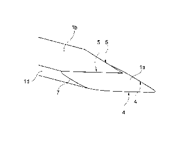
The lancet that is shown schematically in Figures 1 to 11 has a
flat shank 1 which, at its forward end, forms a blade la which
CA 02765282 2011-12-12
11
ends in a point 2. The shank 1 has a bottom side lb that is
shown in Figure 1 and a top side lc that is shown in Figure 3.
The bottom side lb and the top side lc are connected to each
other via narrow sides id extending in the longitudinal
direction of the shank 1.
On its bottom side lb, the shank 1 comprises a recess 3 for
taking a sample. Preferably, this recess 3 is configured as a
groove. It is, however, also possible to use a plurality of
recesses which are, for example, arranged as tapped blind holes
on the bottom side lb.
The blade la has two lower edges which converge in the point 2.
These lower edges are configured as cutting edges 4. In the
exemplary embodiment shown, the cutting edges 4 converge in a
wedgelike manner and enclose an acute angle. Preferably, the
cutting edges 4 enclose an angle of less than 60 , preferably of
less than 45 , more preferably an angle of less than 40 .
Preferably, the angle enclosed between the two cutting edges 4
is at least 20 , more preferably at least 25 .
In addition to the two cutting edges 4, the blade la has two
upper edges 5 which converge in a vertex 6. On the top side lc,
the blade la is, therefore, delimited by the two upper edges 5
that converge in a wedgelike manner and, on the bottom side lb,
by the cutting edges 4 that converge in a wedgelike manner. In
the exemplary embodiment shown, the upper edges 5 and the
cutting edges 4 extend in parallel but can also enclose
different angles. Preferably, the upper edges 5 enclose an acute
angle. In the exemplary embodiment shown, this angle is less
than 60 , for example, 10 to 50 , particularly 20 to 45 .
CA 02765282 2011-12-12
12
Preferably, the vertex 6 is arranged behind the point 2 by more
than the thickness of the shank 1. Therefore, the component of
the distance between the vertex 6 and the point 2, i.e., the
forward end point of the lancet, said component being measured
in the longitudinal direction of the shank 1, preferably is more
than the thickness of the shank 1. As is the case with the
exemplary embodiment shown, the vertex 6 is, preferably,
arranged behind the point 2 by more than twice the thickness of
the shank 1. Preferably, the width of the shank 1 is two to
three times its thickness.
The upper edges 5 extend further to the rear than the cutting
edges 4. On each of its sides, the blade la is laterally
delimited by an edge 7 which connects the rear end of a cutting
edge 4 to the rear edge of an upper edge 5. Preferably, the edge
7 encloses an acute angle with the lower edge of the narrow side
id arranged on its side, for example an angle between 100 and
60 , more particularly between 15 and 35 . The edge 7 can
enclose an obtuse angle with the cutting edge 4 arranged on its
side.
Therein, Figure 2 shows that the blade la is concave along a
line extending from the vertex 6 to the forward end 2. The top
side lb has an undercut at the vertex 6.
Figures 5 to 11 show a series of cross-sections of the lancet
along the intersection lines shown in Figure 3. Therein, Figure
is a sectional view taken from intersection line AA, Figure 6
taken from intersection line BB, Figure 7 taken from
intersection line CC, Figure 8 taken from intersection line DD,
Figure 9 taken from intersection line EE, Figure 10 taken from
intersection line FF, and Figure 11 taken from intersection line
GG.
CA 02765282 2011-12-12
13
Figures 5 to 7 show that the top side of the blade la is convex
between the vertex 6 and the forward end point 2, as seen in
cross-section. Therein, Figures 5 to 7 also show that the
cutting edges 4 comprise a cutting angle that decreases towards
the forward end 2. Therein, the cutting angle decreases
continuously towards the forward end 2. As a result, the
puncture channel produced in a patient's body tissue in the
event of a lancet puncture becomes thicker or wider in a
continuous manner, this being advantageous for a puncture with
reduced pain.
Figures 8 to 10 show that the blade la has concave lateral
surfaces 8 behind the vertex 6, particularly between the vertex
6 and the rear end of the cutting edges 4.
The bottom side lb of the shank 1 is plane or concave. Therein,
Figures 5 to 11 show that the bottom side lb of the shank 1,
particularly the bottom side of the blade la, is plane in a
marginal region on either side. Exclusive of the recess 3 for
taking a sample, the complete bottom side lb of the shank 1 is
plane. As a result of the recess 3, the bottom side lb of the
shank 1 is concave in the corresponding region.
In a lancet according to the invention, the bottom side lb
between the forward end 2 and the vertex 6 or even the complete
bottom side of the blade la can be free from recesses 3 for
taking a sample. Preferably, however, the recess 3 also extends
in the region of the blade la. In order to minimize the puncture
depth required for obtaining a sample, it is usually
advantageous if the recess 3 extends on the bottom side lb into
the region between the vertex 6 and the forward end 2. In order
to not impair the mechanical stability of the blade la, it is,
CA 02765282 2011-12-12
14
in general, advantageous if the groove 3 ends at a distance from
the forward end 2. Such a groove 3 that is arranged on the
bottom side lb of the shank is to advantage in that it is not
obstructed by the material of a sterile protective foil when the
latter is punctured.
In the exemplary embodiment shown, the groove 3 extends beyond
the vertex 6. Therein, Figure 1 shows that the groove 3
continuously tapers in a section in the region of the blade la.
Therein, the length of the tapering section is in excess of the
maximum width of the groove 3. In the complete tapering section,
the depth of the groove 3 continuously decreases towards the
forward end. In other words, the cross-sectional area of the
groove 3 decreases in the section arranged between the cutting
edges 4.
Preferably, the maximum width of the groove 3, i.e., the groove
width behind the blade la, is less than half the shank width.
Preferably, the maximum depth of the groove, i.e., the groove
depth behind the blade la, is in excess of half the shank
thickness. The shank thickness should be less than 0.3 mm and,
preferably, is between 80 pm and 200 pm, more preferably between
80 pm and 180 pm. For example, the shank width can be between
0.2 mm and 0.5 mm, preferably 250 pm to 400 pm.
The preferred material is steel, particularly stainless steel.
The bending stiffness of the lancet shank should not exceed 0.1
kNmm2, preferably be less than 0.05 kNmm2, more preferably less
than 0.02 kNmm2. Advantageous values range, in particular, from
0.01 to 0.001 kNmm2.
Lancets with such a low bending stiffness are elastically bent
when puncturing body tissue. Therein, the bottom side of the
CA 02765282 2011-12-12
lancet that comprises the groove 3 is the inner surface of the
bend, with the result that, when the lancet is withdrawn, a
cavity is formed on the bottom side and, therefore, in the
vicinity of the groove 3, said cavity being filled with body
fluid. For this reason, taking a sample is improved by the
bending of the lancet.
Figure 12 shows an exemplary embodiment of a lancet according to
the invention while a sterile protective foil 10 is punctured.
The sterile protective foil 10 can, for example, be a metal
foil, particularly an aluminum foil, a plastic foil or a metal
foil coated with plastic or a metal-coated plastic foil. For
example, a chamber of a lancet magazine can be closed with such
a sterile protective foil 10, in order to protect a lancet
arranged therein against harmful environmental influences.
Since, in a lancet according to the invention, the groove 3 for
taking a sample is arranged on the bottom side of the shank, the
groove 3 is not impaired when the sterile protective foil 10 is
punctured. That is to say that the cutting edges 4 of the lancet
cause the sterile protective foil 10 to be cut open on the
bottom side of the lancet in parallel to the bottom side of the
shank, with the result that the formation of foil residues which
might obstruct the groove 3 are counteracted. It is also to
advantage that parts of the punctured sterile protective foil 10
are prevented from projecting into the interior region of the
groove 3 during puncturing and, by sliding along a surface of
the groove 3, from impairing a hydrophilic coating that,
preferably, exists there.
Instead of arranging a lancet according to the invention in a
magazine chamber closed with a sterile protective foil 10, it is
also possible to arrange lancets according to the invention on a
carrier tape side by side, as this is, for example, known from
CA 02765282 2011-12-12
16
WO 2008/083844 Al. Preferably, a lancet according to the
invention is arranged on a carrier tape with its top side while
its bottom side is covered by a sterile protective foil. Figure
13 is a sectional view of an appropriate exemplary embodiment
with a carrier tape 11, a lancet and a sterile protective foil
10.
The sterile protective foil 10 is thinner than the carrier tape
11, preferably no more than half the latter's thickness. The
sterile protective foil 10 rests loosely on the lancet and is
connected to the carrier tape 11 in a substance-to-substance
bonded manner, for example glued or welded. The lancet shank 1
can be glued to the carrier tape 11 in a rear region that is
remote from the blade la. In a front region, the lancet shank 1,
preferably, rests loosely on the carrier tape 11, with the
result that, in order to make a puncture, the blade la can be
freed from the sterile protective foil by bending the carrier
tape 11, as this is described in WO 2008/083844 Al.
Figure 14 shows a further exemplary embodiment of a lancet and
Fig. 15 is a related sectional view taken from intersection line
HH. This lancet differs from the lancet shown in Figures 1 to 11
in that the recess 3 for taking a sample is configured as a
groove that is somewhat wider. This allows taking increased
sample volumes.
Figure 16 shows a further exemplary embodiment of a lancet and
Fig. 17 is a related sectional view taken from intersection line
KK. This lancet differs from the exemplary embodiment of Figures
14 and 15 in that, instead of a single recess 3 configured as
groove, there are two recesses 3 that extend in parallel and are
configured as groove. The dividing wall 12 between the two
recesses 3 reduces the total volume of the two recesses 3 only
CA 02765282 2011-12-12
17
to an insignificant degree, however, results in significantly
increased capillary forces. For this reason, the two recesses 3
of the exemplary embodiment shown in Figure 16 are filled with
body fluid at a higher speed than the single recess of the
exemplary embodiment shown in Figures 14 and 15.
Figure 18 shows a further exemplary embodiment of a lancet and
Fig. 19 is a related sectional view taken from intersection line
LL. This lancet differs from the exemplary embodiment of Figure
18 only in that the dividing wall 12 between the two recesses 3
is reduced. For this reason, the two recesses 3 are connected on
the surface but are subdivided into two parallel channels in the
interior region by means of the dividing wall 12. The dividing
wall 12 also causes an increase in the capillary forces and,
therefore, a faster filling of the recess 3.
CA 02765282 2011-12-12
18
List of reference numerals
1 shank
la blade
lb bottom side
lc top side
ld narrow side
2 point
3 recess
4 cutting edges
upper edges
6 vertex
7 edge
8 lateral surface
sterile protective foil
11 carrier tape
12 diving wall