Note: Descriptions are shown in the official language in which they were submitted.
CA 02765410 2014-01-14
Apparatus, Systems, and Methods of in-vivo Blood Clearing in a Lumen
FIELD OF TI -M INVENTION
[0002] The present invention relates to the field of in-vivo data
collection and, in
particular, to optical coherence tomography.
BACKGROUND
[0003] Optical Coherence Tomography (OCT) is a promising diagnostic imaging
technology that utilizes advanced photonics and fiber optics to obtain cross-
sectional
tomographic images on a microscopic resolution scale. The technology has the
potential to
dramatically change the way physicians, researchers and scientists see and
understand the
human body in order to better diagnose and treat disease. OCT combines the
principles of
ultrasound with the imaging performance of a microscope and a form factor that
is
familiar to clinicians.
[0004] Whereas ultrasound produces images from backscattered sound
"echoes,"
OCT uses infrared light waves that reflect off the internal microstructure
within the
biological tissues. The frequencies and bandwidths of infrared light are
orders of
magnitude higher than medical ultrasound signals resulting in greatly
increased image
resolution; about 8-25 times greater than ultrasound or x-ray based
modalities. OCT uses
coherence-gating to detect singly-scattered photons thereby permitting
tomographic
imaging similar to ultrasound or computed tomography (X-
1
4676895.1
CA 02765410 2011-12-13
WO 2011/038048
PCT/US2010/049891
ray), but at much higher resolution. While standard electronic techniques are
adequate for processing ultrasonic echoes that travel at the speed of sound,
interferometric techniques are required to extract the reflected optical
signals from
the light used in OCT. The output, measured by an interferometer, is computer
processed to produce high-resolution, real time, cross sectional or 3-
dimensional
images of the tissue. This powerful technology provides in situ images of
tissues at
near histological resolution without the need for excision or processing of
the
specimen.
[0005] For example, imaging of coronary arteries by intravascular OCT may
reveal the location of a stenosis, the presence of vulnerable plaques, or the
type of
atherosclerotic plaque. This information helps cardiologists to choose which
treatment would best serve the patient-- drug therapy (e.g., cholesterol-
lowering
medication), a catheter-based therapy like angioplasty and stenting, or an
invasive
surgical procedure like coronary bypass surgery.
[0006] One of the fundamental limitations of cardiovascular OCT is that it
cannot
image through blood because the components of red blood cells strongly scatter
the
near-infrared light, making image reconstruction impossible. As a result,
there is a
need for systems, methods, and apparatus that facilitate and detect blood
clearing in
a lumen. The aspects and embodiments of the invention discussed below
addresses
this need.
SUMMARY OF THE INVENTION
[0007] In general, the invention provides various methods, systems, and
apparatus
to facilitate blood clearing such that OCT data collection can occur. As
outlined
below, the process of collecting OCT data is time sensitive. Typically, a
catheter
2
CA 02765410 2011-12-13
WO 2011/038048
PCT/US2010/049891
that includes an OCT probe is introduced into a lumen of interest. The probe
typically includes a rotating or slidable fiber that directs light forward
into the lumen
or at a direction perpendicular to the longitudinal axis of the fiber. As a
result, in the
case of light that is directed from the side of the fiber as the fiber
rotates, OCT data
is collected with respect to the walls of a lumen. Further, as the fiber is
retracted
(pulled-back) along the length of the vessel, a plurality of scans or OCT data
sets are
collected as the fiber rotates. In one embodiment, this is referred to herein
as a
pullback. These data sets can be used to identify regions of interest such as
locations where a stent should be placed or where a procedure should be
undertaken.
A three-dimensional image or a two dimensional cross section of a given lumen
can
be generated using the data collected using an OCT probe and associated OCT
subsystems or components.
[0008] As discussed above, OCT data cannot easily be collected in the presence
of
blood. Accordingly, embodiments of the invention provide solutions relating to
flushing blood from the lumen and triggering OCT data collection when the
lumen is
sufficiently clear of blood.
[0009] One feature of an embodiment of the invention is to place no additional
requirements, other than proper catheter placement in the artery and injection
of the
flush, on the operator of the OCT system. Thus, in one embodiment, additional
hardware (pressure transducer or flush pump trigger) is not required to
perform the
procedure. Accordingly, the OCT system operator is not required to visually
determine when the flush has cleared the artery and manually trigger the
system to
begin the pullback. From the system operator's point of view, once the flush
has
3
CA 02765410 2011-12-13
WO 2011/038048
PCT/US2010/049891
been injected, the OCT system will automatically create a pullback recording
of the
cleared artery.
[0010] Another feature of an embodiment of the invention is to reduce the
amount
of computer or processor processing time to detect flush clearing in a OCT
data set
or image. In part, this computer-based method processes OCT data in real time
and
does not interrupt the OCT data acquisition such as during a pullback. Images
are
typically acquired at a rate of about 100 -200 frames per second (100-200 Hz),
leaving less than about 5-10 milliseconds of real time processing time to
acquire and
process the image. These temporal limits require an exemplary embodiment of a
flush clearing detection method to spend less than about 3 milliseconds
(0.003s)
processing each image frame which can contain upwards of 500,000 pixels.
However, this limit can change by using fewer images. In some embodiments,
reference to images and OCT data are included. The system and methods
described
herein can process raw data directly or images formed therefrom in various
embodiments.
[0011] Another feature of an embodiment of the invention is to provide several
parameters that may be modified to change the behavior of the flush clearing
detection method. The default values of these parameters are determined by
performing the computer-based method on a group of previously obtained OCT
image sequences or data sets in which the first fully clear frame was
determined
through human inspection. The values of these parameters that produce the best
results of the software trigger occurring at or near this first full clear
frame across all
recordings can be set as the default values. Thus, the system can be trained
using
successful clearing data sets and images. By using historic OCT data obtained
4
CA 02765410 2011-12-13
WO 2011/038048
PCT/US2010/049891
during clearing states to train an automatic system, error is reduced and the
ease of
obtaining OCT data increases.
[0012] In one embodiment, initial border location of the lumen of interest is
sufficient for detecting the radius of the clearing. In part, embodiments of
the
invention also do not require a precise level of edge detection to achieve
suitable
levels of blood clearing to trigger data collection. Therefore,
computationally
simpler computer-based methods may be used.
[0013] A computer-implemented method of triggering optical coherence
tomographic data collection in a length of a vessel is also provided. The
method can
include collecting optical coherence tomography data with respect to a
location in
the vessel using an optical coherence tomography probe disposed in the vessel,
determining a parameter indicative of blood clearing for one or more frames of
optical coherence tomography data collected for the vessel using a computer,
determining if a blood clearing state has occurred using the parameter, and
generating a trigger signal in response to the blood clearing state. The
method can
also include the step of triggering longitudinal optical coherence tomography
data
collection in response to the trigger signal. Optionally, a time delay timeout
can
occur prior to commencing longitudinal optical coherence tomography data
collection. In some embodiment, the parameter is selected from the group
consisting of vessel wall scattering, a vessel quality value, a vessel
clearing radius, a
plurality of vessel intensity values, LineRadius, quality metric, clearing
radius,
quality value, full clear frame and initial clear frame.
[0014] In some embodiments, the step of determining the parameter is performed
using at least one intensity value or at least one intensity-derived position
such that
CA 02765410 2011-12-13
WO 2011/038048
PCT/US2010/049891
the intensity value is correlated with a boundary of the vessel. In some
embodiments, the at least one intensity value represents a position of a
centroid of an
intensity distribution along each radial line in at least one image generated
from the
optical coherence tomography data. In some embodiments, the position of the
centroid is within a wall of the vessel. The computer-implemented method can
also
include the step of determining a centroid of an intensity distribution such
that
intensity data occurring within a catheter sheath is excluded. Optionally,
using a
computer, the centroid is approximated as a first moment of the intensity
distribution. In some embodiments, the position of the centroid can be
determined
using a computer performing the step of fitting a function of a plurality of
radii using
a series comprising sine and cosine functions. In addition, a maximum or
minimum
clearing radius can be determined using the series. In some embodiments, the
clearing radius is determined by detecting scattering from a wall of the
vessel. In
some embodiments, the quality value is a determined using scattering about a
detected clear area of the vessel and the clearing radius. In some
embodiments, the
quality factor is determined using a computer by a ratio of an intensity-
position
variance and maximum clear radius. In some embodiments, the parameter is a
quality metric determined using a computer by a ratio of an intensity standard
deviation and maximum clear radius. In some embodiments, the parameter is a
quality metric determined using a computer by comparing a second moment of the
intensity distribution to a first moment of the intensity distribution.
[0015] In addition, a computer system for triggering optical coherence
tomography
data collection is provided. The computer system can include an electronic
memory
device and an electronic processor in communication with the memory device.
The
6
CA 02765410 2011-12-13
WO 2011/038048
PCT/US2010/049891
memory device includes instructions that when executed by the processor cause
the
processor to: collect optical coherence tomography data with respect to a
vessel,
determine a clearing radius for each frame of optical coherence tomography
data
collected for the vessel,
determine if a blood clearing state has occurred using
the clearing radius, and generate a trigger signal in response to the blood
clearing
state. In some embodiments, the instructions further cause the processor to
initiate
optical coherence tomography data collection and pullback of the optical
coherence
probe in response to the trigger signal. In some embodiments, the instructions
further cause the processor to initiate a pullback of the optical coherence
probe
through the vessel. In some embodiments, the processor determines the clearing
radius using at least one intensity value such that the intensity value is
correlated
with a boundary of the vessel. In some embodiments, the processor determines
the
clearing radius using scattering of light from a wall of the vessel. In some
embodiments, the blood clearing state is determined by detecting an initial
clearing
state or a full clearing state.
[0016] In addition, an optical coherence tomography data collection system is
provided. The system can include a processor and an optical coherence
tomography
probe, the probe including a rotatable optical fiber, wherein the processor is
programmed to trigger a pullback of the optical coherence tomography probe
through a vessel in response to a blood clearing state determined by the
processor
based on a blood clearing parameter. In some embodiments, the blood clearing
parameter is selected from the group consisting of vessel wall scattering, a
vessel
quality value, a vessel clearing radius, a plurality of vessel intensity
values,
LineRadius, and quality metric. In some embodiments, the blood clearing
parameter
7
CA 02765410 2011-12-13
WO 2011/038048
PCT/US2010/049891
is a clearing radius determined in response to an intensity of a wall of the
vessel. In
some embodiments, the processor collects data from the rotatable optical fiber
during at least a portion of the pullback. In some embodiments, the vessel is
a
coronary artery. In some embodiments, the processor is programmed to initiate
the
pullback if a quality metric has reached a predetermined threshold. In some
embodiments, the processor determines if the blood clearing state has occurred
on a
frame by frame basis.
BRIEF DESCRIPTION OF THE DRAWINGS
[0017] These embodiments and other aspects of this invention will be readily
apparent from the detailed description below and the appended drawings, which
are
meant to illustrate and not to limit the invention, and in which:
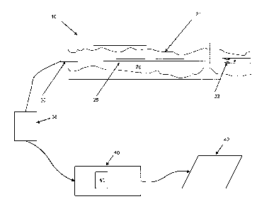
[0018] Figure lA is a generalized schematic of an OCT data collection system
having an imaging probe disposed in a vessel of interest.
[0019] Figure 1B is a flow chart outlining a software-based method to detect
blood
clearing according to an illustrative embodiment of the invention.
[0020] Figure 1C is a longitudinal view of a lumen generated using an OCT
probe
in which the horizontal scale is shown in seconds according to an illustrative
embodiment of the invention.
[0021] Figure 2 is a rectangular (non-polar) representation of a cross-section
of a
lumen generated using data collected using an OCT probe such that certain
LineRadius values are plotted according to an illustrative embodiment of the
invention.
8
CA 02765410 2011-12-13
WO 2011/038048
PCT/US2010/049891
[0022] Figure 3 is the same image as shown in Figure 2 with the addition of a
plotted curve that shows certain smooth radius values as determined using a
method
embodiment of the invention.
[0023] Figure 4 is the same image as shown in Figures 2 and 3 with the
addition of
certain variance values as determined using a method embodiment of the
invention.
DETAILED DESCRIPTION
[0024] Prior to discussing various embodiments of the invention, it is helpful
to
provide an outline of certain features of this application. For example the
use of
headings and sections in the application is not meant to limit the invention;
each
section can apply to any aspect, embodiment, or feature of the invention.
[0025] Throughout the application, where compositions are described as having,
including, or comprising specific components, or where processes are described
as
having, including or comprising specific process steps, it is contemplated
that
compositions of the present teachings also consist essentially of, or consist
of, the
recited components, and that the processes of the present teachings also
consist
essentially of, or consist of, the recited process steps.
[0026] In the application, where an element or component is said to be
included in
and/or selected from a list of recited elements or components, it should be
understood that the element or component can be any one of the recited
elements or
components and can be selected from a group consisting of two or more of the
recited elements or components. Further, it should be understood that elements
and/or features of a composition, an apparatus, or a method described herein
can be
combined in a variety of ways without departing from the spirit and scope of
the
present teachings, whether explicit or implicit herein.
9
CA 02765410 2011-12-13
WO 2011/038048
PCT/US2010/049891
[0027] The use of the terms "include," "includes," "including," "have," "has,"
or
"having" should be generally understood as open-ended and non-limiting unless
specifically stated otherwise.
[0028] The use of the singular herein includes the plural (and vice versa)
unless
specifically stated otherwise. Moreover, the singular forms "a," "an," and
"the"
include plural forms unless the context clearly dictates otherwise. In
addition, where
the use of the term "about" is before a quantitative value, the present
teachings also
include the specific quantitative value itself, unless specifically stated
otherwise. As
used herein, the term "about" refers to a 10% variation from the nominal
value.
[0029] It should be understood that the order of steps or order for performing
certain actions is immaterial so long as the present teachings remain
operable.
Moreover, two or more steps or actions may be conducted simultaneously.
[0030] Where a range or list of values is provided, each intervening value
between
the upper and lower limits of that range or list of values is individually
contemplated
and is encompassed within the invention as if each value were specifically
enumerated herein. In addition, smaller ranges between and including the upper
and
lower limits of a given range are contemplated and encompassed within the
invention. The listing of exemplary values or ranges is not a disclaimer of
other
values or ranges between and including the upper and lower limits of a given
range.
[0031] Figure lA is a high level schematic diagram depicting components of an
OCT system 10. The OCT system 10 can include any suitable light source that
satisfies the coherence and bandwidth requirements of the applications and
data
collection described herein. Figure lA is highly generalized and not to scale.
A
vessel or lumen of interest 20 having a vessel wall 21 is imaged using
catheter 25
CA 02765410 2011-12-13
WO 2011/038048
PCT/US2010/049891
having a catheter portion having an optical fiber-based imaging probe 30
disposed
therein. The catheter 25 includes a flushing subsystem having flush ports 32.
The
flushing system can be of any suitable type or variety that displaces a
sufficient
amount of blood such that in vivo OCT data collection can proceed using the
probe
30. The system 10 includes an OCT system or subsystem 36 that connects to the
imaging probe 30 via an optical fiber. The OCT system or subsystem 36 can
include
a light source such as a laser, an interferometer, various optical paths, a
clock
generator, photodiodes, and other OCT system components.
[0032] A computer or processor can be part of the OCT system 36 or can be
included as a separate subsystem 40 in communication with the OCT system 36.
The computer or processor 40 can include memory, storage, buses and other
components suitable for processing data and executing a flush process or a
software
triggering method for lumen detection and pullback data collection as
discussed
below. In one embodiment, the computer or processor includes software
implementations or programs 41 of the methods described herein that are stored
in
memory and executed using a processor. A display 42 can also be part of the
overall
system 10 for showing cross-sectional scan data as longitudinal scans or in
other
suitable formats.
[0033] One of the fundamental limitations of cardiovascular OCT is that it
cannot
image through blood because the components of red blood cells strongly scatter
the
near-infrared light, making image reconstruction impossible. Therefore, the
lumen
20 must be temporarily cleared of blood for the period that the imaging will
take
place. Displacing the blood via a flush solution such as saline applied
through the
port 32 is possible, but the flush rate must be sufficient to overcome the
native flow,
11
CA 02765410 2011-12-13
WO 2011/038048
PCT/US2010/049891
which in coronary arteries is relatively high, 1- 5 ml per second. In one
embodiment, about 3 to about 5 seconds of clear image time can be established
with
flush-based approaches.
[0034] The amount of clearing time that can be established for a typical bolus
(10 -
20 ml), is dependent on many factors such as the local blood flow rate,
arterial size /
imaging location, prevalence of side-branches, etc. However, it is typically
in the
range of about 2 to about 5 seconds. The amount of time to acquire an OCT
pullback recording (OCT data collection process) is in the range of about 2 to
about
4 seconds. Accordingly, it is desirable that the OCT data acquisition during
the
pullback is initiated the moment sufficient clearing has been established.
[0035] In a preferred embodiment, it is desirable for a computer-based method
to
process the scanned images in substantially real time (or other OCT system
specified
time period suitable for a given application) and trigger the pullback when
sufficient
clearing has been detected. The computer system 40 can execute the methods
described herein. In one embodiment, the methods and system described herein
analyze up to about 150 frames/sec of complex image data in real-time. In
addition,
the embodiments use one or more criterion for determining sufficient clearing.
Further, embodiments of the invention are designed to work in an environment
where the actual lumen shape and size is unknown. Suitable methods of
detecting
the flush clearing on a reliable and real-time basis using an automated
software-
based system or method is one feature of this invention.
[0036] In one embodiment, software detection of lumen or vessel flush clearing
is
initial performed as outlined below such as using all or a subset of the steps
in
Figure 1B. Once a suitable clearing state is achieved the software
automatically
12
CA 02765410 2011-12-13
WO 2011/038048
PCT/US2010/049891
triggers the acquisition of an OCT intravascular pullback data collection
process or
recording. One embodiment of the invention is a software-based method used to
detect the clearing status of the artery. This computer-based method processes
OCT
images of the artery in substantially real time to determine a clearing radius
metric
and quality metric value for each image. When the clearing radius and quality
metric value meet the predefined "clear artery" criteria then the pullback and
data
acquisition starts. In one embodiment, pullback refers to when the probe 30
and/or
catheter 25 is pulled back through a lumen 20 to collect data of the lumen. As
the
probe 30 and /or catheter 25 is pulled back OCT data is collected and sent to
the
OCT system 36 and/or the computer system 40. When the probe 30 is
longitudinally stationary, data is sent to the computer system to execute a
clear state
detection method following initialization of a flush.
[0037] For example, with respect to Figure 1A, if the lumen of interest 20 is
a
coronary artery, OCT imaging of the coronary artery is performed using an OCT
fiber optic imaging catheter such as catheter 25 with probe 30. The OCT
imaging
catheter 25 is placed in the artery at the location where a pullback recording
is to be
started and the OCT software computer-based method flush clearing detection is
initialized (enabled). The operator of the OCT system will then inject a
clearing
medium (flush) such as (saline, contrast solution, dextran or equivalents)
into the
artery to clear it for imaging. The flush clearing detection method executing
on the
computer 40 will then determine when the injected flush has provided
sufficient
clearing in the artery to allow the OCT system to acquire a good image. The
pullback will be triggered by the computer when such a determination has been
made. In one embodiment, the determination of sufficient clearing is made in
real
13
CA 02765410 2011-12-13
WO 2011/038048
PCT/US2010/049891
time by processing each frame as it is acquired by the OCT system 36 or
computer
system 40.
[0038] An exemplary method 50 for flush clearing detection and triggering a
pullback and OCT data collection (and various related steps) is shown in
Figure 1B.
In one embodiment, the flush clearing detection steps of method 50 assume the
following unique characteristics of a clear or unclear artery in an OCT image
in
which the background noise has been removed:
(1) A clear vessel, such as an artery, contains scattering from the artery
wall
and somewhat beyond the wall. Also, the distribution of scattering about the
artery
wall at each angle should be localized near the wall, extending into the
tissue a
characteristic length determined by the physics of OCT imaging (i.e. single-
scattering coherence-gated image reconstruction).
(2) A fully unclear vessel yields a small effective radius due to the presence
of blood around the catheter.
(3) A partially clear vessel has a blood distributed between the catheter and
the vessel wall that reduces the effective radius, and shows significant
distribution of
scattering away from the vessel wall, again determined by the characteristics
of OCT
imaging
[0039] Given these assumptions this computer-based method decides if the
artery
is clear by first determining the value of two metrics, which will be used in
the
decision. These unique image attributes also allow highly efficient
calculations to
be completed where such calculations would not be effective with other imaging
modalities. The first metric, called the radius metric, is the maximum radius
in
micrometers across all angles of the detected clear area of the artery. These
angles
14
CA 02765410 2011-12-13
WO 2011/038048
PCT/US2010/049891
correspond to the 360 degrees of angles that the OCT probe rotates through
while
collecting OCT data. This detected clear area is the detected radius across
all angles
fitted to remove expected minor obstructions (stent, guide-wire, etc.) and
produce a
smoothed contour.
[0040] The second metric, called the quality metric, is an indication of the
quality
of the clearing. It determines the average distribution of scattering about
the
detected clear area divided by the radius value. The unit for this metric is
dimensionless, and as the actual quality of the clearing improves this value
decreases
(a smaller quality metric value means better clearing).
[0041] Once the values of these two metrics have been calculated they are used
to
determine if one of two blood clearing states has been achieved: initial
clearing state
means that some flush clearing has been detected and if full clearing state is
not
detected within a specified timeout then the pullback will be triggered; and
full
clearing state, in one embodiment, means that the artery is sufficiently clear
and
imaging can begin, the pullback will be triggered immediately or after a
specified
delay, if defined. Two parameters are defined as the minimum requirements for
each of these two clearing states: minimum radius is the required minimum
value for
the radius metric; and maximum quality is the required maximum value for the
quality metric. Clearing state and blood clearing state are referred to
interchangeably herein. Thus, a full clearing state and an initial clear state
are both
non-limiting examples of a blood clearing state.
[0042] A third parameter used to determine the current clearing state is
minimum
frames, which specifies the minimum number of consecutive frames that must
meet
CA 02765410 2011-12-13
WO 2011/038048
PCT/US2010/049891
the minimum radius and maximum quality requirements of the clearing state
before
that clearing state has been achieved.
[0043] Figure 1C is a longitudinal view of a lumen generated using an OCT
probe
in which the horizontal scale is shown in seconds according to an illustrative
embodiment of the invention. As shown in the figure, there are five vertical
lines
that were drawn to represent various events that occurred during the recording
or
OCT data collection process. The Li line indicates that the initial clearing
state
(discussed below) is detected approximately 1.4 seconds into the data
collection
process / OCT scan or recording. The L2 line indicates that the full clearing
state
(discussed below) is detected after 2.1 seconds. The L3 line shows when the
pullback was triggered, about 2.5 seconds, which is 0.4 seconds (the trigger
delay)
after the full clearing state was detected. The L3 line is followed
immediately by an
L4 line which indicates when the pullback actually started. An L5 line, at
about 5.3
seconds, indicates where the pullback ended. This Figure 1C provides context
for
the concepts discussed below relating to detecting a blood clearing state in a
lumen
or vessel and triggering one or both of OCT data collection and a pullback
sequence
by which the probe is pulled back through the lumen or vessel.
[0044] As introduced above, Figure 1B is a flow chart outlining, in part, an
exemplary flush clearing detection method 50. As shown in Figure 1B, in one
embodiment, the initial step is to acquire the first or the next frame of OCT
data
(Step 10), such as one or more image data frames. Next, the image data is
prepared
in one embodiment, as outlined below (Step 12). The quality metric and radius
parameters discussed above are also computed (Steps 14 and 16). The next steps
in
16
CA 02765410 2011-12-13
WO 2011/038048
PCT/US2010/049891
the process of Figure 1B include various nested loops and decision trees that
can be
regulated using a software implementation.
[0045] For example as shown in Figure 1B, the frame or collected OCT data is
evaluated to determine whether or not a full clearing state was detected (Step
18). If
the answer is "yes" the next step is to determine if the trigger delay timeout
has
occurred (Step 20). In one embodiment, "trigger delay timeout" occurs when the
trigger delay timer expires. If it has not, the process keeps acquiring frames
and
returns to Step 10. If the trigger delay timeout has occurred, a pullback is
triggered
(Step 21).
[0046] Returning to Step 18, if a full clearing state was not detected, the
process
flow starting with Step 22 commences, such a determination is made if a full
clear
frame is detected or has occurred. In one embodiment, full clear frame is
detected or
occurs when the radius metric for the frame is greater than or equal to the
minimum
radius; and the quality metric for the frame is less than or equal to the
maximum
quality. However, other states for full clear frame can be used in various
embodiments. Similarly, in one embodiment, full clearing state as described
herein
or otherwise defined in a given software embodiment occurs or is signaled when
the
number of consecutive frames that meet the full clear frame criteria is equal
to the
minimum frames.
[0047] With respect to Step 22, if the answer is "yes," than the initial clear
frame
count is incremented (Step 24). Again, in the case where the initial clear
frame
count has been incremented, after such an incrementing step, the next step is
to
determine if the number of full clear frames meets or exceeds the initial
minimum
frames parameter (Step 27). If the condition of Step 27 is satisfied, the step
"full
17
CA 02765410 2011-12-13
WO 2011/038048
PCT/US2010/049891
clearing state is true" and start a trigger delay timer Step 30 is started.
The system
then continues to "acquire the next frame" Step 10. As was the case
previously,
from Step 20 either a pullback will be triggered (Step 21) or an additional
frame will
be acquired (Step 10).
[0048] If a full clear frame is not detected in Step 22, the next step is
evaluate
whether or not an initial clearing state was detected (Step 33). If the answer
is "yes"
indicating that an initial clearing state was detected, the next step is to
determine if
an initial clearing timeout has occurred (Step 35). As discussed below, in one
embodiment, the initial clearing timeout is the period that is started when an
initial
clearing state is detected such that if full clearing is not detected within
that period
then the pullback will be triggered. If this timeout has occurred, the process
flow
continues to Step 21 and a pullback is triggered. In contrast, if during Step
33, no
initial clearing state has been detected, the process 50 continues to
determine if the
frame being evaluated is an initial clear frame (Step 37). If there is no
initial clear
frame, the process returns to Step 10 to evaluate the next frame. However, if
there is
an initial clear frame in Step 37 the next step is to increment the initial
clear frame
count (Step 39). Next, a determination is made as to whether the number of
initial
clear frames is greater than or equal to an initial minimum number of clear
frames
(Step 42). If is not, the process continues with Step 10. Yet, if the initial
number of
clear frames exceeds or meets the threshold number of initial minimum frames
an
initial clearing state is deemed detected. As a result, an initial clearing
timer, which
is longer than the trigger delay timer, is started (Step 45). The process then
continues with Step 10 acquiring the next frame. If the initial clearing
timeout
occurs, when the initial clearing timer expires, pullback is triggered. The
purpose of
18
CA 02765410 2011-12-13
WO 2011/038048
PCT/US2010/049891
this is to assure that pullback will occur even in the event of suboptimal
clearing, as
a backup measure. In one embodiment, during such a situation a pullback can be
triggered is upon the occurrence of the initial clearing timeout when the
initial
clearing timer has expired. Having discussed Figure 1B in some detail, it is
useful
to consider other embodiments relating to OCT data triggering in response to
clearing states in a lumen of interest.
Configuration
[0049] In one embodiment, the methods described herein have several
configurable parameters that may be used to alter the performance of the
methods
described herein to produce results of interest to the operator. Some of these
parameters are referenced in Figure 1B. These include:
Boxcar size, the boxcar depth, in number of frames, to be used to perform
frame averaging of the image data. In one embodiment, the values can include:
1; 2;
4; and 8. However, other values can be used or this feature can be disabled.
Max quality, the maximum quality metric allowed for a clear frame in one
embodiment. This parameter is dimensionless (smaller value indicates better
clearing). Two max quality values are used as input: Init Max Quality, to
describe
the initial clearing or initial clearing state; and max quality, to describe
full clearing
or full clearing state (used interchangeably herein) in one embodiment.
Min radius, the minimum radius metric value allowed for a clear frame in
one embodiment. Value is typically in microns and indicates the minimum radius
outside the catheter radius (described below). In one embodiment, two min
radius
values are used as input: init min radius, to describe the initial clearing;
and min
radius, to describe the full clearing in one embodiment.
19
CA 02765410 2011-12-13
WO 2011/038048
PCT/US2010/049891
Min frames, the minimum number of consecutive frames with a quality
metric value less than max quality and a radius metric greater than min radius
before
the clearing will be triggered in one embodiment. In one embodiment, two min
frames values are used as input: init min frames, used for initial clearing;
and min
frames, used for full clearing.
Initial clearing timeout, the amount of time, in milliseconds or another
temporal unit, after the initial clearing has been detected, that detection of
the full
clearing will continue in one embodiment. If the full clearing is not detected
within
this time period, the pullback will be triggered. See Step 35 of Figure 1B for
an
exemplary application of this timeout.
Trigger delay is the amount of time, in milliseconds or another temporal unit,
which is to elapse after the full clearing state is detected but before the
pullback is
triggered. In one embodiment, the trigger delay setting in the software or
program
embodiment of the method is used to set the trigger delay timeout period.
Initialization
[0050] In one embodiment, when the computer-based method of detecting a
clearing state is initialized the values of the following two parameters are
determined. These are the catheter radius and median value. In one embodiment,
the catheter radius in sample images or data sets is calculated as the
physical
catheter size plus 15%. In one embodiment, no image data closer than this
radius
will be considered for clearing. Thus, a buffer volume that extends around the
catheter itself is ignored when making a determination with respect to
clearing state.
[0051] In addition, the computer determines a background constant or median
value, for the first frame. Typically, the computer generates the median value
by
CA 02765410 2011-12-13
WO 2011/038048
PCT/US2010/049891
generating a histogram of the image data for that frame. In this case, the
median
value will also be the OCT instrument (or system) 'noise floor' in one
embodiment.
The instrument includes the optical system and electronics, the optical
coupler unit
between the optical system and the catheter, and the optical catheter. The
noise
floor includes residual electronic noise, and optical noise created by the non-
coherent light and returned light such as intensity noise and shot noise.
Since the
first frame, by definition, is not cleared, the image near the catheter will
be
dominated by blood scattering. However, the OCT intensity (coherent signal) in
this
case declines rapidly with distance, so that at over about 100 or about 200 um
the
noise floor will be reached. Further, since the scan range is approximately
about 5
mm (5000 um) the median value in this frame will be the noise floor.
Preparation
[0052] As each frame is acquired, the image data for that frame is prepared
for
processing by a flush clearing detection method such as that shown in Figure
1B.
The purpose of this data preparation is to reduce the amount of data and
simplify the
processing procedure because the resolution required to detect a clearing
state is less
than the resolution for imaging. To reduce the amount of data, the image
samples
per line and lines per frame will be reduced. For example, in one embodiment,
if
there are more than 640 samples per line the samples will be reduced by a
factor of
4, otherwise the samples will be reduced by a factor of 2; and the lines per
frame
will be reduced by a factor of 2. Other data processing and extraction of
unnecessary data can be applied as necessary.
[0053] If the boxcar size parameter is greater than 1, then the image data is
included in a running boxcar average. The boxcar size is used as the frame
depth of
21
CA 02765410 2011-12-13
WO 2011/038048
PCT/US2010/049891
the averaging, new frames are added to the averaging, and as the number of
frames
included in the average exceeds the frame depth the oldest frames are
subtracted.
This averaging is performed on a sample by sample basis in one embodiment.
[0054] For one embodiment of a method for detecting a clearing state and/or
triggering on the same, four distinct scattering sources are assumed: red
blood cells,
"clear liquid", stent strut and artery wall. The stent strut is assumed to be
either near
the artery wall, or will subtend a very small angle or both.
[0055] Ideally, for clearing a vessel, "clear liquid", stent strut and artery
wall will
be the only scattering factors. The scattering intensity for "clear liquid" is
the
median value for frame 1, which is the instrument noise floor as determined
above.
This value can be subtracted from all subsequent frames to compensate for
background. This results in an Intensity value for each sample:
Intensity max (0, Sample ¨Median)
[0056] In one embodiment, image data inside the catheter radius is ignored or
zeroed out as the Intensity is calculated. In a cleared frame, scattering from
the
artery wall and somewhat beyond the wall should be viewable. By measuring the
radius to the vessel wall as a function of angle, it should form a fairly
smooth curve.
Additionally, for a cleared artery, the distribution of scatter about the
vessel wall
radius at each angle should be fairly small. For a fully uncleared vessel,
there are
red blood cells very close to the fiber, yielding a small effective radius.
For a partly
cleared vessel, there are red blood cells distributed between the fiber and
the vessel
wall, reducing the effective radius a bit, but showing significant
distribution of
scattering away from the artery wall. As a result, the software-based method
22
CA 02765410 2011-12-13
WO 2011/038048
PCT/US2010/049891
computes two metrics for the image, the effective artery radius metric, and
the
clearing quality metric.
Compute Radius Metric
[0057] Figure 2 is a rectangular (non-polar) representation of an OCT image
with
that shows the LineRadius (or line radius) values as calculated in the first
step of the
compute radius metric process. In one embodiment, the first step is computing
a
LineRadius for each rotation angle of the probe within a frame. As an example,
certain line radius values are plotted according to an illustrative embodiment
of the
invention in Figure 2. In one embodiment, to compute each LineRadius value,
the
intensity centroid of each line is calculated as follows (where cr is the
catheter radius
and n is the number of reduced samples per line, and i is the line number, i
ranging
from 1 to m):
L=" = Intens* (lc ¨ cr)
kcr -
LineRadius
L
k=cr Intensity
[0058] Thus, the use of a LineRadius value provides a method for calculating a
close approximation for actual physical radius of a vessel, and depends on (as
mentioned previously) the unique characteristics of the OCT signal. Here the
signal
intensity, in the cleared vessel, is highly localized near the vessel wall due
to the
rapid attenuation of the OCT signal with distance into tissue. The position of
the
centroid of this signal (the 'LineRadius') will occur a small distance inside
the
vessel wall, not exactly on the vessel surface. Conventional edge finding
techniques
would localize the radius on the physical surface but come at the expense of
much
more computationally intensive process. Thus, the use of intensity as a proxy
or
23
CA 02765410 2011-12-13
WO 2011/038048
PCT/US2010/049891
surrogate for a physical radius dramatically improves the OCT system's ability
to
quickly determine a lumen radius or cross-sectional shape. Various intensity
distribution moments can be compared to determine parameters of interest such
as
position and quality metrics.
[0059] Hence, this LineRadius value is computationally efficient (one
multiplication and two running sums), but does not attempt to localize the
actual
lumen boundary with high precision at the vessel surface. Thus, it is not
suitable for
accurately measuring a conventional lumen diameter, but provides an excellent
estimate of the cleared area. Another innovative step is to calculate a smooth
fitting
of the LineRadii using a fairly low-order harmonic series (shown below).
P
.1 r= LineRadius ¨(Bn+L (AA' sin(2Trr ))+
( B 2Trr cos( ))))2
u =1
M
J is minimized over the A and B parameters, m is the number of lines per image
frame (each image frame representing 360 degrees of catheter rotation), A and
B are
the weighting coefficients, and p is the harmonic order, typically 3 or less.
The sine
and cosine functions are used since, for a catheter off-center in an assumed
round
artery, the distance from the catheter center to the lumen edge as a function
of
rotation angle will follow a sinusoidal function. In one embodiment, the order
of the
curve fitting series J or the series of sine and cosine functions defined
therein is 5 or
less. This data smoothing process efficiently removes artifacts unique to the
OCT
intravascular image, such as the shadow caused by a guidewire using in the OCT
system.
The smoothed radius profile as a function of angle is then:
24
CA 02765410 2011-12-13
WO 2011/038048
PCT/US2010/049891
Tr r
SmoothRadius B + r =1 (Ar sin(2 i ))+(B, cos(2Trri))
The effective clearing radius metric is the maximum of the SmoothRadii across
all
lines of the frame. This value is in samples, and represents the maximum
radius of
the clearing in samples outside the catheter. Examples of smooth radii values
are
shown in Figure 3. Figure 3 is the same image as shown in Figure 2 with the
addition of a plotted curve that shows certain smooth radius values SR as
determined
using the approach provided herein.
Compute Quality
[0060] Next, it is useful to consider the distribution of scattering about the
vessel
wall such as an artery wall as determined by the computer system. To do this,
the
software calculates a Variance, or distribution of scattering about the smooth
radius,
for each line of the frame as shown in Figure 4. This is calculated as a mean-
squared
distribution for each line, as follows:
k-cr Intensity ,,k((k ¨cr)¨ SmoothRadius,)2
Variance
Intensity
k-er 1,k
[0061] If the intensity (signal) is localized very close to the smooth radius,
the
variance term will be small. A plot of variance values V is shown in Figure 4.
The
quality metric can be calculated using the variance and the effective artery
radius
metric as follows:
Quality=-V mean(Variance)
Radius
CA 02765410 2011-12-13
WO 2011/038048 PCT/US2010/049891
The unit for the quality metric (alternatively referred to as Quality) is
dimensionless,
and as the quality of the clearing in the image improves the value of this
metric will
decrease (lower quality metric value means better clearing). This simple
variable
again allows computationally efficient distinction of no clear, partial clear
and fully
clear situations as shown in the table below by amplifying the differences
between
distinguishing characteristics of the OCT images:
Physical Condition Variance LineRadius Quality Metric
No clearing ¨ Low Very Low High (poor image)
blood field
Partial Clearing High Moderate Moderate-high
Full Clear Low Large Low
Determine C1earin2 State
[0062] In one embodiment, there are two possible clearing states to be tested
for
once the Radius and Quality metric values have been calculated, the full
clearing
and the initial clearing states. In one embodiment, a single blood clear state
is
sufficient. When determining the clearing state for the current frame, the
software
resident in memory in the computer system connected to the probe detects if
the
image is in the full clearing state. This blood clearing state indicates that
sufficient
clearing has been detected in the image so that imaging of the artery or other
vessel
can begin. If the radius metric value for this frame is greater than the min
radius
setting, and the quality value is less than the max quality lower bound
setting, then
this frame is determined to be "fully clear." However, the full clearing state
is not
26
CA 02765410 2011-12-13
WO 2011/038048
PCT/US2010/049891
detected until the number of "fully clear" frames equals or exceeds the min
frames
setting. When all of these criteria have been met, the pullback will be
triggered.
[0063] The second state, initial clearing, indicates that some amount of
clearing
has been detected in the image. If the radius metric value for this frame is
greater
than the init min radius setting, and the quality metric value is less than
the initial
max quality lower bound setting (> full clear lower bound), then this frame is
"initially clear". However, the initial clearing state is not detected until
the number
of consecutive "initially clear" frames equals the init min frames setting.
When
initial clearing is detected the initial clearing timeout period is started,
and if full
clearing is not detected within that period then the pullback will be
triggered.
Clinical Implementation
[0064] The above computer-based method is computationally efficient and
effective at determining when scattering blood has been removed from an artery
whose size, relative position to the imaging core of the catheter and relative
shape
are all unknown prior to clearing.
[0065] In one clinical implementation, another factor may be considered.
Specifically, it is desirable to inject small boluses of saline or radio-
opaque contrast
agent (contrast' or 'dye') during the course of the OCT data collection
process.
These dye shots typically range from about 5 ml to at most about 20 ml. The
contrast agent shows the outline of the vessels in the fluoroscopic (x-ray)
image to
the interventional cardiologist or other OCT operator and is invaluable in
guiding
therapy (stent deployment, catheter location, etc.). Since contrast agent is
optically
clear, it is an effective flush agent. Thus, the OCT system must guard against
these
27
CA 02765410 2011-12-13
WO 2011/038048
PCT/US2010/049891
small dye shots producing false triggers as the bolus size is too small to
produce a
complete pullback OCT image of the vessel.
[0066] Accordingly, in one embodiment, the computer-based method is only
'armed' for triggering when either the system is enabled, signifying the next
clearing
event will be due to a bolus sized for OCT imaging, or by communication with
an
automated injector pump which has several injection sequences pre-programmed
(e.g. 'dye shot' and 'OCT image data collection'). When an OCT image data
collection injection is selected, the pump can communicate this to the OCT
system,
thereby arming the flush clearing detection methods and triggering methods.
This
communication can occur via several mechanisms, such as standard serial
communication lines. Many modern injector pumps have this capability already
existing as they facilitate a similar communication to the x-ray system.
[0067] Furthermore, through this communication set-up, clinical efficiency and
patient safety can be enhanced. For example, it is desirable to limit exposure
both to
ionizing x-ray radiation (cell damage or mutation leading to cancer risk) and
excessive contrast media as the radio-opaque material (typically iodine) is
toxic in
large quantities and is linked to renal insufficiency or outright renal
failure. Hence
by using a contrast agent as the flush agent, and synchronizing both the OCT
image
and the x-ray equipment, OCT and fluoroscopic images can be created
simultaneously, neither degrading nor affecting the other. Contrast agent, due
to its
viscosity, allows smaller boluses and much lower flush rates than the volume
for
flushing with low-viscosity saline would require. As a result, using contrast
agent as
the flush offers additional patient safety advantages, as the high flush rates
required
by saline usage can be damaging to arterial walls. The computer-based method
28
CA 02765410 2011-12-13
WO 2011/038048
PCT/US2010/049891
above is unaffected by the type of flush media used, as long as it is
sufficiently
optically clear at the OCT wavelength being used. In on embodiment, sufficient
clearing occurs when the hematocrit level is reduced to the point that OCT
images of
sufficient quality for the intended clinical purpose can be made.
[0068] An alternative to the communication with the pump, especially if a
manual
(syringe) injection of flush media is used, is the use of a sterile pressure
sensor in-
line with the flush delivery mechanism. For example, a commercial disposable
blood pressure transducer could be attached directly to the syringe used for
flushing.
The signal, from the transducer, would be detected similarly to the signal
from the
automated pump. Either signal can be used to control the OCT recording in one
of
two basic ways.
[0069] In the first way, smallest recording size, all image recording and
pullback
occurs simultaneously with the advent of a positive clearing signal from the
computer-based method. In the second way, which produces a ¨25% longer
recording, the image recording starts when a flush signal is received (from
either the
pump or the transducer), but the pullback commences when the positive clearing
signal is received. The resulting recording will indicate the stationary part
of the
scan and the portion during which pullback occurred. The advantage of the
second
method is that the recording captures the actual clearing and can be used to
further
refine the computer-based method.
Non-limiting Software Features and Embodiments for Implementing OCT Methods
and Systems
[0070] The present invention may be embodied in many different forms,
including, but in no way limited to, computer program logic for use with a
processor
29
CA 02765410 2011-12-13
WO 2011/038048
PCT/US2010/049891
(e.g., a microprocessor, microcontroller, digital signal processor, or general
purpose
computer), programmable logic for use with a programmable logic device, (e.g.,
a
Field Programmable Gate Array (FPGA) or other PLD), discrete components,
integrated circuitry (e.g., an Application Specific Integrated Circuit
(ASIC)), or any
other means including any combination thereof In a typical embodiment of the
present invention, some or all of the processing of the data collected using
an OCT
probe and the processor-based system is implemented as a set of computer
program
instructions that is converted into a computer executable form, stored as such
in a
computer readable medium, and executed by a microprocessor under the control
of
an operating system. Thus, query response and input data are transformed into
processor understandable instructions suitable for generating OCT data,
triggering
on a blood clearing state, using intensity to determine lumen geometry,
histology
images, OCT images, triggers, flush monitoring, signal processing , signal to
noise
evaluation in images, image comparison, signal processing, artifact removal,
and
other features and embodiments described above.
[0071] Computer program logic implementing all or part of the functionality
previously described herein may be embodied in various forms, including, but
in no
way limited to, a source code form, a computer executable form, and various
intermediate forms (e.g., forms generated by an assembler, compiler, linker,
or
locator). Source code may include a series of computer program instructions
implemented in any of various programming languages (e.g., an object code, an
assembly language, or a high-level language such as Fortran, C, C++, JAVA, or
HTML) for use with various operating systems or operating environments. The
source code may define and use various data structures and communication
CA 02765410 2011-12-13
WO 2011/038048
PCT/US2010/049891
messages. The source code may be in a computer executable form (e.g., via an
interpreter), or the source code may be converted (e.g., via a translator,
assembler, or
compiler) into a computer executable form.
[0072] The computer program may be fixed in any form (e.g., source code form,
computer executable form, or an intermediate form) either permanently or
transitorily in a tangible storage medium, such as a semiconductor memory
device
(e.g., a RAM, ROM, PROM, EEPROM, or Flash-Programmable RAM), a magnetic
memory device (e.g., a diskette or fixed disk), an optical memory device
(e.g., a CD-
ROM), a PC card (e.g., PCMCIA card), or other memory device. The computer
program may be fixed in any form in a signal that is transmittable to a
computer
using any of various communication technologies, including, but in no way
limited
to, analog technologies, digital technologies, optical technologies, wireless
technologies (e.g., Bluetooth), networking technologies, and internetworking
technologies. The computer program may be distributed in any form as a
removable
storage medium with accompanying printed or electronic documentation (e.g.,
shrink-wrapped software), preloaded with a computer system (e.g., on system
ROM
or fixed disk), or distributed from a server or electronic bulletin board over
the
communication system (e.g., the Internet or World Wide Web).
[0073] Hardware logic (including programmable logic for use with a
programmable logic device) implementing all or part of the functionality
previously
described herein may be designed using traditional manual methods, or may be
designed, captured, simulated, or documented electronically using various
tools,
such as Computer Aided Design (CAD), a hardware description language (e.g.,
31
CA 02765410 2011-12-13
WO 2011/038048
PCT/US2010/049891
VHDL or AHDL), or a PLD programming language (e.g., PALASM, ABEL, or
CUPL).
[0074] Programmable logic may be fixed either permanently or transitorily in a
tangible storage medium, such as a semiconductor memory device (e.g., a RAM,
ROM, PROM, EEPROM, or Flash-Programmable RAM), a magnetic memory
device (e.g., a diskette or fixed disk), an optical memory device (e.g., a CD-
ROM),
or other memory device. The programmable logic may be fixed in a signal that
is
transmittable to a computer using any of various communication technologies,
including, but in no way limited to, analog technologies, digital
technologies, optical
technologies, wireless technologies (e.g., Bluetooth), networking
technologies, and
internetworking technologies. The programmable logic may be distributed as a
removable storage medium with accompanying printed or electronic documentation
(e.g., shrink-wrapped software), preloaded with a computer system (e.g., on
system
ROM or fixed disk), or distributed from a server or electronic bulletin board
over the
communication system (e.g., the Internet or World Wide Web).
[0075] Various examples of suitable processing modules are discussed below in
more detail. As used herein a module refers to software, hardware, or firmware
suitable for performing a specific data processing or data transmission task.
Typically, in a preferred embodiment a module refers to a software routine,
program, or other memory resident application suitable for receiving,
transforming,
routing and processing instructions, or various types of data such as OCT scan
data,
interferometer signal data, clock signals, region of interest types, formulas,
and other
information of interest.
32
CA 02765410 2011-12-13
WO 2011/038048
PCT/US2010/049891
[0076] Computers and computer systems described herein may include operatively
associated computer-readable media such as memory for storing software
applications used in obtaining, processing, storing and/or communicating data.
It
can be appreciated that such memory can be internal, external, remote or local
with
respect to its operatively associated computer or computer system.
[0077] Memory may also include any means for storing software or other
instructions including, for example and without limitation, a hard disk, an
optical
disk, floppy disk, DVD (digital versatile disc), CD (compact disc), memory
stick,
flash memory, ROM (read only memory), RAM (random access memory), DRAM
(dynamic random access memory), PROM (programmable ROM), EEPROM
(extended erasable PROM), and/or other like computer-readable media.
[0078] In general, computer-readable memory media applied in association with
embodiments of the invention described herein may include any memory medium
capable of storing instructions executed by a programmable apparatus. Where
applicable, method steps described herein may be embodied or executed as
instructions stored on a computer-readable memory medium or memory media.
These instructions may be software embodied in various programming languages
such as C++, C, Java, and/or a variety of other kinds of software programming
languages that may be applied to create instructions in accordance with
embodiments of the invention.
[0079] It is to be understood that the figures and descriptions of the
invention have
been simplified to illustrate elements that are relevant for a clear
understanding of
the invention, while eliminating, for purposes of clarity, other elements.
Those of
ordinary skill in the art will recognize, however, that these and other
elements may
33
CA 02765410 2011-12-13
WO 2011/038048
PCT/US2010/049891
be desirable. However, because such elements are well known in the art, and
because they do not facilitate a better understanding of the invention, a
discussion of
such elements is not provided herein. It should be appreciated that the
figures are
presented for illustrative purposes and not as construction drawings. Omitted
details
and modifications or alternative embodiments are within the purview of persons
of
ordinary skill in the art.
[0080] It can be appreciated that, in certain aspects of the invention, a
single
component may be replaced by multiple components, and multiple components may
be replaced by a single component, to provide an element or structure or to
perform
a given function or functions. Except where such substitution would not be
operative to practice certain embodiments of the invention, such substitution
is
considered within the scope of the invention.
[0081] The examples presented herein are intended to illustrate potential and
specific implementations of the invention. It can be appreciated that the
examples
are intended primarily for purposes of illustration of the invention for those
skilled
in the art. There may be variations to these diagrams or the operations
described
herein without departing from the spirit of the invention. For instance, in
certain
cases, method steps or operations may be performed or executed in differing
order,
or operations may be added, deleted or modified.
[0082] Furthermore, whereas particular embodiments of the invention have been
described herein for the purpose of illustrating the invention and not for the
purpose
of limiting the same, it will be appreciated by those of ordinary skill in the
art that
numerous variations of the details, materials and arrangement of elements,
steps,
34
CA 02765410 2014-01-14
structures, and/or parts may be made within the principle and scope of the
invention.
4676919.1