Note: Descriptions are shown in the official language in which they were submitted.
CA 02765437 2012-01-23
TEST MODE SUPPORT FOR METERING ACCURACY TESTS
CROSS REFERENCE TO RELATED APPLICATIONS
100011 This application claims the benefit of U.S. Provisional Patent
Application
Serial No. 61/435,483, filed January 24, 2011, the contents of which are
hereby
incorporated by reference in their entirety.
BACKGROUND
[00021 Utilities may use communication systems to read data from electricity,
water, and/or gas meters. These communication systems and meters may be
installed at
customer locations and used to measure consumption and other parameters to
determine a
customer's monthly bill.
[00031 Historically, these metering devices are installed in the field and
they are
left in the field for the life of the meter, typically 15-25 years. With the
growth of
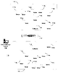
communication systems and smart meters, functionality may be downloaded to the
meters
via remote firmware upgrades. With this capability, utilities may setup a test
system
where new firmware functionality may be tested and verified before being
deployed to a
production system used for billing purposes. This has forced utilities to
order different
sets of equipment, one set with a network identifier for the production system
and one or
more sets with a network identifier for a test system or systems.
[00041 Utilities have also historically performed metering accuracy tests on
the
various quantities that can be measured by an electricity meter. With the
proliferation of
radio communications, the radio frequency energy generated from the
communication
module may have undesired influence on other circuitry in the electricity
meter.
SUMMARY OF THE INVENTION
100051 Various techniques for supporting metering accuracy tests are disclosed
herein, including a method for programming a communication device, configured
to
operate in a metering network, from an active utility identifier to a
production utility
-1-
CA 02765437 2012-01-23
identifier or a test utility identifier, and a method for evaluating an impact
of radio modes
while performing a metering accuracy test on a communication device. Systems
and
apparatuses for carrying out these methods are also disclosed.
100061 Exemplary embodiments are directed to methods and devices for
communicating in a metering network. A metering communication device may
receive an
active (e.g., present) utility identifier of the metering communication device
that
corresponds to a metering network. For example, the active utility identifier
may
correspond to a production network or a test network. In an embodiment, the
active utility
identifier of the metering communication device is changed to a received valid
utility
identifier associated with the metering communication device. The received
valid utility
identifier may be one of one or more valid utility identifiers that enable the
metering
communication device to communicate on another metering network. For example,
the
metering communication device may communicate with other devices having the
valid
utility identifier, and the valid utility identifier may correspond to another
metering
network, such as a production network or a test network. Embodiments also may
operate
the metering communication device in one or more radio test modes while
performing one
or more metering accuracy tests on the metering communication device.
100071 An exemplary embodiment is directed to a metering communication
device. The metering communication device comprises a transceiver configured
to
transmit an active utility identifier to a plurality of metering networks. For
example, the
transceiver may transmit radio signals in a production network and/or a test
network. The
metering communication device may further comprise a processor and a memory.
The
processor may be in electrical communication with the transceiver and the
memory. The
memory may be configured to store an active utility identifier and a utility
configuration
table. The active utility identifier may be used for communicating in an
active metering
network of the plurality of metering networks. The utility configuration table
may include
one or more valid utility identifiers for communicating in other metering
networks. The
processor may be configured to change the active utility identifier of the
metering
communication device to a valid utility identifier of the one or more valid
utility identifiers
associated with the metering device. The changed active utility identifier may
enable the
metering communication device to communicate with another metering network in
the
plurality of metering networks. The transceiver may be further configured to
operate in
-2-
CA 02765437 2012-01-23
one or more radio test modes. While the transceiver operates in the one or
more radio test
modes, the processor may be further configured to perform one or more metering
accuracy
tests on the metering communication device.
[0008] According to another embodiment, a computer-readable storage medium
is disclosed. The computer-readable storage medium may store computer-
executable
instructions for performing steps in a method. The method may comprise
receiving an
active utility identifier of the metering communication device. The active
utility identifier
may correspond to a metering network. The metering communication device may
communicate with one or more devices on the metering network having the active
utility
identifier. One or more valid utility identifiers associated with the metering
communication device may be received. The one or more valid utility
identifiers may
enable the metering communication device to communicate on another metering
network.
The computer-executable instructions may change the active utility identifier
of the
metering communication device to a valid utility identifier. The metering
communication
device, using the changed active utility identifier, may communicate with one
or more
devices on the other meting network having the valid utility identifier.
100091 Various embodiments may realize certain advantages. For example,
changing a utility identifier of a metering communication device may allow the
metering
communication device to operate in a production network and/or a test network.
Additionally, embodiments may allow a metering communication device to operate
in a
radio test mode while performing metering accuracy tests. Accordingly,
embodiments
may have increased flexibility and efficiency.
[0010] Other features and advantages of the described embodiments may become
apparent from the following detailed description and accompanying drawings.
BRIEF DESCRIPTION OF THE DRAWINGS
[0011] The foregoing summary, as well as the following detailed description,
is
better understood when read in conjunction with the appended drawings.
Exemplary
embodiments further described herein are illustrated in Figures 1-4. However,
it will be
understood that the invention is not limited to the specific embodiments
disclosed. In the
drawings:
-3-
CA 02765437 2012-01-23
100121 Figure 1 is a diagram of an exemplary metering communication system
employing wireless networking;
[00131 Figure 2 expands upon the diagram of Figure 1 and illustrates the
exemplary metering communication system in greater detail;
100141 Figure 3A is a block diagram illustrating an exemplary gatekeeper (also
referred to as a "collector") of the metering communication system of Figure
1;
[00151 Figure 3B is a block diagram illustrating an exemplary metering device
of
the metering communication system of Figure 1;
[00161 Figure 3C illustrates one embodiment of an outbound data packet format
of the metering communication system illustrated in Figures 1, 2, 3A and 3B,
and Figure
3D illustrates one embodiment of an inbound data packet format; and
[0017] Figure 4 is a process flow diagram illustrating an example method for
programming and operating a metering communication device according to an
embodiment.
DETAILED DESCRIPTION
[00181 Exemplary embodiments of systems, methods and apparatus for enabling
metering communication devices to be used for test purposes and/or productions
purposes
are provided herein. It will be understood that the invention is not limited
to the specific
embodiments described herein. While certain details have been provided to
illustrate the
embodiments described herein, it is understood that the invention may be
practiced
without those specific details. Acronyms and other terms may be used in the
following
description, however they are not intended to limit the scope of the invention
as defined by
the appended claims.
-4-
CA 02765437 2012-01-23
100191 The systems, methods and apparatus described herein enable
communication devices in a utility system to support metering accuracy tests.
For
example, a utility may change a network identifier from an active utility
identifier to a
production utility identifier or a test utility identifier. According to
another example, an
impact of radio modes may be evaluated while performing one or more metering
accuracy
tests on a communication device.
[00201 One example of a metering communication system 110 in which the
systems, methods, and apparatus described herein may be employed is
illustrated in
Figures 1, 2, and 3A-D. The description given herein with respect to those
figures is for
exemplary purposes only and is not intended in any way to limit the scope of
potential
embodiments.
[00211 System 110 comprises a plurality of metering communication devices, or
"meters" 114, which may be operable to sense and record consumption or usage
of a
service or commodity such as, for example, electricity, water, and/or gas.
Meters 114 may
be located at customer premises such as, for example, a home or place of
business. Meters
114 may comprise circuitry for measuring the consumption of the service or
commodity
being consumed at their respective locations and for generating data
reflecting the
consumption, as well as other data related thereto. Meters 114 may also
comprise circuitry
for wirelessly transmitting data generated by the meter to a remote location.
Meters 114
may further comprise circuitry for receiving data, commands or instructions
wirelessly.
Meters that are operable to both receive and transmit data may be referred to
as "bi-
directional" or "two-way" meters (or nodes), while meters that are only
capable of
transmitting data may be referred to as "transmit-only" or "one-way" meters.
In bi-
directional meters, the circuitry for transmitting and receiving may comprise
a transceiver.
In an illustrative embodiment, meters 114 may be, for example, electricity
meters
manufactured by Elster Solutions, LLC and marketed under the trade name REX.
[00221 System 110 further comprises collectors 116. In one embodiment,
collectors 116 are also meters operable to detect and record usage of a
service or
commodity such as, for example, electricity, water, and/or gas. In addition,
collectors 116
may be operable to send data to and receive data from meters 114. Thus, like
the meters
114, the collectors 116 may comprise both circuitry for measuring the
consumption of a
service or commodity and for generating data reflecting the consumption and
circuitry for
-5-
CA 02765437 2012-01-23
transmitting and receiving data. In one embodiment, collector 116 and meters
114 may
communicate with and amongst one another using any one of several wireless
techniques
such as, for example, frequency hopping spread spectrum (FHSS) and/or direct
sequence
spread spectrum (DSSS). Collectors 116 are also sometimes referred to as
"gatekeepers."
[00231 A collector 116 and the meters 114 with which it communicates may
define a subnet or local area network (LAN) 120 of system 110. In one
embodiment, each
subnet or LAN may define a controlled, wireless mesh network with the
collector 116
(gatekeeper) of that LAN effectively controlling the mesh network. Further
details of how
such a LAN is initialized, defined and maintained are described hereinafter.
100241 As used herein, a collector 116 and the meters 114 with which it
communicates may be referred to as "nodes" in the subnet/LAN 120. In each
subnet/LAN
120, each meter transmits data related to consumption of the commodity being
metered at
the meter's location. The collector 116 may receive the data transmitted by
each meter
114, effectively "collecting" it, and then periodically transmits the data
from the meters in
the subnet/LAN 120 to a data collection server 206. The data collection server
206 stores
the data for analysis and preparation of bills, for example. The data
collection server 206
may be a specially programmed general purpose computing system and may
communicate
with collectors 116 via a network 112. The network 112 may comprise any form
of
network, including a wireless network or a fixed-wire network, such as a local
area
network (LAN), a wide area network (WAN), the Internet, an intranet, a
telephone
network, such as the public switched telephone network (PSTN), a Frequency
Hopping
Spread Spectrum (FHSS) radio network, a mesh network, a Wi-Fi (802.11)
network, a Wi-
Max (802.16) network, a land line (POTS) network, a TCP/IP network, a W-WAN, a
GPRS network, a CDMA network, a Fiber network, or any combination of the
above.
100251 Referring now to Figure 2, further details of the metering
communication
system 110 are shown. Typically, the system will be operated by a utility
company or a
company providing information technology services to a utility company. In
Figure 2,
some or all of the components illustrated in dashed-box 200 may be referred to
a utility's
"operations center," "head-end," or similar name. As shown, the operations
center 200
may comprise a network management server 202, a network management system
(NMS)
204 and the data collection server 206 that together manage one or more
subnets/LANs
120 and their constituent nodes. The NMS 204 tracks changes in network state,
such as
-6-
CA 02765437 2012-01-23
new nodes registering/unregistering with the system 110, node communication
paths
changing, etc. This information is collected for each subnet/LAN 120 and is
detected and
forwarded to the network management server 202 and data collection server 206.
[0026] Each of the meters 114 and collectors 116 is assigned an identifier
(LAN
ID) that uniquely identifies that meter or collector on its subnet/LAN 120. In
this
embodiment, communication between nodes (e.g., the collectors and meters) and
the
communication system 110 is accomplished using the LAN ID. However, it is
preferable
for operators of a utility to query and communicate with the nodes using their
own
identifiers. To this end, a marriage file 208 may be used to correlate a
utility's identifier
for a node (e.g., a utility serial number) with both a manufacturer serial
number (e.g., a
serial number assigned by the manufacturer of the meter) and the LAN ID for
each node in
the subnet/LAN 120. In this manner, the utility may refer to the meters and
collectors by
the utility's identifier, while the system may employ the LAN ID for the
purpose of
designating particular meters during system communications.
[0027] A device configuration database 210 stores configuration information
regarding the nodes. For example, in the metering communication system 110,
the device
configuration database may include data regarding time of use (TOU)
switchpoints, etc.
for the meters 114 and collectors 116 communicating in the system 110. A data
collection
requirements database 212 includes information regarding the data to be
collected on a per
node basis. For example, a utility may specify that metering data such as load
profile,
demand, TOU, etc. is to be collected from particular meter(s) I 14a. Reports
214 including
information on the network configuration may be automatically generated or in
accordance
with a utility request.
[0028] The network management system (NMS) 204 may maintain a database
describing the current state of the global fixed network system (current
network state 226)
and a database describing the historical state of the system (historical
network state 222).
The current network state 226 contains data regarding current meter-to-
collector
assignments, etc. for each subnet/LAN 120. The historical network state 222 is
a database
from which the state of the network at a particular point in the past may be
reconstructed.
The NMS 204 is responsible for, amongst other things, providing reports 214
about the
state of the network. The NMS 204 may be accessed via an API 220 that is
exposed to a
user interface 216 and a Customer Information System (CIS) 218. Other external
-7-
CA 02765437 2012-01-23
interfaces may also be implemented. In addition, the data collection
requirements stored
in the database 212 may be set via the user interface 216 or CIS 218.
100291 The data collection server 206 may collect data from the nodes (e.g.,
collectors 116) and store the data in a database 224. The data may include
metering
information, such as energy consumption, and may be used for billing purposes,
etc. by a
utility provider.
100301 The network management server 202, network management system 204
and data collection server 206 communicate with the nodes in each subnet/LAN
120 via
network 112.
[00311 Figure 3A is a block diagram illustrating further details of one
embodiment of a collector 116. Although certain components are designated and
discussed with reference to Figure 3A, it should be appreciated that such
designations and
discussion are not limiting. In fact, various other components typically found
in an
electronic meter may be a part of collector 116, but have not been shown in
Figure 3A for
the purposes of clarity and brevity. Also, other components may be used to
accomplish
the operation of collector 116. The components that are shown and the
functionality
described for collector 116 are provided as examples, and are not meant to be
exclusive of
other components or other functionality.
[00321 As shown in Figure 3A, collector 116 may comprise metering circuitry
304 that performs measurement of consumption of a service or commodity and a
processor
305 that controls the overall operation of the metering functions of the
collector 116. The
collector 116 may further comprise a display 310 for displaying information
such as
measured quantities and meter status and a memory 312 for storing data. The
collector
116 further comprises wireless LAN communications circuitry 306 for
communicating
wirelessly with the meters 114 in a subnet/LAN and a network interface 308 for
communication over the network 112.
[00331 In an embodiment, the metering circuitry 304, processor 305, display
310
and memory 312 may be implemented using an A3 ALPHA meter available from
Elster
Solutions, LLC. In that embodiment, the wireless LAN communications circuitry
306
may be implemented by a LAN Option Board (e.g., a 900 MHz two-way radio)
installed
within the A3 ALPHA meter, and the network interface 308 may be implemented by
a
WAN Option Board (e.g., a telephone modem) also installed within the A3 ALPHA
meter.
-8-
CA 02765437 2012-01-23
In this embodiment, the WAN Option Board 308 may route messages from network
112
(via interface port 302) to either the meter processor 305 or the LAN Option
Board 306.
LAN Option Board 306 may use a transceiver (not shown), for example a 900 MHz
radio,
to communicate data to meters 114. Also, LAN Option Board 306 may have
sufficient
memory to store data received from meters 114. This data may include, but is
not limited
to the following: current billing data (e.g., the present values stored and
displayed by
meters 114), previous billing period data, previous season data, and load
profile data.
100341 LAN Option Board 306 may be capable of synchronizing it's time to a
real
time clock (not shown) in A3 ALPHA meter, thereby synchronizing the LAN
reference
time to the time in the meter. The processing necessary to carry out the
communication
functionality and the collection and storage of metering data of the collector
116 may be
handled by the processor 305 and/or additional processors (not shown) in the
LAN Option
Board 306 and/or the WAN Option Board 308.
[00351 The responsibility of a collector 116 is wide and varied. Generally,
collector 116 may be responsible for managing, processing and routing data
communicated between the collector and network 112 and between the collector
and
meters 114. Collector 116 may continually or intermittently read the current
data from
meters 114 and store the data in a database (not shown) in collector 116. Such
current data
may include but is not limited to the total kWh usage, the Time-Of-Use (TOU)
kWh
usage, peak kW demand, and other energy consumption measurements and status
information. Collector 116 also may read and store previous billing and
previous season
data from meters 114 and store the data in the database in collector 116. The
database
may be implemented as one or more tables of data within the collector 116.
100361 In an embodiment, the LAN Option Board 306 may employ a CC 1110
chip available from Texas Instruments Incorporated to implement its wireless
transceiver
functionality. The CCII10 chip has a built-in Received Signal Strength
Indication (RSSI)
capability that provides a measurement of the power present in a received
radio signal.
100371 Figure 3B is a block diagram of an exemplary embodiment of a meter 114
that may operate in the system 110 of Figures 1 and 2. As shown, the meter 114
comprises metering circuitry 304' for measuring the amount of a service or
commodity
that is consumed, a processor 305' that controls the overall functions of the
meter, a
display 310' for displaying meter data and status information, and a memory
312' for
-9-
CA 02765437 2012-01-23
storing data and program instructions. The meter 114 further comprises
wireless
communications circuitry 306', such as a transceiver, for transmitting and
receiving data
to/from other meters 114 or a collector 116. The wireless communication
circuitry 306'
may comprise, for example, the aforementioned CC 1110 chip available from
Texas
Instruments Incorporated .
[0038] Referring again to Figure 1, in an embodiment, a collector 116 directly
communicates with a subset of the plurality of meters 114 in its particular
subnet/LAN.
Meters 114 with which collector 116 directly communicates may be referred to
as "level
one" meters 114a. The level one meters 114a are said to be one "hop" from the
collector
116. Communications between collector 116 and meters 114 other than level one
meters
11 4a are relayed through the level one meters 114a. Thus, the level one
meters 114a may
operate as repeaters for communications between collector 116 and meters 114
located
further away in subnet 120.
[0039] Each level one meter 114a may be in range to directly communicate with
a subset of the remaining meters 114 in the subnet 120. The meters 114 with
which the
level one meters 114a directly communicate may be referred to as level two
meters 114b.
Level two meters 114b are one "hop" from Ievel one meters 114a, and therefore
two
"hops" from collector 116. Level two meters 114b operate as repeaters for
communications between the level one meters 114a and meters 114 located
further away
from collector 116 in the subnet 120.
[0040] While three levels of meters are shown (collector 116, first level
114a,
second level 114b) in Figure 1, a subnet 120 may comprise any number of levels
of meters
114. For example, a subnet 120 may comprise one level of meters but might also
comprise eight, sixteen, thirty-two or even more levels of meters 114. In an
embodiment,
as many as 2048 or more meters may be registered with a single collector 116.
[0041] As mentioned herein, in an embodiment, each meter 114 and collector
116 that is installed in the system 110 may have a unique identifier (LAN ID)
stored
thereon that uniquely identifies the device from the other devices in the
system 110.
Additionally, meters 1] 4 operating in a subnet 120 may comprise information
including
the following: data identifying the collector with which the meter is
registered; the level in
the subnet at which the meter is located; the repeater meter at the prior
level with which
the meter communicates to send and receive data to/from the collector; an
identifier
-10-
CA 02765437 2012-01-23
indicating whether the meter is a repeater for other nodes in the subnet;
and/or if the meter
operates as a repeater, the identifier that uniquely identifies the repeater
within the
particular subnet, and the number of meters for which it is a repeater. In one
embodiment,
collectors 116 have stored thereon this same data for meters 114 that are
registered
therewith. Thus, collector 116 comprises data identifying the nodes registered
therewith
as well as data identifying the registered path by which data is communicated
from the
collector to each such node. Each meter 114 therefore has a designated
communications
path to the collector that is either a direct path (e.g., all level one nodes)
or an indirect path
through one or more intermediate nodes that serve as repeaters.
[00421 In an embodiment, information is transmitted in the form of packets.
For
most network tasks such as, for example, reading meter data, collector 116
communicates
with meters 114 in the subnet 120 using point-to-point transmissions. For
example, a
message or instruction from collector 116 may be routed through the designated
set of
repeaters to the desired meter 114. Similarly, a meter 114 may communicate
with
collector 116 through the same set of repeaters, but in reverse.
[00431 In some instances, however, collector 116 may quickly communicate
information to the meters 114 located in its subnet 120. Accordingly,
collector 116 may
issue a broadcast message that is meant to reach all nodes in the subnet 120.
The
broadcast message may be referred to as a "flood broadcast message." A flood
broadcast
may originate at collector 116 and propagates through the entire subnet 120
one level at a
time. For example, collector 116 may transmit a flood broadcast to all first
level meters
114a. The first level meters 114a that receive the message pick a random time
slot and
retransmit the broadcast message to second level meters 114b. Any second level
meter
114b can accept the broadcast, thereby providing better coverage from the
collector out to
the end point meters. Similarly, the second level meters 114b that receive the
broadcast
message may pick a random time slot and communicate the broadcast message to
third
level meters. This process may continue out until the end nodes of the subnet.
Thus, a
broadcast message gradually propagates outward from the collector to the nodes
of the
subnet 120.
100441 The flood broadcast packet header may include information to prevent
nodes from repeating the flood broadcast packet more than once per level. For
example,
within a flood broadcast message, a field might exist that indicates to
meters/nodes which
-11-
CA 02765437 2012-01-23
receive the message, the level of the subnet the message is located; nodes at
that particular
level may re-broadcast the message to the next level. If the collector
broadcasts a flood
message with a level of 1, level 1 nodes may respond. Prior to re-broadcasting
the flood
message, the level 1 nodes increment the field to 2 so that level 2 nodes
respond to the
broadcast. Information within the flood broadcast packet header ensures that a
flood
broadcast will eventually die out.
100451 Generally, a collector 116 issues a flood broadcast several times, e.g.
five
times, successively to increase the probability that all meters in the subnet
120 receive the
broadcast. A delay is introduced before each new broadcast to allow the
previous
broadcast packet time to propagate through all levels of the subnet.
100461 Meters 114 may have a clock formed therein. However, meters 114 often
undergo power interruptions that can interfere with the operation of any clock
therein.
Accordingly, it may not be possible to rely upon the clocks internal to meters
114 to
provide accurate time readings. Having the correct time may be necessary,
however, when
time of use metering is being employed. Indeed, in an embodiment, time of use
schedule
data may also be comprised in the same broadcast message as the time.
Accordingly,
collector 116 periodically flood broadcasts the real time to meters 114 in
subnet 120.
Meters 114 use the time broadcasts to stay synchronized with the rest of the
subnet 120.
In an illustrative embodiment, collector 116 broadcasts the time every 15
minutes. The
broadcasts may be made near the middle of 15 minute clock boundaries that are
used in
performing load profiling and time of use (TOU) schedules so as to minimize
time
changes near these boundaries. Maintaining time synchronization is important
to the
proper operation of the subnet 120. Accordingly, lower priority tasks
performed by
collector 116 may be delayed while the time broadcasts are performed.
100471 In an illustrative embodiment, the flood broadcasts transmitting time
data
may be repeated, for example, five times, so as to increase the probability
that all nodes
receive the time. Furthermore, where time of use schedule data is communicated
in the
same transmission as the timing data, the subsequent time transmissions allow
a different
piece of the time of use schedule to be transmitted to the nodes.
100481 Exception messages may be used in subnet 120 to transmit unexpected
events that occur at meters 114 to collector 116. In an embodiment, the first
4 seconds of
every 32-second period may be allocated as an exception window for meters 114
to
-12-
CA 02765437 2012-01-23
transmit exception messages. Meters 114 may transmit their exception messages
early
enough in the exception window so the message has time to propagate to
collector 116
before the end of the exception window. Collector 116 may process the
exceptions after
the 4-second exception window. Generally, a collector 116 acknowledges
exception
messages, and the collector 116 waits until the end of the exception window to
send this
acknowledgement.
[00491 In an illustrative embodiment, exception messages may be configured as
one of three different types of exception messages: local exceptions, which
are handled
directly by the collector 116 without intervention from data collection server
206; an
immediate exception, which is generally relayed to data collection server 206
under an
expedited schedule; and a daily exception, which is communicated to the data
collection
server 206 on a regular schedule.
[00501 Exceptions may be processed as follows. When an exception is received
at collector 116, the collector 116 identifies the type of exception that has
been received.
If a local exception has been received, collector 116 takes an action to
remedy the
problem. For example, when collector 116 receives an exception requesting a
"node scan
request" such as discussed herein, collector 116 transmits a command to
initiate a scan
procedure to the meter 114 from which the exception was received.
100511 If an immediate exception type has been received, collector 116 may
make a record of the exception. An immediate exception might identify, for
example, that
there has been a power outage. Collector 116 may log the receipt of the
exception in one
or more tables or files. In an illustrative example, a record of receipt of an
immediate
exception is made in a table which may be referred to as the "Immediate
Exception Log
Table." Collector 116 may then wait a set period of time before taking further
action with
respect to the immediate exception. For example, collector 116 may wait 64
seconds.
This delay period may allow the exception to be corrected before communicating
the
exception to the data collection server 206. For example, where a power outage
was the
cause of the immediate exception, collector 116 may wait a set period of time
to allow for
receipt of a message indicating the power outage has been corrected.
100521 If the exception has not been corrected, collector 116 may communicate
the immediate exception to data collection server 206. For example, collector
116 may
initiate a dial-up connection with data collection server 206 and download the
exception
-13-
CA 02765437 2012-01-23
data. After reporting an immediate exception to data collection server 206,
collector 116
may delay reporting any additional immediate exceptions for a period of time
such as ten
minutes for example. This may be to avoid reporting exceptions from other
meters 114
that relate to, or have the same cause as, the exception that was just
reported.
[00531 If a daily exception was received, the exception may be recorded in a
file
or a database table. Generally, daily exceptions are occurrences in the subnet
120 that may
be reported to data collection server 206, but are not so urgent that they may
be
communicated immediately. For example, when collector 116 registers a new
meter 114
in subnet 120, collector 116 records a daily exception identifying that the
registration has
taken place. In an illustrative embodiment, the exception is recorded in a
database table
referred to as the "Daily Exception Log Table." Collector 116 communicates the
daily
exceptions to data collection server 206. Generally, collector 116 may
communicate the
daily exceptions once every 24 hours.
[00541 In an embodiment, a collector may assign designated communications
paths to meters with bi-directional communication capability, and may change
the
communication paths for previously registered meters if conditions warrant.
For example,
when a collector 116 is initially brought into system 110, it may identify and
register
meters in its subnet 120. A "node scan" refers to a process of communication
between a
collector 116 and meters 114 whereby the collector may identify and register
new nodes in
a subnet 120 and allow previously registered nodes to switch paths. A
collector 116 can
implement a node scan on the entire subnet, referred to as a "full node scan,"
or a node
scan can be performed on specially identified nodes, referred to as a "single
node scan."
[00551 A full node scan may be performed, for example, when a collector is
first
installed. The collector 116 identifies and registers nodes from which it will
collect usage
data. The collector 116 may initiate a node scan by broadcasting a request,
which may be
referred to as a Node Scan Procedure request. Generally, the Node Scan
Procedure
request directs that all unregistered meters 114 or nodes that receive the
request respond to
the collector 116. The request may comprise information such as the unique
address of the
collector that initiated the procedure. The signal by which collector 116
transmits this
request may have limited strength and therefore may be detected at meters 114
that are in
proximity of collector 116. Meters 114 that receive the Node Scan Procedure
request
respond by transmitting their unique identifier as well as other data.
-14-
CA 02765437 2012-01-23
100561 For each meter from which the collector receives a response to the Node
Scan Procedure request, the collector tries to qualify the communications path
to that
meter before registering the meter with the collector. That is, before
registering a meter,
the collector 116 attempts to determine whether data communications with the
meter will
be sufficiently reliable. In one embodiment, the collector 116 determines
whether the
communication path to a responding meter is sufficiently reliable by comparing
a
Received Signal Strength Indication (RSSI) value (e.g., a measurement of the
received
radio signal strength) measured with respect to the received response from the
meter to a
selected threshold value. For example, the threshold value may be -60 dBm.
RSSI values
above this threshold would be deemed sufficiently reliable. In another
embodiment,
qualification is performed by transmitting a predetermined number of
additional packets to
the meter, such as ten packets, and counting the number of acknowledgements
received
back from the meter. If the number of acknowledgments received is greater than
or equal
to a selected threshold (e.g., 8 out of 10), then the path is considered to be
reliable. In
other embodiments, a combination of the two qualification techniques may be
employed.
100571 If the qualification threshold is not met, the collector 116 may add an
entry for the meter to a "Straggler Table." The entry may include the meter's
LAN ID, its
qualification score (e.g., 5 out of 10; or its RSSI value), its level (in this
case level one)
and/or the unique ID of its parent (in this case the collector's ID).
100581 If the qualification threshold is met or exceeded, the collector 116
may
register the node. Registering a meter 114 comprises updating a list of the
registered
nodes at collector 116. For example, the list may be updated to identify the
meter's
system-wide unique identifier and the communication path to the node.
Collector 116 also
records the meter's level in the subnet (i.e. whether the meter is a level one
node, level two
node, etc.), whether the node operates as a repeater, and if so, the number of
meters for
which it operates as a repeater. The registration process further comprises
transmitting
registration information to the meter 114. For example, collector 116 may
forward to
meter 114 an indication that it is registered, the unique identifier of the
collector with
which it is registered, the level the meter exists at in the subnet, and/or
the unique
identifier of its parent meter that may serve as a repeater for messages the
meter may send
to the collector. In the case of a level one node, the parent is the collector
itself. The
-15-
CA 02765437 2012-01-23
meter stores this data and begins to operate as part of the subnet by
responding to
commands from its collector 116.
100591 Qualification and registration continues for each meter that responds
to
the collector's initial Node Scan Procedure request. The collector 116 may
rebroadcast the
Node Scan Procedure additional times so as to insure that all meters 114 that
may receive
the Node Scan Procedure have an opportunity for their response to be received
and the
meter qualified as a level one node at collector 116.
100601 The node scan process may continue by performing a similar process as
that described above at each of the now registered level one nodes. This
process may
result in the identification and registration of level two nodes. After the
level two nodes
are identified, a similar node scan process may be performed at the level two
nodes to
identify level three nodes, and so on.
100611 Specifically, to identify and register meters that may become level two
meters, for each level one meter, in succession, the collector 116 transmits a
command to
the level one meter, which may be referred to as an "Initiate Node Scan
Procedure"
command. This command instructs the level one meter to perform its own node
scan
process. The request may comprise several data items that the receiving meter
may use in
completing the node scan. For example, the request may comprise the number of
timeslots
available for responding nodes, the unique address of the collector that
initiated the
request, and a measure of the reliability of the communications between the
target node
and the collector. As described below, the measure of reliability may be
employed during
a process for identifying more reliable paths for previously registered nodes.
[00621 The meter that receives the Initiate Node Scan Procedure request
responds
by performing a node scan process similar to that described above. More
specifically, the
meter broadcasts a request to which all unregistered nodes may respond. The
request
comprises the number of timeslots available for responding nodes (which is
used to set the
period for the node to wait for responses), the unique address of the
collector that initiated
the node scan procedure, a measure of the reliability of the communications
between the
sending node and the collector (which may be used in the process of
determining whether
a meter's path may be switched as described below), the level within the
subnet of the
node sending the request, and an RSSI threshold (which may also be used in the
process of
determining whether a registered meter's path may be switched). The meter
issuing the
-16-
CA 02765437 2012-01-23
node scan request may wait for and receive responses from unregistered nodes.
For each
response, the meter may store in memory the unique identifier of the
responding meter.
This information is then transmitted to the collector.
[00631 For each unregistered meter that responded to the node scan issued by
the
level one meter, the collector attempts again to determine the reliability of
the
communication path to that meter. In one embodiment, the collector may send a
"Qualify
Nodes Procedure" command to the level one node which may instruct the level
one node
to transmit a predetermined number of additional packets to the potential
level two node
and to record the number of acknowledgements received back from the potential
level two
node. This qualification score (e.g., 8 out of 10) may then be transmitted
back to the
collector, which may again compare the score to a qualification threshold. In
other
embodiments, other measures of the communications reliability may be provided,
such as
an RSSI value.
[00641 If the qualification threshold is not met, then the collector may add
an
entry for the node in the Straggler Table, as discussed above. However, if
there already is
an entry in the Straggler Table for the node, the collector may update that
entry if the
qualification score for this node scan procedure is better than the recorded
qualification
score from the prior node scan that resulted in an entry for the node.
[00651 If the qualification threshold is met or exceeded, the collector 116
registers the node. Again, registering a meter 114 at level two comprises
updating a list of
the registered nodes at collector 116. For example, the list may be updated to
identify the
meter's unique identifier and the level of the meter in the subnet.
Additionally, the
collector's 116 registration information may be updated to reflect that the
meter 114 from
which the scan process was initiated is identified as a repeater (or parent)
for the newly
registered node. The registration process further comprises transmitting
information to the
newly registered meter as well as the meter that will serve as a repeater for
the newly
added node. For example, the node that issued the Initiate Node Scan Procedure
request
may be updated to identify that it operates as a repeater and, if it was
previously registered
as a repeater, increments a data item identifying the number of nodes for
which it serves as
a repeater. Thereafter, collector 116 may forward to the newly registered
meter an
indication that it is registered, an identification of the collector 116 with
which it is
-17-
CA 02765437 2012-01-23
registered, the level the meter exists at in the subnet, and/or the unique
identifier of the
node that will serve as its parent, or repeater, when it communicates with the
collector 116.
[00661 The collector may then perform the same qualification procedure for
each
other potential level two node that responded to the level one node's node
scan request.
Once that process is completed for the first level one node, the collector
initiates the same
procedure at each other level one node until the process of qualifying and
registering level
two nodes has been completed at each level one node. Once the node scan
procedure has
been performed by each level one node, resulting in a number of level two
nodes being
registered with the collector, the collector may then send the Initiate Node
Scan Procedure
request to each level two node, in turn. Each level two node will then perform
the same
node scan procedure as performed by the level one nodes, potentially resulting
in the
registration of a number of level three nodes. The process may then be
performed at each
successive node, until a maximum number of levels is reached (e.g., seven
levels) or no
unregistered nodes are left in the subnet.
[0067] It will be appreciated that in the present embodiment, during the
qualification process for a given node at a given level, the collector
qualifies the last
"hop." For example, if an unregistered node responds to a node scan request
from a level
four node, and therefore, becomes a potential level five node, the
qualification score for
that node may be based on the reliability of communications between the level
four node
and the potential level five node (e.g., packets transmitted by the level four
node versus
acknowledgments received from the potential level five node), not based on any
measure
of the reliability of the communications over the full path from the collector
to the
potential level five node. In other embodiments, of course, the qualification
score could be
based on the full communication path.
[0068] At some point, each meter will have an established communication path
to the collector which will be either a direct path (e.g., level one nodes) or
an indirect path
through one or more intermediate nodes that serve as repeaters. If during
operation of the
network, a meter registered in this manner fails to perform adequately, it may
be assigned
a different path or possibly to a different collector as described herein.
[0069] As previously mentioned, a full node scan may be performed when a
collector 116 is first introduced to a network. At the conclusion of the full
node scan, a
collector 116 will have registered a set of meters 114 with which it
communicates and
-18-
CA 02765437 2012-01-23
reads metering data. Full node scans might be periodically performed by an
installed
collector to identify new meters 114 that have been brought on-line since the
last node
scan and to allow registered meters to switch to a different path.
[0070] In addition to the full node scan, collector 116 may also perform a
process
of scanning specific meters 114 in the subnet 120, which is referred to as a
"single node
scan." For example, collector 116 may issue a specific request to a meter 114
to perform a
node scan outside of a full node scan when on a previous attempt to scan the
node, the
collector 116 was unable to confirm that the particular meter 114 received the
node scan
request. Also, a collector 116 may request a single node scan of a meter 114
when during
the course of a full node scan the collector 116 was unable to read the node
scan data from
the meter 114. Similarly, a single node scan may be performed when an
exception
procedure requesting an immediate node scan is received from a meter 114.
[0071] The system 110 may automatically reconfigure to accommodate a new
meter 114 that may he added. More particularly, the system may identify that
the new
meter has begun operating and identifies a path to a collector 116 that will
become
responsible for collecting the metering data. Specifically, the new meter may
broadcast an
indication that it is unregistered. In one embodiment, this broadcast might
be, for
example, embedded in, or relayed as part of a request for an update of the
real time as
described above. The broadcast may be received at one of the registered meters
114 in
proximity to the meter that is attempting to register. The registered meter
114 forwards
the time to the meter that is attempting to register. The registered node may
also transmit
an exception request to its collector 116 requesting that the collector 116
implement a
node scan, which presumably will locate and register the new meter. The
collector 116
may then transmit a request that the registered node perform a node scan. The
registered
node may perform the node scan, during which it requests that the unregistered
nodes
respond. Presumably, the newly added, unregistered meter will respond to the
node scan.
When it does, the collector may then attempt to qualify and then register the
new node in
the same manner as described above.
[0072] Once a communication path between the collector and a meter is
established, the meter can begin transmitting its meter data to the collector
and the
collector can transmit data and instructions to the meter. Data transmission
between a
collector and the meters in its subnet are, in one embodiment, performed in
accordance
-19-
CA 02765437 2012-01-23
with the following communications protocol. In this protocol, data is
transmitted in
packets. "Outbound" packets are packets transmitted from the collector to a
meter at a
given level. In an embodiment, as illustrated in Figure 3C, outbound packets
include the
following fields, but other fields may also be included:
Length - the length of the packet;
SrcAddr - source address - in this case, the LAN ID of the collector;
DestAddr - the LAN ID of the meter to which the packet is addressed;
RptPath - the communication path to the destination meter (i.e., the list of
identifiers of each repeater in the path from the collector to the
destination node); and
Data - the payload of the packet.
The packet may also include integrity check information (e.g., CRC), a pad to
fill-out
unused portions of the packet and other control information. When the packet
is
transmitted from the collector, it may be forwarded on to the destination
meter by those
repeater meters whose identifiers appear in the RptPath field. Other meters
may receive
the packet, but meters that are not listed in the path identified in the
RptPath field may not
repeat the packet.
[00731 "Inbound" packets are packets transmitted from a meter at a given level
to
the collector. In one embodiment, as illustrated in Figure 3D, inbound packets
include the
following fields, but other fields may also be included:
Length - the length of the packet;
SrcAddr - source address - the LAN ID of the meter that initiated the packet;
DestAddr - the LAN ID of the collector to which the packet is to be
transmitted;
RptAddr - an identifier of the parent node that serves as the next repeater
for the
sending node;
Data - the payload of the packet;
Because each meter knows the identifier of its parent node (e.g., the node in
the next lower
level that serves as a repeater for the present node), an inbound packet may
identify who is
the next parent. When a node receives an inbound packet, it may check to see
if the
RptAddr matches its own identifier. If not, it discards the packet. If so, it
knows that it is
supposed to forward the packet on toward the collector. The node may then
replace the
RptAddr field with the identifier of its own parent and transmit the packet so
that its parent
-20-
CA 02765437 2012-01-23
will receive it. This process may continue through each repeater at each
successive level
until the packet reaches the collector.
[00741 For example, suppose a meter at level three initiates transmission of a
packet destined for its collector. The level three node may insert in the
RptAddr field of
the inbound packet the identifier of the level two node that serves as a
repeater for the
level three node. The level three node may then transmit the packet. Several
level two
nodes may receive the packet, but the level two node having an identifier that
matches the
identifier in the RptAddr field of the packet may be the one to acknowledge
it. The others
may discard it. When the level two node with the matching identifier receives
the packet,
it may replace the RptAddr field of the packet with the identifier of the
level one node that
serves as a repeater for that level two node, and the level two node may then
transmit the
packet. This time, the level one node having the identifier that matches the
RptAddr field
may receive the packet. The level one node may insert the identifier of the
collector in the
RptAddr field and may transmit the packet. The collector may then receive the
packet to
complete the transmission.
100751 A collector 116 may periodically retrieve meter data from the meters
that
are registered with it. For example, meter data may be retrieved from a meter
every 4
hours. Where there is a problem with reading the meter data on the regularly
scheduled
interval, the collector may try to read the data again before the next
regularly scheduled
interval. Nevertheless, there may be instances wherein the collector 116 is
unable to read
metering data from a particular meter 114 for a prolonged period of time. The
meters 114
may store an indication of when they are read by their collector 116 and keep
track of the
time since their data has last been collected by the collector 116. If the
length of time
since the last reading exceeds a defined threshold, such as for example, 18
hours,
presumably a problem has arisen in the communication path between the
particular meter
114 and the collector 116. Accordingly, the meter 114 changes its status to
that of an
unregistered meter and attempts to locate a new path to a collector 116 via
the process
described above for a new node. Thus, the exemplary system is operable to
reconfigure
itself to address inadequacies in the system.
[00761 In some instances, while a collector 116 may be able to retrieve data
from
a registered meter 114 occasionally, the level of success in reading the meter
may be
inadequate. For example, if a collector 116 attempts to read meter data from a
meter 114
-21-
CA 02765437 2012-01-23
every 4 hours but is able to read the data, for example, only 70 percent of
the time or less,
it may be desirable to find a more reliable path for reading the data from
that particular
meter. Where the frequency of reading data from a meter 114 falls below a
desired
success level, the collector 116 may transmit a message to the meter 114 to
respond to
node scans going forward. The meter 114 may remain registered but will respond
to node
scans in the same manner as an unregistered node as described above. In other
embodiments, the registered meters may be permitted to respond to node scans,
but a
meter may respond to a node scan if the path to the collector through the
meter that issued
the node scan is shorter (i.e., less hops) than the meter's current path to
the collector. A
lesser number of hops is assumed to provide a more reliable communication path
than a
longer path. A node scan request may identify the level of the node that
transmits the
request, and using that information, an already registered node that is
permitted to respond
to node scans can determine if a potential new path to the collector through
the node that
issued the node scan is shorter than the node's current path to the collector.
100771 If an already registered meter 114 responds to a node scan procedure,
the
collector 116 recognizes the response as originating from a registered meter
but that by re-
registering the meter with the node that issued the node scan, the collector
may be able to
switch the meter to a new, more reliable path. The collector 116 may verify
that the RSSI
value of the node scan response exceeds an established threshold. If it does
not, the
potential new path may be rejected. However, if the RSSI threshold is met, the
collector
116 will request that the node that issued the node scan perform the
qualification process
described herein (e.g., send a predetermined number of packets to the node and
count the
number of acknowledgements received). If the resulting qualification score
satisfies a
threshold, then the collector may register the node with the new path. The
registration
process comprises updating the collector 116 and meter 114 with data
identifying the new
repeater (e.g., the node that issued the node scan) with which the updated
node may now
communicate. Additionally, if the repeater has not previously performed the
operation of
a repeater, the repeater may need to be updated to identify that it is a
repeater. Likewise,
the repeater with which the meter previously communicated is updated to
identify that it is
no longer a repeater for the particular meter 114. In other embodiments, the
threshold
determination with respect to the RSSI value may be omitted. In such
embodiments, the
qualification of the last "hop" (e.g., sending a predetermined number of
packets to the
-22-
CA 02765437 2012-01-23
node and counting the number of acknowledgements received) will be performed
to
determine whether to accept or reject the new path.
[0078] In some instances, a more reliable communication path for a meter may
exist through a collector other than that with which the meter is registered.
A meter may
automatically recognize the existence of the more reliable communication path,
switch
collectors, and notify the previous collector that the change has taken place.
The process
of switching the registration of a meter from a first collector to a second
collector begins
when a registered meter 114 receives a node scan request from a collector 116
other than
the one with which the meter is presently registered. Typically, a registered
meter 114
does not respond to node scan requests. However, if the request is likely to
result in a
more reliable transmission path, even a registered meter may respond.
Accordingly, the
meter determines if the new collector offers a potentially more reliable
transmission path.
For example, the meter 114 may determine if the path to the potential new
collector 1] 6
comprises fewer hops than the path to the collector with which the meter is
registered. If
not, the path may not be more reliable and the meter 114 may not respond to
the node
scan. The meter 114 might also determine if the RSSI of the node scan packet
exceeds an
RSSI threshold identified in the node scan information. If so, the new
collector may offer
a more reliable transmission path for meter data. If not, the transmission
path may not be
acceptable and the meter may not respond. Additionally, if the reliability of
communication between the potential new collector and the repeater that would
service the
meter meets a threshold established when the repeater was registered with its
existing
collector, the communication path to the new collector may be more reliable.
If the
reliability does not exceed this threshold, however, the meter 114 may not
respond to the
node scan.
[0079] If it is determined that the path to the new collector may be better
than the
path to its existing collector, the meter 114 may respond to the node scan.
Included in the
response is information regarding any nodes for which the particular meter may
operate as
a repeater. For example, the response might identify the number of nodes for
which the
meter serves as a repeater.
[0080] The collector 116 may then determine if it has the capacity to service
the
meter and any meters for which it operates as a repeater. If not, the
collector 116 may not
respond to the meter that is attempting to change collectors. If, however, the
collector 116
-23-
CA 02765437 2012-01-23
determines that it has capacity to service the meter 114, the collector 116
stores
registration information about the meter 114. The collector 116 may then
transmit a
registration command to meter 114. The meter 114 updates its registration data
to identify
that it is now registered with the new collector. The collector 116 may then
communicate
instructions to the meter 114 to initiate a node scan request. Nodes that are
unregistered,
or that had previously used meter 114 as a repeater respond to the request to
identify
themselves to collector 116. The collector may register these nodes as is
described herein
in connection with registering new meters/nodes.
[0081] Under some circumstances it may be desirable to change a collector. For
example, a collector may be malfunctioning and may be taken off-line.
Accordingly, a
new communication path may be provided for collecting meter data from the
meters
serviced by the particular collector. The process of replacing a collector is
performed by
broadcasting a message to unregister, usually from a replacement collector, to
the meters
that are registered with the collector that is being removed from service. In
one
embodiment, registered meters may be programmed to respond to commands from
the
collector with which they are registered. Accordingly, the command to
unregister may
comprise the unique identifier of the collector that is being replaced. In
response to the
command to unregister, the meters begin to operate as unregistered meters and
respond to
node scan requests. To allow the command to unregister to propagate through
the subnet,
when a node receives the command it may not unregister immediately, but rather
remain
registered for a defined period, which may be referred to as the "Time to
Live". During
this time to live period, the nodes continue to respond to application layer
and immediate
retries allowing the unregister command to propagate to all nodes in the
subnet.
Ultimately, the meters register with the replacement collector using the
procedure
described above.
[0082] One of the collector's 116 main responsibilities within subnet 120 is
to
retrieve metering data from meters 114. In one embodiment, collector 116 has
as a goal to
obtain at least one successful read of the metering data per day from each
node in its
subnet. Collector 116 may attempt to retrieve the data from the nodes in its
subnet 120 at
a configurable periodicity. For example, collector 116 may be configured to
attempt to
retrieve metering data from meters 114 in its subnet 120 once every 4 hours.
In greater
detail, in one embodiment, the data collection process may begin with the
collector 116
-24-
CA 02765437 2012-01-23
identifying one of the meters 114 in its subnet 120. For example, collector
116 may
review a list of registered nodes and identify one for reading. The collector
116 then
communicates a command to the particular meter 114 that it forward its
metering data to
the collector 116. If the meter reading is successful and the data is received
at collector
116, the collector 116 determines if there are other meters that have not been
read during
the present reading session. If so, processing may continue. However, if the
meters 114 in
subnet 120 have been read, the collector waits a defined length of time, such
as, for
example, 4 hours, before attempting another read.
[00831 If during a read of a particular meter, the meter data is not received
at
collector 116, the collector 116 may begin a retry procedure wherein it
attempts to retry
the data read from the particular meter. Collector 116 may continue to attempt
to read the
data from the node until either the data is read or the next subnet reading
takes place. In
an embodiment, collector 116 attempts to read the data every 60 minutes. Thus,
wherein a
subnet reading is taken every 4 hours, collector 116 may issue three retries
between subnet
readings.
[00841 In an embodiment, data collected and stored in the meters 114 of the
system 110 of Figures 1, 2, 3A and 3B is organized and extracted from each
meter 114 in
accordance with American National Standards Institute (ANSI) standard C 12.19.
The
ANSI C 12.19 standard defines a table structure for utility application data
to be passed
between an end device, such as a meter 114, and a computer, such as the
Network
Management Server 204 of Figure 2. The purpose of the tables is to define
structures for
transporting data to and from end devices. C 12.19 defines both a "standard
table"
structure and a "manufacturers table" structure. In this embodiment, the
Network
Management Server 204 includes a set of commands for reading data from, and
writing
data to, one or more C 12.19 tables in an end device, such as a meter 114.
Those
commands may be transmitted to a meter 114 or other node in accordance with
the
wireless networking protocol described above.
100851 The metering communication devices described herein, such as meters
114 for example, may be used for test purposes and/or production purposes.
Described
below are various techniques (methods, systems and/or apparatus) that enable a
metering
communication device to support metering accuracy tests. For example, a
metering
communication device in a utility network may be able to change a network
identifier
-25-
CA 02765437 2012-01-23
from an active utility identifier to a production identifier or a test
identifier. According to
another example, a metering communication device in a utility network may be
configured
to perform metering accuracy tests when the metering communication device is
transmitting.
[0086] Utilities may desire to isolate a production system from a test system
and
may also desire to move devices between a test system and a production system.
A
production system may refer to a system that monitors consumption for billing
purposes or
the like. A test system may refer to a system that tests and evaluates device
and/or system
functionality, for example. As described herein, devices in a communication
system, such
as a production system or a test system, may be assigned a common utility
identifier, for
example, in order to communicate within the system. A utility identifier may
also be
referred to as a network identifier. Each network identifier may correspond to
a metering
network. For example, the devices in the communication system may include a
collector
116 and/or meter 114 as described herein. Metering communication devices, for
example,
may communicate with other devices that have a matching network identifier.
These
network identifiers may be set in a secure manner for security reasons.
[0087] According to an exemplary embodiment, described herein is a means for a
utility or other network manager to change the network identifier, such as the
utility
identifier for example, from an active (or current) utility identifier to a
production utility
identifier or a test utility identifier. The active utility identifier may
refer to a current
network identifier assigned to the device, and the active utility identifier
may be a
production utility identifier or a test utility identifier. A list of valid
identifiers may be
included in a configuration table in the communication device. The
configuration table,
such as a utility identification (ID) configuration table, may be stored in a
memory of a
metering communication device. Each device may be assigned a valid identifier
and this
valid identifier may be loaded as part of the communication module's
configuration in a
local area network (LAN) configuration table. The communication module may be
implemented as a transceiver by wireless communications circuitry 306' in
Figure 3B, and
may use the valid utility identifier to accept and process messages that
include a utility
identifier that matches what is programmed in the LAN configuration table.
[0088] According to an embodiment, a radio module, such as wireless
communications circuitry 306' for example, may operate from one valid utility
identifier at
-26-
CA 02765437 2012-01-23
a time. There may be a utility configuration table that includes a list of
valid utility
identifiers associated with a metering communication device 114. This
configuration
table, which may be referred to as the utility ID configuration table or the
utility
configuration table, may be stored in the memory 312' and may be loaded at
time of
manufacture using security permissions that may be specific to the
manufacturing process.
In some embodiments, the utility configuration table may not be changed after
the meter
114 is manufactured at a factory.
100891 A utility configuration table may include a list of valid utility
identifiers
associated with a metering communication device. For example, one utility
identifier in
the list may be a production utility identifier. In some embodiments, the
production utility
identifier may be the first identifier in the list. Other utility identifiers
in the list of valid
utility identifiers may include valid test utility identifiers that are
assigned to the device.
The production utility identifier or a test utility identifier may match the
active utility
identifier. The active utility identifier may be previously programmed into a
device. The
utility ID configuration table may include entries for any number of valid
utility
identifiers. According to an example embodiment, the utility ID configuration
table may
include entries for eight valid utility identifiers. The number of entries may
be increased
and/or decreased without limitation.
[00901 According to an exemplary embodiment, when a communication device
such as a metering communication device leaves the factory after manufacture,
the
device's LAN configuration table may include the active utility identifier.
The active
utility identifier may match the production identifier of a customer's
communication (or
metering) network. An entry, such as the first entry for example, in the
utility
configuration table may be programmed to match this production utility
identifier. The
remaining entries in the utility ID configuration table may include valid test
utility
identifiers. The test utility identifier entries may not need to be populated.
If an entry is
not used, it may be set to an invalid utility identifier. For example, an
entry may be set to
zero if the entry is not used.
100911 In some embodiments, customers or users of a metering communication
device may not have access to directly write entries into the LAN
configuration table
and/or the utility ID configuration table. In some embodiments, a metering
communication device may support a function that provides a mechanism for the
metering
-27-
CA 02765437 2012-01-23
communication device to change from one active utility identifier to another
valid utility
identifier. The function may be referred to as a change utility ID function.
For example,
Figure 4 illustrates an exemplary programming and operating method 400
according to
embodiments in which the active utility identifier of a metering communication
device
may be changed. The programming method 400 may be implemented by a software
tool,
hardware, or any combination thereof.
100921 As illustrated in Figure 4, at step 402, an active utility identifier
of a
metering communication device may be received by the metering communication
device.
For example, the metering communication device may retrieve the active utility
identifier
from a LAN configuration table stored in the memory of the device. In some
embodiments, the active utility identifier may be reported, via a software
tool or the
display 310' or the like, to a user or operator of the device. The active
utility identifier
may correspond to a metering network. For example, as shown in at 404, the
metering
communication device may communicate with one or more devices in a network
having
the active utility identifier. At step 406, the metering communication device
may receive a
list of one or more valid utility identifiers that are associated with the
metering
communication device. For example, the metering communication device may
retrieve the
valid utility identifiers from a utility configuration table stored in the
memory of the
device. In some embodiments, the valid utility identifiers may be reported,
via a software
tool or the display 310' or the like, to a user or operator of the device. In
certain
embodiments, the first utility identifier read from the utility ID
configuration table, which
may be the first entry in the table for example, may be marked as the
production utility
identifier.
[00931 At step 408, some embodiments may allow a user or device operator to
select a specific entry in the utility configuration table. After a specific
entry is selected,
the communication device may verify that the specific entry is valid at step
410. The
communication device may respond to the select function by verifying that the
selected
entry includes a valid utility identifier, such as a non-zero utility
identifier for example. If
the entry includes a valid utility identifier, the process may proceed to step
412 where the
device's active utility identifier is changed to a valid utility identifier
from the list of valid
utility identifiers. For example, the metering communication device may
internally copy
the referenced utility identifier from the utility ID configuration table to
the LAN
-28-
CA 02765437 2012-01-23
configuration table at 412. In an embodiment, after changing the active
utility identifier,
the device may have an active utility identifier corresponding to another
metering network
that was selected by the user. For example, the active utility identifier may
change from a
production utility identifier to a test utility identifier for communicating
in a test network
or from a test utility identifier to another test utility identifier for
communicating in
another test network. At step 414, the metering communication device may
communicate
with other devices having the valid utility identifier corresponding to the
other metering
network. In some embodiments, the contents of the utility ID configuration
table may be
unchanged during the programming method 400 and during the operation of the
metering
communication device. In an embodiment, the active utility identifier field in
the LAN
configuration table may change during the exemplary programming and operating
method
400, but the remainder of the LAN configuration table may remain unchanged.
100941 The exemplary programming and operating method may be implemented
by a variety of metering communication devices, such as the meter 114 shown in
Figure
3B. For example, the meter processor 305' may be configured to execute
processor-
executable instructions to control the meter 114. The memory 312' may be
configured to
store a variety of data such as processor-executable instructions, a LAN
configuration
table, and a utility configuration table. A transceiver, such as the wireless
communications
circuitry 306', may be configured to transmit and receive radio signals in one
or more
metering networks. The metering network which the transceiver communicates
with may
depend on the active utility identifier of the meter 114. The processor 305'
may be
configured to change the active utility identifier of the meter 114 to a valid
utility identifier
from a list of one or more valid utility identifiers associated with the meter
114.
According to an example embodiment, each valid utility identifier in the list
of identifiers
may correspond to a different network in which the metering device may be
implemented.
Therefore, the meter 114 may be configured to operate in a variety of metering
networks
including production networks and test networks. In some embodiments, the
wireless
communications circuitry 306' may be configured to operate in one or more test
modes
while the processor 305' performs one or more meter accuracy tests on the
meter 114.
100951 In some embodiments, production utility identifiers may be set such
that
neighboring utilities, communicating using other networks, have unique
identifiers,
thereby isolating production networks from interfering with one another for
example. Test
-29-
CA 02765437 2012-01-23
utility identifiers may also be assigned such that neighboring utilities,
communicating
using other networks, have dissimilar test identifiers. The utility identifier
mechanism
may provide flexibility in that a list of identifiers may be set specifically
for a given
customer. The allowed (e.g., valid) utility identifiers may be restricted to a
list that may be
uniquely defined for each customer. The mechanism to limit the allowed utility
identifiers
to a specific list may provide a level of security, for example, that prevents
a device from
being changed to communicate (e.g., interfere) with a different utility's
production
network.
100961 According to an embodiment, metering communication devices may be
programmed with a factory encryption key. The key may be assigned based on a
customer
identification number, which may be referred to as a Custld for example. The
Custld may
be unique for each customer. Devices may be shipped with this unique factory
encryption
key, such as a 128-bit unique number for example. This factory key may be used
to
change a device to a utility specified key. This utility specified key may be
periodically
changed. Devices shipped to a given customer may be shipped with different
Custlds, and
the different Custlds may be used to differentiate between a production and
test utility
identifier. For example, the CustID "Custl_Production" may refer to a
production key for
the utility identified with number 1, and the CustID "CustlJest" may refer to
a test key
for the utility identified with number 1.
[00971 As described above, a customer may use a different Custld to order
devices for their production system than the customer uses to order devices
for a test
system. Although production Custlds and test Custlds may be different with
respect to a
common customer, the production device factory encryption keys may be
different or the
same as test device factory encryption keys. Devices, such as those used in a
production
system or one of many test systems for example, may be shipped using the same
Custld
and/or the same factory encryption key, thereby simplifying the key management
and
order entry processes.
[00981 According to embodiments, metering test modes may be combined with
radio test modes into one function. This combination may allow the impact of
radio
modes to be evaluated during metering accuracy tests. Metering tests may be
performed
by selecting a metering quantity, such as kWh delivered and/or received, kVAh
delivered
and/or received, and/or kVARh delivered and/or received for example. Metering
tests
-30-
CA 02765437 2012-01-23
may configure the meter under test to output test pulses, such as via an
optical port and/or
a separate test LED for example. The test pulses may be in proportion to the
amount of
energy seen by the meter. These test pulses may be counted and compared to the
amount
of energy measured by a test standard and/or the comparison of the standard to
the meter
results in a metering accuracy number. The capability to configure and/or
select a test
output may be combined with the ability to put the communication module (e.g.,
such as
the wireless communication circuitry 306's shown in Figure 3B) in the meter
under test in
a radio test mode, while the metering accuracy tests are being performed.
100991 Radio test modes may control a variety of radio test parameters of a
metering communication device. For example, a user may select to enable or
disable the
radio during a test. A test may be conducted in which the radio constantly
transmits a
modulated signal or an unmodulated signal. For example, an unmodulated test
signal may
have a constant carrier at the center frequency of the channel. Exemplary
radio test
parameters may also include a constant receive mode in which the transceiver
stays in
receive mode and the transceiver does not transmit. In an embodiment, a radio
test
parameter may allow a user to select a delay between packet transmissions. For
example,
the transmit duty cycle may be specified from a value near zero percent to a
value of 100%
(e.g., constant transmission). Another exemplary radio test may allow specific
channels to
be tested. For example, a list of channels may be provided for a device that
uses frequency
hopping spread spectrum communications.
[01001 The above test mode parameters may be representative of various test
modes that may be used by radio devices and/or other test modes or parameters
may be
added.
[0101) According to embodiments, the metering test mode parameters may be
combined with the radio test mode parameters into a single function that may
be executed
against a metering communication device. For example, the meter may receive a
function
with parameters to separately control the metering test mode state; metering
test mode
parameters, which may be used if the metering test mode is selected for
example; the radio
test mode state; and/or radio test mode parameters, which may be used if the
radio test
mode is selected for example.
101021 The combination of the test modes may allow many combinations of tests.
Examples of types of tests that may be performed using the combination of test
modes
-31 -
CA 02765437 2012-01-23
may include, but are not limited to: metering accuracy tests with radio
disabled; metering
accuracy tests with radio in receive mode; metering accuracy tests with radio
transmitting
100% of the time; and/or metering accuracy tests with radio transmitting at
various duty
cycles (e.g., 10% to 100%).
[01031 All or portions of the methods and apparatus described above may be
embodied in hardware, software, or a combination of both. When embodied in
software,
the methods and apparatus of the present invention, or certain aspects or
portions thereof,
may be embodied in the form of program code (e.g., computer-executable
instructions or
processor-executable instructions). This program code may be stored on a
computer-
readable medium or a processor-readable medium, such as a magnetic,
electrical, or
optical storage medium, including without limitation, a floppy diskette, CD-
ROM, CD-
RW, DVD-ROM, DVD-RAM, magnetic tape, flash memory, hard disk drive, or any
other
machine-readable storage medium, wherein, when the program code is loaded into
and
executed by a machine, such as a computer or server, the machine becomes an
apparatus
for practicing the invention. A device on which the program code executes,
such as meter
114 and/or collector 116 will generally include a processor, a storage medium
readable by
the processor (including volatile and non-volatile memory and/or storage
elements), at
least one input device, and at least one output device. The program code may
be
implemented in a high level procedural or object oriented programming
language.
Alternatively, the program code may be implemented in an assembly or machine
language.
In any case, the language may be a compiled or interpreted language. When
implemented
on a general-purpose processor, the program code may combine with the
processor to
provide a unique apparatus that operates analogously to specific logic
circuits.
[01041 While systems and methods have been described and illustrated with
reference to specific embodiments, those skilled in the art will recognize
that
modifications and variations may be made without departing from the principles
described
above and set forth in the following claims. For example, although in the
embodiments
described above, the systems and methods of the present invention are
described in the
context of a network of metering devices, such as electricity, gas, or water
meters, it is
understood that the present invention can be implemented in any kind of
network. Also,
while the exemplary metering system described above is a fixed network, the
present
invention can also be employed in mobile (walk by/drive by) systems.
Accordingly,
-32-
CA 02765437 2012-01-23
reference should be made to the following claims as describing the scope of
the present
invention.
-33-