Note: Descriptions are shown in the official language in which they were submitted.
CA 02765491 2012-01-19
Provisional Application for Patent
of Joseph R. Lemmens for
Comfort X Hammock z
This is a description of a hammock design that is provi-
ding a near level surface both in length and width while sup-
porting the user laying either on his or her back, side, or
face for recreational, napping, or sleeping purposes.
Referring initially to FIGs.l-3 is described in detail a
first embodiment of the present invention in an exploded and
side views: FIG.2b is shown separately of FIG.l details in
order to provide more clarity to the embodiment description,
whereas FIG.3 is showing the full embodiment as a side view.
In FIG.1, the ComfortX Hammock is a single wide hammock
supported by a spreader bar 12 and 14 supporting two large
bands of fabric 16 and 18 in a double diagonal position (mak-
ing an X shape)providing approximately 70 to 100% of the lift-
ing load of the hammock. The fabric 16 and 18 is fastened at
its ends by making a loop 22 and 24 around the spreader bars
12 and 14 and being sewn to itself at line 26 and 28; the
lateral movement of the fabric is prevented by a series of
supporting ropes 32 and 38 which goes through both the fabric
16 and 18 and bars 12 and 14 through a series of anchor holes
34 and 40. In this first embodiment the ropes 32 are secure
CA 02765491 2012-01-19
to a single ring 30 suitable for attachment to a fixed object;
at the other end of the hammock, the support ropes 38 are fas-
tened to a double rings 36 in order to provide extra stability
to the hammock and form a three point suspension or simply to
have the diameter of a tree acting as a stability factor.
As best seen in FIG.2, the fabric band 16 and 18 at loop
24 is pulling in a straight line (90 degrees) with the fabric,
therefore minimum or no lateral force is involve at the loop
line 24 and fabric holes 48; this is the reason why the spre-
ader bar 14 has a double bend of approximately 15 degrees each
in order to take maximum advantage of the straight line high
strength and low stretching yield fabric; use for this hammock.
The straight spreader bar 12 can achieve an acceptable ten-
sionning of the fabric at loop 22 and through a series of
fabric holes 46 as shown in FIG.l and 2A; however, the near
15 degrees of side pull result is that the fabric will try to
slide towards the center of the hammock; therefore, the num-
ber of fabric holes and securing ropes through the spreader
bar will need to be increased. Both fabrics 16 and 18 length-
wise end at line 42 and 44 also seen in FIG.1.
Described in FIG.2B is an upper rectangular fabric 50,
this fabric is also a low yield stretching material in order
to complement the diagonal band and support approximately 30%
of the occupant's weight; it also gives a complete bedding
to support the arms, head, and feet of the user. On each
CA 02765491 2012-01-19
side of this fabric 50 is a medium width hem 52 sewn to
itself and to fabric 16 and 18 at each ends. The strongest
tension in fabric 50 is at sewing lines 26 and 28 to the fab-
ric band 16 and 18. An adjustable flap 54 sewn to itself at
56 is supported by a variable length rope tie to the spreader
bar 12. At the other end a fix flap 60 is sewn to itself
at line 62 and provide a more level and comfortable sup-
port position for the user. Additional strengthening of the
hammock bedding is provided by the sewing lines 20, 64, and
66 which prevents the diagonal band 16 and 18 from shifting
laterally under tension when the hammock is in active use.
FIG.3 is showing a side view of the combination of FIG.l
and 2B where the upper fabric 54 lays on top of the diagonal
band 16 and 18, all sewn together at 26, 28, 20, 64, and 66;
the fabric 16 and 18 is shown making a loop around spreader
bar 12 and 14 which are tied to ring 30 and 36 by the rope
32 and 38 passing through the spreader bar at holes 34 and 40.
and the material holes 46 and 48. As it. could be seen in this
side view the double angle bar 14 is laying in a near horizon-
tal position since the rope 38 is free to equalize the tension
between the outer and the inner attachment holes 40:
The spreader bars are either made of wood which permit
to easily provide drilled holes for the fastening of the
ropes and the fabric supporting the load of the hammock. The
CA 02765491 2012-01-19
double angle bar shown in this first embodiment is also easi-
ly done with wood since vapor bend wood is intensively used in
building furniture and presents a low-cost eco-friendly and
strong component as a multi-curve spreader bar. Choice of
other materials such as steel or aluminum tubing can also be
used, these materials would require the insertion of hollow
thin material type rivets in order to form abrasion, and sharp
edged free anchoring holes. Composite material such as fiber-
glass could also qualify, but same as metal it would present
a cost and manpower handicap over a wood bar with only a small
gain in lightness, appearance, and durability.
Referring to FIG.4A the perspective drawing shows the
lines of force going through the basic embodiment of the
invention with force line 72 and 74 going across each other
at 30 to 35 degrees and transmitting the load to the spreader
bar 12 and 14, then the line force 70 and 76 are being car-
ried by ropes 22 and 38.
This diagonal flow of the line force is the reason the
embodiment permits this level of longitudinal and transver-
sal support where previous hammock failed since near all
fabrics strenght is straight and cross--wise at 90 degrees.
FIG.4B is a schematic of the parabolic force lines of a
hammock of prior art as shown in the litterature;
the hammock 80 has foce line 82 tied to spreader
CA 02765491 2012-01-19 5
bar 84 and 88 and is supported by force line 86 and 90 repre-
senting the ropes and rings.
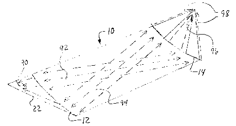
FIG.4 C&D shows a more recent prior art which uses a com-
bination of outer edge support webbing and transversal stren-
ght of the fabric in order to achieve a more level support of
the users. In this schematic of the support line of hammock
92, the fabric transversal line 94 is transmitting the support
action to the edges webbing 93, and spreader bars 96. Spread-
er bars 96 and 97 are ties to ropes and rings represented by
force lines 98 and 100. It can be seen that the combined con-
cavity of webbing 93 and transvere fabric line 94 allow for a
level longitudinal leveling at the drawback of being enclosed
into a deep transveral coocon which does not provide much or
any amount of comfort and relaxation.
FIG.4D is showing more specifically that the user of the
prior art 4C is laying near level lenghtwise; however as it
can be seen, the fabric is surrounding his body near complete-
ly, which means the user's shoulders are forced into a round
support position which is similar to the "banana hammock" or
laying in the bottom front or rear of a canoe; this and the
near total cut-off of peripherial vision is the extreme opp-
osite of what a comfortable relaxing outdoor enjoyment could
be.
FIG.5 detailed the prefered embodiment of the ComfortX
Hammock 110 where a spreader bar 114 is built whith a single
CA 02765491 2012-01-19
b
bend having an approximate radius of five feet in order to
promote a near perfect pull onto a fabric band 116 and 118; a
second spreader bar 113 is also made with a single bend radius
of only three to four feet because this bar hold a more verti-
cal position as seen in FIG.6A,and therefore only a partial
part of the bend is given for the fabric alignment. Similar-
ly, as in FIG.l, the fabric band 116 and 118 looped around
bars 113 and 114 and sewn to itself,covering the diagonal
fabric band is a rectangular fabric 154 at a sew line 126 and
128. Each end of the fabric 154 includes a flap 156 and 160
looped around a rope 158 and 162 sewn to itself at 157 and
161; the ropes 158 and 162 are tied around the spreader bar
113 and 114. These flaps are located for the head and the
feet;are adjustable by tightening or loosening the ropes 158
and 162. The spreader bar 113 is supported by a ring 130 via
a series of ropes 132 tied to the upper ends of bar 113 and
another rope 131 which is ajustable at ring 133 which carries
the load of the lower center holes 137 via the rope 135. The
reason for the separate and adjustable ropes support system
is in order to be able to "dial" how much support the occupant
wants for the lower back or the upper body. Spreader bar 114
is supported at the other end by a series of ropes 138 looped
into two widely spaced rings 136 to hold onto a tree 139 which
hold a spreader block 141 which has two hooks 145 anchoring
the rings 136. The hammock 110 also provide, through fabric
CA 02765491 2012-01-19 /
154,
an opening 163 which allows the occupant: to lay face down and
breathe easily with the head and body in line.
FIG.6A is a side view of FIG.5 of the preferred embodi-
ment of the invention; the hammock is shown in a relaxed pos-
ition with fabric band 116 and 118 edges in a near straight
line position; fabric 154 follows a more convolute shape since
the outer edges of band 116 and 118 are located 4 to 6 inches
higher than their inner edges at the spreader bar 113 and then
they criss-cross each other before they reach the other end
at spreader bar 114, therefore developing a staggered lift
especially strong from 1/3 to 2/3 the length of the hammock
bed.
Supporting the spreader bar 113 is the ring 130 with
ropes 132 tied to the upper end of the bar 113 and the rope
131 and 135 via ring 133 tied to the lower center section of
the curved bar 113. At the other end of the hammock, the
ropes 138 are tied to the rings 136 at one end and through
holes 140 through fabric band and spread bar 114. Side views
provide a precise view of how a flap 156 is linked to the
spreader bar with a rope 158. Same scenario at the other end
with a flap 160 supported at its end by a rope 162 tied to
the spreader bar 114.
The side view FIG.6B is showing the same hammock as
CA 02765491 2012-01-19
loaded by an occupant[not shown], and is based on the testing
of several prototypes such as the one seen in the picture in
FIG.6C, the description is similar as FIG.6A except that the
loaded diagonal band 116 and 118 are now lower by six to
eight inches which is about only one-half what a current ham-
mock does as in FIG.4B under a same occupant weight.
As seen in FIG.6A , the two flaps are around three to
four inches lower than the bedding, now under load as shown
in FIG.6B, the two flaps are now nearly horizontal with the
whole bedding and provides a near level surface from feet
to head.
The two point support at rings 136 can be provided by a
single tree with the spreader bloc 141 made of wood reinfor-
ced with an outer strap or wire of metal tie to the front
hooks 145. The bungee cord 143 is use to hold the block
141 during the initial set-up, only because once the hammock
is under a tension of two to four hundred pounds, the block
then is stable by friction to a very high degree.
As best seen in FIG.6C the photograph of the ComfortX
basic configuration is a side view similar to FIG.6B with two
exceptions.
A]The three point support is inverse with two
points supporting the feet and only one point at the head.
B]The head spreader bar is a straight wood bar ins-
tead of a curved one;however, this is similar to FIG.1 bar 12
CA 02765491 2012-01-19
and directly follows the invention design and configuration.
This photograph is showing how the occupant is resting on the
hammock with the upper body being supported by a near flat
surface of fabric.
FIG.7 is showing a third embodiment of the invention as
a partial top view of a double wide Comfort XX hammock as 170;
in this hammock, the upper rectangular fabric is omitted in
order to allow more clarity of the lower diagonal band which
are shown as a cut-off section for the same reason. This em-
bodiment shows a first diagonal band 172 which forms a wide
X with a second diagonal band 174; a second wide X is formed
by a third diagonal band 172' crossing over a fourth diagonal
band 174'. Both bands 172 and 172' overlap at a triangular
section 173, therefore reducing the width of the hammock;
similarly, the band 174 and 174' overlap at a triangular
section 175.
Other components of the hammock have similar character-
istics as previous embodiment such as a double curve spreader
bar 176 similar to bar 113 of FIG.5, and a straight spreader
bar 178 which provides the same function as spreader bar 12,
14, and 114 since all those bars are positioned in a horizon-
tal plane including the curved section in bar 114. It should
be noted that the horizontal plane bar end of the hammock is
preferred for the flatter fabric area it provides for the upper
CA 02765491 2012-01-19 it.
body of the user. This third embodiment is supported by a
single
ring 180 which supports a series of tension ropes 183 and 184;
the
ropes 183 are adjustable near spreader bar 176 thru a locking
device
182, all ropes tie to bar 176 and a series of four holes 177.
At the other end, the hammock is supported by bar 178
and a series of holes 179 with four ropes 188 ties to the two
rings 190. Located around a tree, 198 is a collapsable tri-
angle 192, this allows two hanging hooks 194 to carry the pull
of
hammock and a rigid two point support. The triangle 192 has at
least 2 hinges 196 and can be built from tubing material and
locked
at the 3rd intersection with it's own hook 194.
An alternative method to provide roll stability is to
provide the hammock with two clip-on legs 197 fastened to a
recess hub section 195 as part of bar 178.
FIG.8 is a fourth embodiment 200 of the ComfortX hammock
is shown as an alternative and lower cost two diagonal fabric
bands 202 and 204 slightly wider than in previous embodiment;
this configuration eliminates the need for the upper rectang-
ular fabric. This partial embodiment shows a double bend
spreader bar 206 around which the fabric 202 and 204 looped
around with fabric end at 212 and sewn to itself at line 214.
At mid-width, a double flap 216 from fabric 202 and 204 is
CA 02765491 2012-01-19
looped around itself up to ends 218 and sewn to itself at sew
line 220; a cut off line 219 gives some leeway into the amount
of sag provided by a group of ropes 221.
At the center of the diagonal band a few sewing line 232
provides extra strength and stability to the fabric, it also
allows a precise location for under knee pillow lift. The
hammock's other end is shown with a straight spreader bar 208
with fabric loop 222 ending at 224 and sewn at line 226; cen-
ter section is similar to the other end with a single layer
of fabric 204 and 202 forming a flap 224 before reaching bar
208, this fabric loop end at 226 and is sewn at line 228; a
series of ropes 230 are fastening the flap to the bar 208.
A breathing hole 234 and surrounding sewing allows for face
down use of the hammock.
Fabrication and assembly of this hammock is basic wood
working, fabric cutting, sewing, and mostly manual assembly
of the components together. Pre-production hammocks should
be made in order to eliminate any production difficulty and
reach a product with the correct characteristics. Assembly
of the 2 or 3 layers of fabric will need to be precise enough
in order to achieve shared load and stretch lenghtwise but
give approximately 5% extra material near the flap area at
each end from side to side; this extra material is important
as it permits a level support of the hammock occupant.
CA 02765491 2012-01-19
Abstract
A hammock design which provides increased lifting at its mid-length or medial
portion through a
combination of wide bands of fabric in a lengthwise X-shaped formation with a
curved or bent
spreader bar. In a preferred use, the spreader bar rises from a lower middle
part toward higher
raised ends. This hammock allows the user a comfortable positioning with
nearly horizontal
transverse support at the users shoulders and a nearly level position from
head to toe.
CA 02765491 2012-01-19
Comfort X Hammock
Cross-Reference to Related Applications
This application claims priority from provisional U.S. Patent Application
61/271,264, filed July
18, 2009.
Background of the Invention
This invention relates to hammocks, particularly one in which an occupant is
supported
by material suspended between at least two points. An occupant suspended above
the ground in
a hammock may rest from a few hours for daytime napping up to a full night
sleep in places
where the hammock is a substitute for a bed such as aboard ship or in some
countries.
Hammocks in general have been used for thousands of years, however most recent
improvements appear in the last 100 years.
Prior art patents show different concepts and inventions related to increase
level surface,
spreader bar improvements, variable tensioning of fabrics, specific fabric
shapes and asymmetric
position of fabric and spreader bars. Graham's Patent # 645,805, Potter's
Patent # 717,119,
Hall's Patent # 4,001,902, Fueslein's Patent # 4,021,868, Scott's Patent #
6,347,638, Eriksen's
Patent # 6,701,549, Hennessey's Patent # 6,865,757 and Helsdon's Patent
#7,020,915 each show
improvements to hammocks. These patents show various ways to achieve some
improvement of
comfort as less curvature lengthwise for the occupant usually at the detriment
of the lateral
flatness of the hammock. Some others are keeping the lateral flatness to the
detriment of a multi-
steep flatness lengthwise.
Most hammock materials used today have a strong longitudinal strength with low
elongation of around 2 to 5 percent in that direction which allows a person to
lie in the hammock
and be well supported, especially if a pre-tension of 20 to 100 lbs is made
upon installing the
hammock.
Many hammocks are so concave from side to side that any field of vision
horizontally is
gone and the occupant is constrained to resist a high level of side to side
pressure.
A final and important drawback to most patents using only a two-ring support
system, is
when a higher tension is applied on the rings in order to improve the level
lengthwise, a similar
decrease of stability is brought about making it nearly impossible to stay on
the hammock.
Brief Summary of the Invention
CA 02765491 2012-01-19
It is therefore a foremost object of this invention to provide a hammock where
the
supporting surface is substantially level both lengthwise and laterally at the
upper body level
where the occupant lies on the hammock for pleasure or sleeping purposes.
A second object of this invention is to provide a low cost but sophisticated
fabric support
system which is easy to use either recreationally or under more tension such
as sleeping surface
including a three point anchoring design allowing lengthwise level and high
stability combined
with ease of installation.
A third object of this invention is to provide a fabric structure with two
wide bands in an
X formation, which supports the weight of the occupant exactly where it is
more concentrated,
from 1 /3 to 2/3 of the hammock in its center as shown later on line force
diagram, Figure 4A.
A fourth object of this invention is to provide improved tensioning including
non-linear,
curved or bent spreader bars, the positioning of which can provide a near-
level surface for the
occupant. This elevation of the bar ends, which work similarly as a suspended
bridge, allows
easy adjustment of the hammock tension, comfort and level degree as desired.
Several other objects and advantages of this invention are to provide lateral
stability
through double anchoring at one end of the hammock via a single tree or post
with a triangle or a
spreader block which allows a two point anchoring system; a second way to
achieve this stability
is to provide one of the spreader bars with two clip-on legs free to rotate
and hold either end
from leaning side to side.
CA 02765491 2012-01-19
It is understood that 3 or 4 points anchoring is preferable, when possible.
Use of this
hammock in a house would preferably be fixed solid at the head with a double
short anchoring
system which allows tensioning while preserving full stability.
The preferred embodiments of the invention have been described; however
several other
embodiments based on the broad designs and configurations of the present
invention are
contemplated within the scope of the claims presented below.
A first non-illustrated arrangement is the solid attachment of one spreader
bar directly
onto a bedroom wall, a ship partition or an outdoor hammock support. In such a
situation only
one end would require a variable length attachment which can include a one or
two ring
structure, or not.
Another non-illustrated arrangement of the hammock is where the rectangular
fabric flap
would be self supporting without any attachment to the spreader bar; in this
case, the fabric
lateral strength combined with a certain extra length of fabric and an
appropriate hem with or without rope into the hem would provide the basic
comfort required.
A third arrangement is where the larger diagonal fabric band would include a
certain
degree of looseness at the location of the head and the feet.
Several other arrangements are possible through using the basic elements of
the first
embodiment and integrating these into the other embodiments especially the
third and fourth.
CA 02765491 2012-01-19
It is useful to note that these specific details to the invention embodiments
are already
known by the persons familiar with the construction of hammock structure and
construction.
The many advantages which are inherent to the embodiments structure are
obvious to the
one skilled in the art. Those embodiments are described herein illustratively
and are not meant
to limit the scope of the invention, therefore variation of the basic
embodiments is intended to be
encompassed by the following claims.
CA 02765491 2012-01-19
Brief Description of the Drawings
FIG.1 shows a top view of the hammock which forms the first embodiment when
combined with FIG.2B.
FIG.2A is a top view of the diagonal fabric bands of FIG.1.
FIG.2B is a top view of the upper fabric layer fastened to FIG. 1 in order to
complete
the
first embodiment.
FIG.3 is a side view of the first embodiment combining FIG.1 and FIG.2B
FIG.4A is a perspective view of the line of force acting in between support,
spreader
bar
and fabric of the 1st embodiment.
FIG.4B is a perspective view of a prior art line of force.
FIG.4C is a perspective view of another more recent prior art showing the line
of
force.
FIG.4D is a side view drawing of a photograph taken from a prior art patent
4C.
FIG.5 is a top view of preferred and second embodiment of the ComfortX
Hammock.
FIG.6A is a side view of the second embodiment shown in an unloaded position
FIG.6B is the same as FIG.6A except it is loaded (i.e. with an occupant)
FIG.6C is a photograph of a prototype of the ComfortX Hammock following the
CA 02765491 2012-01-19
second
embodiment configuration.
FIG.7 shows a top view of a double wide hammock made compact by overlapping
the
diagonal fabric band at the center of the hammock.
FIG.8 is a schematic view of a third embodiment built with only two pieces of
fabric.
CA 02765491 2012-01-19
List of Reference Numericals
single wide hammock 62 sew line
12 spreader bar 64 sew line
14 spreader bar 66 sew line
16 large band of fabric 68
18 large band of fabric 70 force line
sew line 72 force line
22 loop 74 force line
24 loop 76 force line
26 sew line 78
28 sew line 80 hammock
single ring 82 force line
32 supporting ropes 84 spreader bar
34 anchor holes 86 force line
36 double rings 88 spreader bar
38 supporting ropes 90 force line
anchor holes 92 hammock
42 fabric end 93 edges webbing
44 fabric end 94 transversal line
46 material holes 96 spreader bar
48 material holes 97 spreader bar
rectangular fabric 98 force lines
52 medium width hem 100 force lines
54 adjustable flap 102
56 sew line 104
58 variable length rope 106
fix flap 108
CA 02765491 2012-01-19
List of Reference Numer_Lcals
110 ComfortX Hammock 145 two hooks
112 146
113 spreader bar 148
114 spreader bar 150
116 fabric band 152
118 fabric band 154 rectangular fabric
120 sew line 156 flap
122 157 sew line
124 sew line 158 rope
126 sew line 160 flap
128 sew line 161 sew line
130 ring 162 ring
131 ropes 163 an opening
132 ropes 164 sew line
133 ring 166 sew line
134 168
135 rope 170 double wide hammock
136 spaced rings 172 diagonal band
137 lower center holes 1721 diagonal band
138 series of ropes 173 triangle section
139 tree 174 diagonal band
140 holes 1741 diagonal band
141 spreader block 175 triangular section
142 176 double curve bar
143 bungee cord 177 four holes
144 178 straight bar
179 series of holes
CA 02765491 2012-01-19
List of Reference Numericals
180 210
182 locking device 212 fabric end
183 tension ropes 214 sew line
184 tension ropes 216 double flap
186 double fabric 218 fabric ends
188 four ropes 219 cut off line
190 two rings 220 sew line
192 collapsible triangle 221 group of ropes
194 two hanging hooks 222 fabric loop
195 recess hub section 224 fabric end
196 two hinges 226 sew line
197 clip-on legs 228 sew line
198 tree 230 series of ropes
200 fourth embodiment 232 sewing line
202 diagonal fabric band
204 diagonal fabric band
206 double bend spreader bar
208 straight spreader bar