Note: Descriptions are shown in the official language in which they were submitted.
CA 02765600 2011-12-14
WO 2010/150222 PCT/IB2010/052896
1
A POSITIONING GUIDE AND A FEMUR BONE CUTTING GUIDE SYSTEM
FIELD OF INVENTION
This invention relates to a positioning guide for use with a bone cutting
guide
assembly and to a femur bone cutting guide system for use in guiding the
cutting of a
patient's femur bone during a knee replacement surgical procedure. In this
specification the terms knee replacement surgery and knee replacement surgical
procedure shall be interpreted sufficiently broadly to include knee
resurfacing and
knee resurfacing surgical procedure, respectively.
SUMMARY OF INVENTION
According to a first aspect of the invention, there is provided a positioning
guide for use
with a bone cutting guide assembly for use in a knee replacement surgical
procedure
for guiding the cutting of at least one prosthetic joint locating face in an
end region of a
femur of a human patient, from which a portion of bone is to be removed,
thereby to
allow for the secure fitment of a prosthetic joint to the femur in a
predetermined
orientation which approximates the anatomical normality of the patient's knee
joint, the
bone cutting guide assembly including a bone cutting guide having at least one
cutter
CA 02765600 2011-12-14
WO 2010/150222 PCT/IB2010/052896
2
guide formation for guiding a cutter for cutting said prosthetic joint
locating face in said
end region of the femur; and guide mounting means which can be fixedly secured
to
the femur and which includes mounting means to which the bone cutting guide is
releasably mounted for releasably mounting the bone cutting guide relative to
the
femur,
the positioning guide including:
a bone mounting structure in the form of a moulding which is constructed from
anatomical data obtained of said end region of the femur so as to define
complementary locating formations which correspond to anatomical formations of
said
end region of the femur, thereby to provide for the secure fitment of the bone
mounting
structure to said end region of the femur; and
at least one attachment post which is fixed to and which projects outwardly
from the
bone mounting structure and to which the bone cutting guide of the bone
cutting guide
assembly is releasably mounted, in use, for positioning the bone cutting guide
assembly as a unit, relative to the femur in an arrangement wherein the cutter
guide
formation of the bone cutting guide is located in a predetermined position
relative to the
femur so as to facilitate the cutting of said prosthetic joint locating face
in the femur
thereby to provide for the fitment of the prosthetic joint thereto.
The attachment post may have a releasable connecting formation for releasably
connecting the attachment post to said bone cutting guide.
The positioning guide may include a pair of attachment posts.
According to a second aspect of the invention, there is provided a femur bone
cutting
guide system for use in a knee replacement surgical procedure for cutting at
least one
prosthetic joint locating face in an end region of a femur bone of a human
patient, from
which a portion of bone is to be removed, thereby to allow for the secure
fitment of a
prosthetic joint to the femur in a predetermined orientation which
approximates the
anatomical normality of the patient's knee joint, the bone cutting guide
system including:
CA 02765600 2011-12-14
WO 2010/150222 PCT/IB2010/052896
3
a bone cutting guide assembly including:
a) a bone cutting guide having at least one cutter guide formation for guiding
a cutter for cutting said prosthetic joint locating face in said end region of
the femur; and
b) guide mounting means which can be fixedly secured to the femur and
which includes mounting means to which the bone cutting guide is
releasably mounted for releasably mounting the bone cutting guide
relative to the femur when the guide mounting means is secured thereto;
and
a positioning guide as hereinabove described in accordance with the first
aspect of the
invention, for mounting the bone cutting guide assembly to the femur bone,
with the guide mounting means being fixedly secured to the femur bone after
mounting of the bone cutting guide assembly to the attachment post, with the
attachment post, the guide mounting means and the bone cutting guide being
configured to permit separation of the bone cutting guide from the attachment
post
and from the guide mounting means to facilitate removal of the positioning
guide, and
remounting of the bone cutting guide to the guide mounting means after removal
of
the positioning guide.
The bone cutting guide may include attachment post mounting means for
releasably
mounting the bone cutting guide to the attachment post of the positioning
guide.
The bone cutting guide may include complementary mounting means for releasably
mounting the bone cutting guide to the mounting means of the guide mounting
means.
The positioning guide may have a pair of attachment posts and the attachment
post
mounting means of the bone cutting guide may be in the form of a pair of
complementary attachment post mounting formations.
CA 02765600 2011-12-14
WO 2010/150222 PCT/IB2010/052896
4
The complementary mounting means of the bone cutting guide may be in the form
of
a pair of complementary mounting formations, each mounting formation being
spaced
towards opposite side regions of the cutting guide.
The guide mounting means of the bone cutting guide assembly may be in the form
of
a pair of side mounting plates, each side mounting plate having bone mounting
means for releasably mounting the plate to a different opposite side region of
the
femur, in use.
The cutting guide may comprise a first cutting guide component and a second
cutting
guide component, the cutting guide components having complementary releasable
securing formations for releasably securing the cutting guide components to
one
another.
BRIEF DESCRIPTION OF THE DRAWINGS
Further features of the invention are described hereinafter by way of a non-
limiting
example of the invention, with reference to and as illustrated in the
accompanying
diagrammatic drawings. In the drawings:
Figure 1 shows a fragmentary perspective view of the bones of a human leg in
their
anatomically normal position;
Figure 2 shows a lower end view of the femur bone of the human leg shown in
Figure
1;
Figure 3 shows a fragmentary perspective view of the femur of the human leg of
Figure 1, which has been cut to fit a femoral component of a knee prosthesis
thereto;
Figure 4 shows a fragmentary perspective view of the knee joint of Figure 1 to
which
a prior art knee prosthesis is connected;
CA 02765600 2011-12-14
WO 2010/150222 PCT/IB2010/052896
Figure 5 shows a fragmentary sectional view of the prior art knee prosthesis
of Figure
4, sectioned along section lines V - V of Figure 4;
Figure 6 shows a top view of a femoral sizing guide of a conventional prior
art knee
bone cutting guide system, the femoral sizing guide shown located against the
femur
of Figure 2;
Figure 7 shows a top view of an alignment guide rod of the conventional prior
art
knee cutting guide system of Figure 6, showing the alignment guide rod
inserted into
a hole drilled into the femur of Figure 6;
Figure 8 shows a fragmentary perspective view of a guide of the conventional
prior
art knee bone cutting guide system of Figure 6, showing the guide mounted on
the
alignment guide rod of Figure 7;
Figure 9 shows a fragmentary cross-sectional view of the femur bone of Figure
6,
showing a mounting base of the conventional prior art knee cutting guide
system of
Figure 6 mounted onto the femur of Figure 6;
Figure 10 shows a fragmentary front view of a custom-made prior art knee-
cutting
guide;
Figure 11 shows a fragmentary side view of the custom-made prior art knee
cutting
guide of Figure 10 connected to a human femur and tibia bone;
Figure 12 shows a fragmentary side view of the custom-made prior art knee
prosthesis, connected to the cut bone of Figure 11;
Figure 13 shows a fragmentary cross sectional view of a positioning guide of a
bone
cutting guide system in accordance with the invention, connected to the lower
end
region of a femur;
Figure 14 shows a perspective view of the bone cutting guide of the bone
cutting
guide system releasably connected to the positioning guide of Figure 13;
CA 02765600 2011-12-14
WO 2010/150222 PCT/IB2010/052896
6
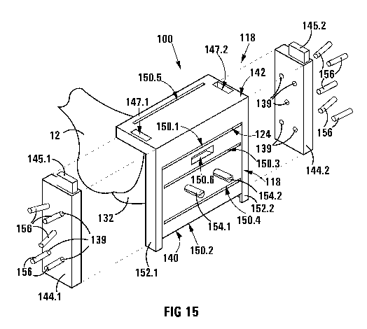
Figure 15 shows an exploded perspective view of the bone cutting guide system,
disassembled, in accordance with the invention;
Figure 16 shows a perspective view of the bone cutting guide system of Figure
15,
assembled;
Figure 17 shows a sectional side view of the bone cutting guide system of
Figure 16,
sectioned along section lines XVII - XVII of Figure 16;
Figure 18A shows a perspective view of a second embodiment of a femur bone
cutting guide system in accordance with the invention;
Figure 18B shows a perspective view of the adaptor of the second embodiment of
the femur bone cutting guide system shown in Figure 18A, mounted to the
positioning guide thereof; and
Figure 18C shows a perspective view of the conventional prior art knee cutting
guide
system of Figure 6 mounted to the adaptor of Figure 18B.
DETAILED DESCRIPTION OF THE DRAWINGS
The present invention relates to a femur bone cutting guide system for use in
guiding
the cutting of a patient's femur bone during a knee joint replacement surgical
procedure.
The patient's knee joint may require replacement due to injury or
deterioration
caused by aging, or certain debilitating conditions, such as, for example,
arthritis.
An anatomically normal knee joint will be described below.
Figure 1 shows a perspective view of the bones of a human leg in their
anatomically
normal position. The bones include a femur 14 and a tibia 16, shown in their
normal
position defining an anatomically normal knee-joint 17.
CA 02765600 2011-12-14
WO 2010/150222 PCT/IB2010/052896
7
The femur 14 has a lower extremity 12 at its distal end 41 and a femoral head
55 and
a neck 49, at its proximal end 47. The femur 14 defines a longitudinal axis
26.
A mechanical axis 24 of the leg is also shown in Figure 1, the mechanical axis
24
extends from the centre of the head of the femur 55 and through the centres of
the
knee joint 17 and the ankle joint (not shown). In its anatomically normal
position, the
longitudinal axis 26 of the femur 14 is offset relative to the mechanical axis
24 by a
deviation angle a of approximately 69 as shown in Figure 1. In its
anatomically
normal position, a longitudinal axis of the tibia 16 thus corresponds with the
mechanical axis 24.
Figure 2 shows a lower end view of the lower extremity 12 of the femur 14
showing a
transverse line 21 extending between the apices of anatomically normal
posterior
condyles 11. Figure 2 also shows a transverse axis 25 which is disposed
parallel to
the transverse line 21 and which extends through an apex of an intercondyloid
fossa
15 of the lower extremity 12 of the femur 14. An external rotation axis 23 is
angularly
offset from the transverse axis 25 by an angle R of external rotation, the
significance
of which will be explained below.
Having described the normal anatomy of the knee 17, the cutting of the
patient's joint
bones during a typical knee joint replacement surgical procedure is described
below.
During joint replacement surgery, at least one prosthetic joint locating face
must be
cut in an end region of the lower extremity of the femur by removing a portion
of bone,
so as to allow for the secure fitment of a prosthetic joint to the lower
extremity of the
femur in a predetermined orientation which approximates the anatomical
normality of
the patient's knee.
The cutting of the bones of the knee joint 17 includes the cutting of the
lower
extremity 12 of the femur 14 and the upper extremity of the tibia 16.
With reference to Figure 3 of the drawings, the cuts made to the lower
extremity 12 of
the femur 14 during a knee joint replacement surgical procedure, are shown.
Figure
CA 02765600 2011-12-14
WO 2010/150222 PCT/IB2010/052896
8
3 shows a lower extremity 12 which has been cut to form prosthetic joint
locating
faces 46 in an end region 41 of the lower extremity 12 of the femur 14. The
cuts
include an anterior cut 46.1, an anterior chamfer 46.2, a posterior chamfer
46.3, a
posterior cut 46.4, a distal cut 46.5 and a notch 46.6. The orientation and
position of
the cuts 46 are critical to the fitment of the prosthesis, which must be
fitted in a
configuration which approximates the anatomical normality of the knee joint,
as will
be explained below.
With regards to the cutting of the tibia 16 of the knee joint 17, the tibia 16
is typically
cut so as to define a flat face which extends perpendicularly with respect to
the
longitudinal axis of the tibia which coincides with the mechanical axis 24.
A number of different knee joint prostheses are supplied by different
manufacturers,
each manufacturer requiring different cutting configurations required to fit a
particular
prostheses.
Referring to Figures 4 and 5, there is shown a typical conventional prior art
knee
prosthesis, which comprises two components, namely, a femoral component 10.1
and a tibial component 10.2.
Figures 4 and 5 show the lower extremity 12 of the femur 14 and the upper
extremity
of tibia 16 illustrating cut joint locating faces 46 and 22.2 of the femur 14
and tibia 16,
respectively. The femoral component 10.1 includes a generally cup-shaped
receiving
formation 13.1 which defines a number of angled faces 20.1. The tibial
component
10.2 includes a generally cup-shaped receiving formation 13.2 which defines a
flat
locating face 20.2. The cut locating faces 46 and 22.2 are securely located
and
cemented in the receiving formations 13.1 and 13.2, respectively, in a
configuration
which approximates the anatomical normality of the patient's knee joint 17.
To approximate anatomical normality of the patient's knee joint, the cut faces
46 are
configured such that the prosthesis 10.1, once fitted, allows for the
longitudinal axis
of the tibia 16 to be angularly offset by an angle a of between 59 and 79 from
the
longitudinal axis 26 of the femur 14. The angle a provides for the alignment
of the
longitudinal axis of the tibia 16 with the mechanical axis 24 of the leg
thereby to
CA 02765600 2011-12-14
WO 2010/150222 PCT/IB2010/052896
9
approximate the anatomical normality of the knee joint. Furthermore, the cut
locating
faces 46 are configured such that the femoral component 10.1, once fitted,
allows for
the angular rotation of the femoral component 10.1 by an angle R of external
rotation
of 39 relative to the transverse axis 25 as shown in Figure 2.
With reference to Figures 6, 7, 8 and 9, a conventional prior art knee cutting
guide
system 8, is shown. The prior art knee cutting guide system is used for
cutting the
joint locating faces 46 required for fitment of a particular prosthesis. Each
prosthesis
manufacturer provides a bone cutting guide system to facilitate cutting of the
lower
extremity 12 of the femur 14 in a particular configuration in order to fit the
femoral
component of the prosthesis to the patient. The conventional prior art cutting
guide
system includes a femoral sizing guide 37, a guide 34; a pair of mounting base
plates
27, a mounting base 44; milling and cutting guides 45; and an alignment guide
comprising a rod 40, the purpose of which will be described below.
In order to fit the knee prosthesis 10 to the patient, the patient is
anesthetised and
the skin and tissue covering the knee is cut and the knee joint is dislocated
in order
to expose the lower extremity 12 of the femur 14.
As a first step, with reference to Figure 6, the longitudinal axis 26 of the
femur 14 is
estimated by drilling hole 38 into the lower extremity 12 of the femur 14 and
along the
length of the shaft of the femur 14 thereby reaming the marrow cavity of the
femur 14.
As a second step, with reference to Figure 7, guide arms 19.1 and 19.2, of the
femoral sizing guide 37 are located against the posterior condyles 11 of the
lower
extremity 12 of the femur 14, so as to position hole drilling guides 43.1 and
43.2
relative to the lower extremity 12 of the femur 14 as shown in Figure 6. A
pair of
reference holes are then drilled into the lower extremity 12 of the femur 14
using hole
drilling guides 43.1 and 43.2 to guide the drilling procedure.
As a third step, the alignment guide rod 40 is then hammered into the hole 38,
as
shown in Figures 7 and 8. If correctly fitted, a longitudinal axis of the
alignment guide
rod 40 thus coincides with the longitudinal axis 26 of the femur 14. The
alignment
guide rod 40 includes plate defining alignment formations 53.1 and 53.2. The
CA 02765600 2011-12-14
WO 2010/150222 PCT/IB2010/052896
alignment guide rod 40 and plate are rotated until the drilled reference holes
are
aligned with the alignment formations 53.1 and 53.2, thereby to ensure that
the
alignment guide rod 40 is rotated relative to transverse axis 25, by an angle
R of
external rotation of 3 .
With reference to Figure 8, the alignment guide rod 40 is used to guide the
location of
the guide 34 relative to the bone. More particularly, the guide 34 is mounted
onto the
pair of mounting base plates 27 and the guide 34 is mounted onto the alignment
guide rod 40. The guide 34 is then displaced relative to the alignment guide
rod 40,
to approximate the mechanical axis 24 of the femur 14. The mechanical axis 24
is
estimated at an angle a of deviation of between 5 and 79 off-set from the
approximated longitudinal axis 26, i.e. from the longitudinal axis of the
alignment
guide 40.
Once the guide 34 has been aligned to incorporate the abovementioned angles,
the
pair of mounting base plates 27 mounted onto the guide 34 are then connected
to the
femur 14 by means of pins (not shown). The guide 34 and alignment guide rod 40
are removed once the mounting base plates 27 have been secured to the
patient's
femur 14.
To remove the alignment guide rod 40 from the lower extremity 12 of the femur
14,
the guide 34 is disconnected and removed from the mounting base plates 27 and
thereafter the alignment guide rod 40 is removed from the femur 14. After
removing
the alignment guide rod 40, the milling and cutting guides 45 are connected to
the
base plates 27.
As shown in Figure 9, the milling and cutting guides 45, guide cutters for
cutting of
the lower extremity 12 of the femur 14. More particularly, the milling and
cutting
guides 45 provides guiding faces 36.1, 36.2, 36.3 and 36.4 for guiding the
milling and
cutting tools for cutting the joint locating faces 46 into the lower extremity
12.
Once the cuts have been affected, the milling and cutting guides 45 and
mounting
base 44 are removed from the mounting base plates 27 and the mounting base
CA 02765600 2011-12-14
WO 2010/150222 PCT/IB2010/052896
11
plates 27 are removed from the lower extremity 12 of the femur 14, by removal
of the
pins (not shown).
It will be appreciated that the success of the procedure is critically
dependent upon
the judgement and estimation of the surgeon, as the longitudinal axis 26 of
the femur
14 is estimated and thereafter a mechanical axis 24 is determined relative to
the
estimated anatomical axis 26. As such, there is a need for a more precise
manner of
determining the correct location and configuration of the cuts 46 made to the
lower
extremity 12 of the femur 14. It will also be appreciated that the
configuration of
cutting guides will vary from one prosthesis manufacturer to another. Surgeons
therefore become experienced in fitting prostheses from particular
manufacturers.
The prostheses 10 described thus far are commercially available in a variety
of sizes
to suit the size of the patient. The prosthesis 10 is in no way specific to a
particular
patient and is merely selected to be of a suitable size.
A more recent development in knee replacement surgery is a so-called patient-
specific procedure, which, in some respects is an improvement of the procedure
described above. Referring to Figure 10, 11 and 12, the patient-specific
procedure
involves the manufacture of a patient-specific knee replacement components of
prosthesis 48.1 and 48.2, and an associated custom-made cutting guide system
which includes cutting guide components 50.1 and 50.2. Each cutting guide
component 50.1 and 50.2 includes receiving formations (not shown), which
conform
to the shape and configuration of a particular patient's knee joint. Each of
the cutting
guide components 50.1 and 50.2 define cutting guide formations 51.1 and 51.2,
respectively.
The patient-specific procedure begins with a radiographic scan, which is
performed
to take precise measurements of a patient's knee. Computer software is then
used
to analyse the radiographic data and to build a 3-dimensional model of the
patient's
knee (not shown). Abnormalities in the knee caused by arthritis or other
debilitating
ailments, are taken into account, and digitally removed thereby to approximate
the
knee to its anatomical normality.
CA 02765600 2011-12-14
WO 2010/150222 PCT/IB2010/052896
12
The computerised 3-D image of the prosthesis to be used in the patient's
surgery is
then shape matched to the anatomical model. This assists in determining the
exact
size and placement of the implant, based on the patient's own "normal"
anatomy.
Using the above information, the patient-specific prostheses 48.1 and 48.2 and
corresponding custom-made bone cutting guides 50.1 and 50.2 are then
manufactured specifically for the patient.
The custom made cutting guide components 50.1 and 50.2 have connecting
formations (not shown) which correspond with the shape and configuration of
the
lower extremity 12 of the femur and of the upper extremity of the tibia 16,
respectively,
and which are attached to the ends of the lower extremity 12 and tibia 16 as
shown in
Figure 11.
The custom-made bone cutting guides 50.1 and 50.2 are fitted to the lower
extremity
12 of the femur 14 and the upper extremity of the tibia 16, respectively, as
shown in
Figure 11. The cutting guide formations 51.1 and 51.2 are used for guiding
cutters
(not shown) used to cut the lower extremity 12 of the femur and the upper
extremity
of the tibia 16, respectively. More particularly, each cutting guide 50.1 and
50.2
guides the cutting of corresponding faces (not shown) which are cut into the
extremities of the femur 14 and tibia 16, respectively. The cut faces
correspond with
and locate against corresponding faces (not shown), defined on the prostheses
48.1
and 48.2, respectively.
It will be appreciated that the success of the prior art patient-specific
surgical
procedure, described above, thus relies less on the skill and estimating
abilities of the
surgeon than is the case with the conventional prior art procedures described
above.
A known disadvantage of the patient-specific knee prosthesis is that each
prosthesis
48.1 and 48.2 and the bone cutting guides 50.1 and 50.2 have to be uniquely
custom-made and cannot be tested and developed as extensively as the
conventional prostheses 10.1 and 10.2. Furthermore, higher costs and longer
production time is required for producing the patient-specific prosthetic knee
device
48 and associated custom-made bone cutting guides 50.1 and 50.2.
CA 02765600 2011-12-14
WO 2010/150222 PCT/IB2010/052896
13
A need has been identified for a device enabling a surgeon to use the
conventional
knee prostheses 10.1 and 10.2, together with a bone cutting guide configured
to
reliably locate the prostheses 10.1 and 10.2 in an optimum position which
approximates the anatomical normality of the patient's knee joint 17 for a
particular
patient and without the need for estimation. Furthermore, a need exists for a
reliable
bone cutting guide system, which can be used, with a number of different
prostheses
supplied by different manufacturers of prostheses thereby allowing the surgeon
a
greater degree of choice in the selection of the most appropriate prosthesis.
Having described the prior art knee replacement prostheses and procedures
above,
various embodiments of a bone cutting guide system in accordance with the
invention will now be described below.
With reference to Figures 13 to 17 of the drawings, a femur bone cutting guide
system, in accordance with the invention, is designated generally by the
reference
numeral 100. The bone cutting guide 100 is adapted for use in cutting
prosthetic joint
locating faces in a lower end region of a femur to facilitate the fitment of a
prosthetic
joint to the femur.
The femur bone cutting guide system 100 includes a bone cutting guide assembly
118 and a positioning guide 111 for mounting the bone cutting guide assembly
118 to
the lower extremity 12 of the femur bone 14.
The bone cutting guide assembly 118 includes a bone cutting guide 124 and
guide
mounting means comprising a pair of side mounting plates 144.1, 144.2 defining
holes 139 therethrough and securing pins 156 for securing the side mounting
plates
to the femur 14.
The bone cutting guide 124 defines a number of cutter guide formations for
guiding a
cutter 119 while cutting the prosthetic joint locating faces 46 in the lower
extremity 12
of the femur 14. The bone cutting guide 124 includes a first cutting guide
component
140 and a second cutting guide component 142.
CA 02765600 2011-12-14
WO 2010/150222 PCT/IB2010/052896
14
The first cutting guide component 140 is in the form of a plate which defines
attachment post mounting formations in the form of a pair of holes 143.1 and
143.2.
The component 140 has releasable mounting formations defined on opposite side
edges of the component 140 in the form of tongues 148.1 and 148.2. The cutter
guide formations defined by the first cutting guide component 140 comprise an
anterior abutment guide surface 150.1, a posterior abutment guide surface
150.2, a
posterior chamfer slot 150.3, an anterior chamfer slot 150.4 and a notch slot
150.6.
The second cutting guide component 142, with reference particularly to Figure
15,
defines a pair of mounting formations in the form of a pair of slots 147.1 and
147.2 for
releasably mounting the component 142 to the component 140. The component 142
defines a cutter guide formation in the form of a distal cutting slot 150.5.
The second
cutting guide component 142 further defines a pair of spaced arms 152.1 and
152.2
disposed at opposite sides thereof. Each arm 152.1 and 152.2 defines
releasable
mounting formations in the form of a groove (not shown), within which a
different one
of the corresponding tongues 148.1 and 148.2 of the first cutting guide
component
140 are slidingly received when the first cutting guide component 140 and the
second
cutting guide component 142 are assembled.
The side mounting plates 144.1, 144.2 have mounting means in the form of
mounting
formations 145.1 and 145.2, respectively, which are received within the slots
147.1
and 147.2, respectively, of the component 142.
The positioning guide 111 comprises a bone mounting structure in the form of a
moulding 132 and a pair of attachment posts 154.1, 154.2 which are fixed to
and
which project outwardly from the moulding 132 and to which the bone cutting
guide
124 can be releasably mounted as will be explained below.
The moulding 132 is constructed from anatomical data obtained of the end
region 41
of the lower extremity 12 of the femur 14 prior to surgery. The moulding 132
is thus
constructed prior to the surgical procedure, from anatomical data obtained by
means
of a radiographic scan of the patient's lower extremity 12, from which scan, a
three-dimensional model of the patient's lower extremity 12 is constructed
(not
shown). The moulding defines complementary locating formations 134 which
CA 02765600 2011-12-14
WO 2010/150222 PCT/IB2010/052896
correspond to anatomical formations 136 defined on the end region 41 of the
lower
extremity 12 of the femur 14. The locating formations 134 provide for secure
fitment
of the moulding 132 to the end regions 41 of the lower extremity 12 of the
femur 14 in
a specific position. More particularly, the locating formations 134 of the
moulding 132
are configured to conform and correspond to the shape and configuration of the
lower extremity of the femur. The moulding 132 is securely fitted, in use,
onto the
lower extremity 12 of the femur 14 with the complementary locating formations
134 of
the moulding 132 corresponding with anatomical formations 136 defined on the
end
region 41 of the lower extremity 12 of the femur 14.
The attachment posts 154.1 and 154.2 have split ends and define connecting
formations in the form of circumferential grooves 189, the purpose of which
will be
described below. The exact location and configuration of the attachment posts
154.1
and 154.2 is pre-determined when the moulding 132 is constructed.
The use of the positioning guide 111 and the bone cutting guide system 100
will now
be explained with reference to Figures 13 to 17. With reference to Figure 13,
the
moulding 132 of the positioning guide 111 is fitted to the lower extremity of
the femur
as described above.
The locating formations 134 on the inner side of the moulding 132 correspond
with
the natural geometry of lower extremity 12. The position of the attachment
posts
154.1 and 154.2 is thus fixed relative to the femur.
With reference to Figure 14, the first cutting guide component 140 is mounted
to the
moulding 132 by locating the attachment posts 154.1 and 154.2 within the holes
143.1 and 143.2 thereby to locate the first cutting guide component 140 with
respect
to the lower extremity 12 of the femur 14. The attachment posts 154.1 and
154.2
thus provide for location of the first cutting guide component 140 and thereby
the
second cutting guide component 142 of the cutting guide 124, when assembled to
the component 140, in a pre-determined position relative to the lower
extremity 12 of
the femur 14 to be cut.
CA 02765600 2011-12-14
WO 2010/150222 PCT/IB2010/052896
16
Figure 15 shows the second guide component 142 mounted to the first cutting
guide
component 140. The component 142 is releasably mounted to the component 140
by sliding the tongues 148.1 and 148.2 projecting from opposite sides of the
component 140 into the grooves defined in the arms 152.1 and 152.2 of the
component.
The side mounting plates 144.1, 144.2 are then connected to the component 142
by
locating connecting formation 145.1 within slot 147.1 and by locating
connecting
formation 145.2 within slot 147.2 of the second cutting guide component 142.
The
side mounting plates 144.1, 144.2 are secured to opposite sides of the lower
extremity 12 of the femur 14 by inserting the mounting pins 156 through the
holes
139 and into the femur 14. Once the side mounting plates 144.1 and 144.2 are
fixedly secured to the lower extremity 12 of the femur 14 by means of the
mounting
pins 156, the bone cutting guide assembly 118 is securely located relative to
the
lower extremity 12 of the femur 14 as illustrated in Figure 16.
The moulding 132 must be removed from its attachment to the patient's lower
extremity 12 once the mounting plates 144.1, 144.2 have been secured to the
femur
14, in order to facilitate cutting of the lower extremity 12 of the femur 14.
In order to
remove the moulding 132, the component 142 is separated from the guide
component 140 by sliding the component 142 upwardly and away from the
component 140. The component is then separated from the attachment posts of
the
moulding 132. The moulding 132 is then removed from the femur 14 leaving only
the
side mounting plates 144.1 and 144.2 fixed to the lower sides of the lower
extremity
12 of the femur 14 by means of the mounting pins 156.
Once the moulding 132 has been removed, the component 140 is then remounted to
the side mounting plates 144.1 and 144.2, and the component 142 is remounted
to
the component 140.
With reference to Figure 17, the components 140 and 142 are located in a
predetermined spacial relationship with respect to the lower extremity 12 of
the femur
14 providing for the accurate cutting of the lower extremity 12 using cutter
119. The
cutter is guided by the anterior abutment guide surface 150.1, the posterior
abutment
CA 02765600 2011-12-14
WO 2010/150222 PCT/IB2010/052896
17
guide surface 150.2, the posterior chamfer slot 150.3, the anterior chamfer
slot 150.4,
the distal cutting slot 150.5 and the notch slot 150.6.
The bone cutting guide assembly 118 is used to guide cutting devices 119 to
cut the
lower extremity 12 to produce the anterior cut 46.1, the posterior cut 46.4,
the
posterior chamfer 46.3, the anterior chamfer 46.2, the distal cut 46.5 and the
notch
46.6 as shown in Figure 3.
It will also be appreciated that prior to the surgery, various measurements
and
calculations are performed in order to determine the optimal location and
orientation
of the prosthesis 10.1 for the specific patient's anatomy. The precise
location and
orientation of the attachment posts 154.1 and 154.2 determines the exact
position of
the bone cutting guide 124 and thereby the position and configuration of the
cuts
forming the joint locating faces 46 on the lower extremity 12 of the femur.
The invention extends to the bone mounting structure as defined and described
hereinabove.
The invention also extends to the bone cutting guide 124 and to the bone
cutting
guide assembly 118 as defined and described hereinabove.
With reference to Figures 18A, 18B and 18C of the drawings, another embodiment
of
a femur bone cutting guide system, in accordance with the invention, is
designated
generally by the reference numeral 190.
The femur bone cutting guide system 190 includes a bone cutting guide assembly
194 and a positioning guide in the form of the positioning guide 111 of the
femur
bone cutting guide system 100, for mounting the bone cutting guide assembly
194 to
the lower extremity 12 of the femur bone 14.
The bone cutting guide assembly 194 includes a bone cutting guide and guide
mounting means comprising the pair of prior art mounting base plates 27 of the
prior
art knee cutting guide system 8 as illustrated in Figures 6, 7, 8 and 9. The
prior art
mounting base plates 27 are best shown in Figure 8.
CA 02765600 2011-12-14
WO 2010/150222 PCT/IB2010/052896
18
The bone cutting guide includes a first cutting guide component in the form of
an
adaptor 113, a second cutting guide component in the form of the milling and
cutting
guides 45 of the prior art knee cutting guide system 8 and a third cutting
guide
component in the form of the guide 34 of the prior art knee cutting guide
system 8.
The adaptor 113 defines a pair of apertures 191.1, 191.2 for releasably
receiving the
attachment posts 154.1, 154.2 of the positioning guide 111 therethrough; and
defines
a socket 192 for releasably receiving the connecting formations 193 of the
prior art
guide 34 therethrough.
The use of the femur bone cutting guide system 190 will be described below
with
reference to Figures 18A, 18B and 18C of the drawings. In use, the positioning
guide
111 is mounted to the lower extremity 12 of the femur 14, in the same manner
as is
described above in relation to femur bone cutting guide system 100. The
adaptor
113 is then mounted to the positioning guide 111 by receiving the attachment
posts
154.1, 154.2 of the positioning guide 111 through the pair of apertures 191 of
the
adaptor 113. The conventional prior art guide 34 is then mounted to the
adaptor 113
by receiving connecting formations 193 of the prior art guide 34 through the
socket
192 of the adaptor 113. Once the conventional prior art guide 34 is correctly
located
relative to the lower extremity 12 of the femur 14, the pair of mounting base
plates 27
of the conventional prior art knee cutting guide system are connected to the
guide 34.
After the base plates 27 are connected to the guide 34, the base plates 27 are
fastened to the femur 14 by means of pins 196, as shown in the drawings. The
guide
34 is then removed from its mounting to the base plates 27, in order to allow
for the
removal of the positioning guide 111 from its attachment to the lower
extremity 12 of
the femur 14. After the positioning guide 111 is removed, the guide 34 is re-
mounted
to the base plates 27 as shown in the drawings and the milling and cutting
guides 45
are re-mounted to the guide 34, to commence cutting procedures.
It will be appreciated that the femur bone cutting guide system 190 provides a
non-
invasive manner of accurately locating the prior art guide 34 and the milling
and
cutting guides 45 of the prior art knee cutting guide system relative to the
femur 14
bone. Furthermore, it will be appreciated that the bone cutting guide system
190
CA 02765600 2011-12-14
WO 2010/150222 PCT/IB2010/052896
19
ameliorates the degree of estimation previously required to locate the guide
34 and
the milling and cutting guides 45 of the prior art knee cutting guide system
relative to
the lower extremity 12 of the femur 14.