Note: Descriptions are shown in the official language in which they were submitted.
CA 02765673 2011-12-15
WO 2010/134926 PCT/US2009/045075
Page 1
ACIDIC GAS CAPTURE BY DIAMINES
BACKGROUND
As concerns of global climate changes spark initiatives to reduce carbon
dioxide
emissions, its economic removal from gas streams is becoming increasingly
important.
Removal by absorbtion/stripping is a commercially promising technology, as it
is well suited
to sequester carbon dioxide (C02). Such carbon dioxide emissions may be
produced by a
variety of different processes, such as the gas stream produced by coal-fired
power plants.
The removal of CO2 can be an expensive process, potentially increasing the
cost of electricity
by 50% or more. Therefore, technology improvements to reduce the costs
associated with the
removal are highly desirable.
The removal of CO2 from fuel gas and flue gas by absorption/stripping with
aqueous
amines is a disclosed and commercially practiced technology. A typical
flowsheet for such a
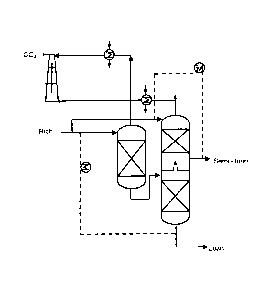
process is give by Kohl and Nielsen (1997) (Figure 1). The gas at 30 to 50 C
containing CO2
and inerts such as methane, hydrogen, or nitrogen is contacted
countercurrently in a trayed or
packed column with lean aqueous solvent entering at 30 to 50 C. The aqueous
rich solvent
containing 3 to 6 molar amine is heated by cross exchange with the hot lean
solvent. The
approach temperature for this exchanger has historically been 10 to 30 C with
a lean solution
loading of 0.01 to 0.25 moles C02/mole amine. CO is removed from the solvent
at 1.5 -2 atm
and 90-130 C in a countercurrent reboiled stripper with trays or packing.
Commercially used amines that are used by themselves in water include
monoethanolamine, diethanolamine, methyldiethanolamine, diglycolamine,
diisopropanolamine, some hindered amines, and others (Kohl and Nielsen
(1997)). These
amines are soluble or miscible with water at ambient temperature at high
concentrations that
are used in the process to maximize capacity and reduce sensible heat
requirements. Other
amines, including piperazine, are used in combination with
methyldiethanolamine and other
primary amines.
A number of mono- and polyamines, including piperazine, are identified as
potentially useful solvent components but have not been used because they are
insufficiently
soluble in water when used by themselves. Piperazine is a diamine that has
previously been
studied as a promoter for amine systems to improve kinetics. In water at 25 C,
solid
piperazine has a solubility less than 2 M, so it cannot be used in traditional
systems at
HOU03:1200893.3
CA 02765673 2011-12-15
WO 2010/134926 PCT/US2009/045075
Page 2
concentrations that give adequate CO2 capacity for good energy performance.
BASF has
disclosed the used of piperazine in combination with other amines (such as
alkanolamines) or
highly water soluble organics (such as triethyleneglycol) to promote the water
solubility of
piperazine.
It has also been claimed that number of potentially useful amines such as
piperazine
would be too volatile if used in high concentrations in aqueous solvents. The
boiling point of
piperazine (146.5 C) is lower that that of monoethanolamine (170 C), so the
use of Raoult's
law would suggest that it would have a greater volatility at the top of the
absorber.
DRAWINGS
Some specific example embodiments of the disclosure may be understood by
referring, in part, to the following description and the accompanying
drawings.
Figure 1 shows a typical flowsheet for aqueous amine absorption/stripping for
C02
removal.
Figure 2 shows an exemplary double-matrix stripper configuration.
Figure 3 shows an exemplary internal exchange stripper configuration.
Figure 4 shows an exemplary multipressure stripper configuration with a split
feed.
Figure 5 shows an exemplary flashing feed stripper configuration.
Figure 6 shows an exemplary double-matrix stripper configuration with
exemplary
operating parameters.
Figure 7 shows an exemplary internal exchange stripper configuration with
exemplary
operating parameters.
Figure 8 shows an exemplary multipressure stripper configuration with a split
feed
with exemplary operating parameters.
Figure 9 shows an exemplary flashing feed stripper configuration with
exemplary
operating parameters.
Figure 10 shows an exemplary multistage flash stripper configuration.
Figure 11 shows an exemplary generalized flowsheet for multistage stripping.
Figure 12 shows an exemplary generalized flowsheet for multistage stripping.
Figure 13 shows a solid-liquid transition temperature for aqueous PZ.
Figure 14 shows a comparison of solid solubility for aqueous PZ solutions.
HOU03:1200893.3
CA 02765673 2011-12-15
WO 2010/134926 PCT/US2009/045075
Page 3
Figure 15 shows viscosity of amine solutions at typical rich loading and 40 C.
Figure 16 shows CO2 solubility in aqueous PZ solutions ranging from 0.9 to 8 m
PZ
and from 40 to 100 C.
Figure 17 shows a comparison of mass transfer coefficients in 8 m PZ and 7 m
MEA
from 40 to 100 C.
Figure 18 shows a comparison of PZ and MEA volatility normalized to amine
concentration.
Figure 19 shows and exemplary flowsheet of a three stage flash.
Figure 20 shows equivalent work for stripping with 5 C approach and rich P*CO2
of 5
kPa for 8 m PZ.
While the present disclosure is susceptible to various modifications and
alternative
forms, specific example embodiments have been shown in the figures and are
described in
more detail below. It should be understood, however, that the description of
specific example
embodiments is not intended to limit the invention to the particular forms
disclosed, but on
the contrary, this disclosure is to cover all modifications and equivalents as
illustrated, in
part, by the appended claims.
DESCRIPTION
The present disclosure, according to certain embodiments, generally relates to
compositions, systems, and methods for the removal of acidic gas. In
particular, the present
disclosure relates to compositions, systems, and methods for the removal of
acidic gas from a
gas mixture using a solvent comprising a thermally stable amine (e.g.,
piperazine) and carbon
dioxide. Thermally stable amines generally refers to amines that are
functional at elevated
temperatures. For example, thermally stable amines may be stable up to about
130 C, 140 C,
150 C, and 170 C. Examples of suitable thermally stable amines include, but
are not limited
to, piperazine (PZ) and various substituted piperazines (e.g.,
methylpiperazine,
dimethylpiperazine, ethylpiperazine, and diethylpiperazine), morpholine, 5-
amino-l-
pentanol, 2-amino-2-methyl-l-propanol (AMP), diglycolamine (DGA ), 4-amino-l-
butanol,
3-amino-l-propanol, hydroxyethylpiperazine (HEP), 1-amino-2-propanol,
methyldiethanolamine (MDEA), 2-amino-l-propanol.
HOU03:1200893.3
CA 02765673 2011-12-15
WO 2010/134926 PCT/US2009/045075
Page 4
The present disclosure is based in part on the discovery of optimum stripper
process
configurations and operating conditions that result in unexpectedly high lean
loading of CO2.
Such process configurations may include the matrix, internal exchange,
flashing feed,
multipressure, and stripper processes described herein. Such operating
conditions may
include an unexpectedly low exchanger approach temperature. In some
embodiments, such
exchanger approach temperatures may be approximately 5 C.
The present disclosure is also based in part on the discovery that thermally
stable
amines may be less volatile in an aqueous solution than expected from Raoult's
law. In
certain embodiments, the activity coefficient of a thermally stable amine
(e.g., piperazine) at
infinite dilution in water may be about 0.05, whereas monoethanolamine (1VIEA)
has an
activity coefficient of about 0.16.
The present disclosure is also based in part on the discovery that when
thermally
stable amine solutions are loaded with about 0.1 to about 0.6 moles carbon
dioxide per amine
equivalent, the volatility of the thermally stable amine may be further
reduced. As used
herein, loading refers to moles C02/mole alkalinity where monoamine have one
mole
alkalinity per mole of amine and diamines have two moles of alkalinity per
mole amine. In
certain embodiments, the loading may be 0.25 to 0.45 moles carbon dioxide per
amine
equivalent. Such a reduction may occur at least in part because of the
formation of carbamate
ions. Such a reduction may result in the ability to produce concentrated
solutions of thermally
stable amine loaded with CO2 which have a volatility acceptable for use in the
methods of the
present disclosure.
The present disclosure is also based in part on the discovery that the total
solubility of
a solid thermally stable amine may be enhanced in solutions loaded with CO2.
In certain
embodiments, the present disclosure provides solutions comprising from about 3
in to about
20 in (moles thermally stable amine/kg water) total thermally stable amine
when said
solutions are loaded with from about 0.1 to about 0.6 moles CO2 per amine
equivalent. This
increase in solubility may be due in part to the formation of carbamate ions.
In certain
embodiments, solutions comprising from about 4 in to about 12 in (moles
thermally stable
amine/kg water) total thermally stable amine. In certain embodiments, the
solutions are
loaded with from about 0.25 to about 0.45 moles CO2 per amine equivalent.
HOU03:1200893.3
CA 02765673 2011-12-15
WO 2010/134926 PCT/US2009/045075
Page 5
The present disclosure is also based in part on the discovery that
concentrated
aqueous thermally stable amines may be more stable to oxidative and/or thermal
degradation
as compared to conventional solutions, such as MEA. In certain embodiments,
the presence
of dissolved iron may catalyze the degradation of MEA at a higher rate than
the degradation
of thermally stable amine. In certain embodiments, solutions of thermally
stable amine loaded
with CO2 may not degrade significantly even at temperatures as high as 150 C,
whereas
MEA may undergo significant degradation (up to about 50%) at 120 C. Thus, in
certain
embodiments, the present disclosure provides solutions comprising a thermally
stable amine
which may be used advantageously at higher pressures and/or temperatures. For
example, the
solutions comprising a thermally stable amine may be used at temperatures less
than 175 C.
Such an ability to operate at higher pressures and/or temperatures may, among
other things,
reduce the amount of energy necessary to perform the methods of the present
disclosure. In
certain embodiments, such a reduction of the amount of energy may range from
about 10% to
about 30%. Additionally, solutions comprising thermally stable amine may
absorb CO2 at
faster rates. In certain embodiments, the use of solutions comprising a
thermally stable amine
may result in increased in CO2 absorption rates ranging from about 20% to
about 100%. Such
increased CO2 absorption rates may, among other things, enable absorber
configurations
which require less packing and pressure drop.
When used in the methods of the present invention, the thermally stable amine
may be
recovered following absorption of CO2. In certain embodiments, such recovery
may occur
through an evaporation process using a thermal reclaimer.
In certain embodiments, the present disclosure provides a method for the
removal of
acidic gases from a gas mixture comprising contacting the gas mixture with a
solvent
comprising a thermally stable amine in an amount from about 0.1 to about 0.6
moles carbon
dioxide per amine equivalent.
While the present disclosure primarily discusses removal of C02, any acidic
gas
capable of removal by the methods of the present invention is contemplated by
the present
disclosure. Such acidic gases may include, but are not limited to, hydrogen
sulfide (1-12S) or
carbonyl sulfide (COS), CS2, and mercaptans.
The gas mixture may be any gas mixture comprising CO2 for which CO2 removal is
desired and which is compatible with (i.e. will not be adversely affected by,
or will not
HOU03:1200893.3
CA 02765673 2011-12-15
WO 2010/134926 PCT/US2009/045075
Page 6
adversely react with) the methods of the present disclosure. In certain
embodiments, the gas
mixture may comprise any gas mixture produced as the byproduct of a chemical
process.
Suitable gas mixtures may comprise one or more of natural gas and hydrogen.
Process Configurations
In certain embodiments, the present disclosure provides several process
configurations that may be useful in the methods of the present disclosure.
The choice of
process configuration may depend upon a number of factors, including, but not
limited to, the
composition of the gas mixture, the desired amount of CO2 removal, the
concentration of
thermally stable amine to be used, and resource or environmental
considerations.
One type of process configuration that may be useful in the methods of the
present
invention is a matrix stripper configuration. In certain embodiments, such a
matrix stripper
configuration may be a two-stage matrix, such as the configuration shown in
Figure 2. In
such a two-stage matrix configuration, the temperature change across the
stripper may be
reduced without the inefficiencies that may be associated with mechanical
compression. The
rich solution from the absorber may be split into two streams. The first
stream may be sent to
the first stripper at a higher pressure, which may result in a slightly
superheated feed. Heat
may be applied via reboiler steam. The lean solution from the first column may
be the
semirich feed to the middle of the second column, which may operate at a lower
pressure.
The other rich stream may be fed to the top of the second stripper. The second
column may
produce a semilean stream and a lean stream. The semilean stream may be
crossexchanged
with the rich feed to the second column, while the lean solution may be
crossexchanged with
the rich solution to the first stripper. The water vapor from the overhead of
the second
column may be condensed, and the CO2 may be sent to the first stage of the
compression
train. The water vapor in the overhead from the first column may be condensed,
and the C02
may be sent to the second stage in the compression train. The compression work
in this
configuration may be reduced due at least in part to recovery of a portion of
the C02 at a
higher pressure, which may reduce the need for compression downstream. In
certain
embodiments, the lower pressure column may be set to 160 kPa for normal
pressure
operations. In certain embodiments, the lower pressure column may be set to 30
kPa for
vacuum operations. The pressure of the higher-pressure column and the flow
into the flash
section may be optimized to minimize the total equivalent work of the system.
Even though a
HOU03:1200893.3
CA 02765673 2011-12-15
WO 2010/134926 PCT/US2009/045075
Page 7
two-stage matrix is described in the present disclosure, a three-stage matrix
may also be used
with reduced energy requirement.
Another type of process configuration that may be useful in the methods of the
present invention is multistage flash stripper configuration. In certain
embodiments, such
multistage flash strippers may be configured as a multistage flash with a
multistage
intercooled compressor as illustrated in Figure 3. Cold rich solvent from the
absorber is
heated by cross exchange with hot lean solution from the last stage. At stage
n rich solution
is heated then flashed to a lower pressure (Pn) to release CO2 with some water
vapor. The
vapor from the flash tank is combined with vapor from the next stage (n+l),
intercooled to
condense water and compressed to the pressure (Pi-1) of the previous stage.
Lean solution
from the last stage is returned to the absorber through the cross exchanger.
The process may
be optimized to select a number of stages from 1 to 6, a pressure ratio (Põ
/Põ+1) from stage to
stage of 1.2 to 10, and a heat rate at each stage from 0 to 200 kJ/mol CO2.
The temperature
of the flash tank may practically vary from 80 to 175 C. This configuration
will be especially
attractive with flash tank temperature from 120 to 170 C when used with
thermally stable
amines such as piperazine that do not degrade at the elevated temperature. The
most
attractive configuration with concentrated piperazine solution might use 3
stages, each at 140
to 150 C, with the about the same heat rate, and with approximately equal
pressure ratios.
Another type of process configuration that may be useful in the methods of the
present invention is an exchange stripper configuration. In certain
embodiments, such an
exchange stripper configuration may be an internal exchange stripper, such as
the
configuration shown in Figure 4. Among other things, this configuration
integrates the
stripping process with heat transfer. In certain embodiments, this
configuration may approach
the theoretical limit of adding and removing material and energy streams along
the entire
column. Similar configurations have been described previously by Leites et al.
and
Mitsubishi. In certain embodiments, this configuration may alleviate the
temperature drop
across the stripper by exchanging the hot lean solution with the solution in
the stripper. In
certain embodiments, the configuration may comprise a continuous heat exchange
surface,
which may allow for countercurrent heat exchange of the hot-lean solution with
the solution
passing through the stripper. In certain embodiments, a large overall heat
transfer capability
of 41.84 W/K-mol solvent per segment may be used. Such a heat transfer
capability may
HOU03:1200893.3
CA 02765673 2011-12-15
WO 2010/134926 PCT/US2009/045075
Page 8
result in a typical AT of about 1.2 K and about 3 K in the internal exchanger
for the vacuum
operation, and for operation at normal pressure, respectively.
Another type of process configuration that may be useful in the methods of the
present invention is a multipressure configuration. In certain embodiments,
such a
multipressure configuration may be a multipressure configuration with a split
feed, such as
the configuration shown in Figure 5. Similar multipressure configurations have
been
described in our previous work. In certain embodiments, this configuration may
take a 10%
split feed from the liquid flowing from the middle to the lowest pressure
level in a
multipressure stripper, and it may send this stream to an appropriate point in
the absorber. In
certain embodiments, the temperatures at the bottom of the stripper pressure
sections may be
equal, and heat may be added to each stripper pressure section to achieve
isothermal
operation in each section. Such operating conditions, among other things, may
reduce
irreversibilities and work loss. Among other things, this configuration may
take advantage of
the favorable characteristics of the multipressure configuration and the split
flow
configurations. In certain embodiments, the middle pressure may be configured
to be
approximately the geometric mean of the top pressure and the bottom pressure.
Another type of process configuration that may be useful in the methods of the
present invention is a flashing feed configuration. An example of such a
configuration is
shown in Figure 6. In certain embodiments, this configuration may comprise
special
configurations of the split flow concept described by Leites et al. and
Aroonwilas. In certain
embodiments, at least a fraction of the rich stream may be sent to the middle
of the stripper,
where, after stripping, a lean solution may exit at the bottom. The rich
solution may be cross-
exchanged with the lean solution exiting the stripper bottom. In certain
embodiments, the
vapor leaving the stripper may then be contacted with the absorber rich flow
in a five-staged
upper section where the latent heat of water vapor may be used to strip the
C02 in the `cold
feed' and a semilean stream may be produced. In certain embodiments, the
semilean product
may be cross-exchanged with the rich solution fed to the upper section. In
certain
embodiments, the reboiler duty may remain substantially unchanged, and `free
stripping' may
be achieved in the upper section. In certain embodiments, the split ratio of
the rich streams
into the middle and upper sections may be optimized to minimize equivalent
work.
HOU03:1200893.3
CA 02765673 2011-12-15
WO 2010/134926 PCT/US2009/045075
Page 9
The choice of operating conditions for each of these process configurations
may
depend upon a number of factors, including, but not limited to, the
composition of the gas
mixture, the desired amount of CO2 removal, the concentration of piperazine to
be used, and
resource or environmental considerations. Examples of suitable operating
conditions are
shown in Figures 7, 8, 9, and 10 for the double matrix, internal exchange,
multipressure with
split feed, and flashing feed stripper configurations, respectively.
Another type of process configuration that may be useful in the methods of the
present disclosure is a multistage stripper configuration and methods for
multistage stripping
that may be used at temperatures from about 120 C to about 160 C with
thermally stable
amines. The process and configuration also may be used at lower temperatures.
An example
of such a configuration is shown in Figure 11.
Figure 11 provides a generalized flowsheet example for such an embodiment. In
operation, rich solution is heated by exchange with hot lean solution. In each
of N stages the
hot lean solution, LL_,, is preheated with steam or another convenient source
of heat. The rich
solution is then distributed at the top of a gas/liquid contacting section in
the stage j stripper,
usually a packed column. The stripper is reboiled with heat provided by steam
or another
convenient source to the maximum temperature, T. The hot semilean solution,
LL, is then
sent on to stage J+1.
The vapor from the stripper at pressure, Pj, is sent to the intercooler of
stage J of the
compressor. The intercooler may be cooled by cooling water or it may serve as
a source of
useful heat. Because the high temperature stripper produces vapor as hot as
150 C, useful
heat can obtained at 150 to 80 C from both the sensible heat and latent heat
of water vapor as
the stream is cooled. The recovered heat could include boiler feedwater
preheating. The
recovered heat could also be used as in multieffect evaporation to heat a
similar generalized
multistage stripper at a lower temperature, such as 100 to 120 C. Condensed
water is
separated from the cooled vapor. The CO2 vapor is compressed to the pressure
of the
previous stage, Pi-1.
Any number of stages may be used. With only one stage, the system is very much
like a conventional simple stripper. Two or three stages may be optimal for
many
applications. After stage N the hot lean solution, LN, is cooled in the
exchanger before being
returned to the absorber.
HOU03:1200893.3
CA 02765673 2011-12-15
WO 2010/134926 PCT/US2009/045075
Page 10
In certain embodiments, elements of the generalized flowsheet described above
can be
deleted to provide simpler effective flowsheets. Usually a useful flowsheet
will use a
preheater without a reboiler or a reboiler without a preheater. One version of
a simple two
stage heated flash would delete the packing and reboiler in both stages. Both
of the stages
would operate at the same temperature, from 80 to 160 C. The preferred
temperature with an
amine that is resistant to thermal degradation, such as piperazine, is 130 to
160 C. A second
version of the two stage heated flash would delete the packing and preheater
in both stages.
Another useful two-stage configuration would delete the packing and reboiler
from stage 1
and the preheater from stage 2.
In the most likely configuration the heat for all of the preheaters and
reboilers will be
provided by steam at the same temperature. However, if steam or recovered heat
is available
at multiple temperatures the optimum configuration may used unequal
temperature in
preheaters or reboilers at the same or different stages.
In certain embodiments, the present disclosure provides a multistage stripper
configuration and methods for multistage stripping that may be used at
temperatures from
about 120 C to about 160 C with thermally stable amines with integrated heat
recovery
useing four compressor stages and two exchangers. The process and
configuration also may
be used at lower temperatures. An example of such a configuration is shown in
Figure 12. In
70 to 90% of the rich solution would be fed to Exchanger,. The heated rich
solution, L1 is
fed to Preheater, heated by steam to 150 C. Without using packing or
reboilerl, the solution
is flashed in Stripper 1 at 16 atm. The semilean solution, L2, is heated in
Preheater2 to 150 C
with steam and flashed without packing or reboiler2 in Stripper2 at 8 atm. The
hot lean
solution is returned through Exchanger, to the absorber. 10 to 30% of the rich
solution from
the absorber is fed through Exchanger2 to Preheater3 and heated by Heat
Recovery, and/or
Heat Recovery2 to 110 C. Preheater3 and Heat Recovery, may be the same heat
exchanger.
It is then flashed in Stripper3 at 4 atm without packing or reboiler3. The
semilean solution
from Stripper3 is fed through Preheater3 and heated to 110 C at 2 atm.
Preheater4 is heated by
and may be the same heat exchanger as Heat Recovery, and/or Heat Recovery2.
Preheater4
may also use heat from high temperature intercooling of other compressor
stages or from
other sources such as hot flue gas before the flue gas desulfurization system.
The Semilean
HOU03:1200893.3
CA 02765673 2011-12-15
WO 2010/134926 PCT/US2009/045075
Page 11
solution is then flashed at 2 atm in Stripper4 without packing or Reboiler4.
The hot lean
solution, L4, is returned to the absorber through Exchanger2.
Therefore, the present invention is well adapted to attain the ends and
advantages
mentioned as well as those that are inherent therein. While numerous changes
may be made
by those skilled in the art, such changes are encompassed within the spirit of
this invention as
illustrated, in part, by the appended claims.
EXAMPLES
Thermal Stability of Amines.
Example amines were screened for thermal stability based on loss of all amines
after 4
weeks at 135 C with a loading of 0.4 mol C02/mol alkalinity. In this example,
and under
these conditions, thermally stable amines were those that demonstrated less
than 37%
degradation.
Table 1: Thermal degradation screening for loss of all amines.
Amine Initial Concentration Loss of Amine
(m) (%)
Piperazine (PZ) 3.5 0
Morpholine 7 0
5-amino-1-pentanol 7 7
2-amino-2-methyl-1-propanol (AMP) 7 9
Diglycolamine (DGA ) 7 9
4-amino-1-butanol 7 10
3 -amino-1-propanol 7 13
Hydroxyethylpiperazine (HEP) 3.5 13
1 -amino-2-propanol 7 20
Methyldiethanolamine (MDEA) 8.4 (50 wt%) 33
2-amino-1-propanol 7 33
Monoethanolamine (MEA) 7 37
Aminoethylpiperazine (AEP) 2.33 37
Ethylenediamine (EDA) 3.5 45
6-amino-1-propanol 7 51
2-piperidine methanol (2PD) 7 73
Diethylenetriamine (DETA) 2.33 94
Hydroxyethylethylenediamine (HEEDA) 3.5 98
HOU03:1200893.3
CA 02765673 2011-12-15
WO 2010/134926 PCT/US2009/045075
Page 12
Carbon dioxide capture with concentrated, aqueous piperazine.
Concentrated, aqueous piperazine (PZ) was investigated as a novel amine
solvent for
carbon dioxide (C02) absorption. The CO2 absorption rate with aqueous PZ is
more than
double that of 7 m MEA and volatility at 40 C ranges from 7 to 20 ppm. Thermal
degradation is negligible in concentrated PZ solutions up to a temperature of
150 C, a
significant advantage over MEA systems. Oxidative degradation of concentrated
PZ
solutions is appreciable in the presence of copper (4 mM), but negligible in
the presence of
chromium (0.6 mM), nickel (0.25 mM), iron (0.25 mM), and vanadium (0.1 mM).
Initial
system modeling suggests that 8 m PZ will use 10 to 20% less energy than 7 m
1VIEA. The
fast kinetics and low degradation rates suggest that concentrated PZ has the
potential to be a
preferred solvent for CO2 capture.
Materials and methods
Solution preparation. Aqueous piperazine solutions were created by heating
anhydrous piperazine (99% pure, Fluka) with water until the solid crystals
melted into a
solution. The warm solution was transferred to a glass cylinder with a CO2 gas
sparger and
the cylinder was placed on a scale. The scale was used to gravimetrically add
CO2 to achieve
the desired loading.
CO2 loading through total inorganic carbon (TIC). The concentration of CO2 in
solution was determined by total inorganic carbon analysis (Hilliard, 2008).
The sample is
diluted and then acidified in 30 wt% phosphoric acid to release aqueous C02,
carbamate, and
bicarbonate species as gaseous CO2. The CO2 is carried in a nitrogen stream to
an infrared
analyzer which detects and records changes in voltage. The resulting voltage
peaks are
integrated and correlated to CO2 concentrations using a 1000 ppm inorganic
carbon standard
made from a mixture of potassium carbonate and potassium bicarbonate. CO2
loading is
reported as moles CO2 per mole alkalinity or moles CO2 per equivalence of PZ,
where two
moles of alkalinity per mole PZ is the conversion factor.
Amine titration. The concentration of piperazine in solution was determined
using
acid titration (Hilliard, 2008). An automatic Titrando series titrator with
automatic
equivalence point detection was used (Metrohm, USA). A 300X diluted sample was
titrated
with 0.1 N H2SO4 to a pH of 2.4. The amount of acid needed to reach the
equivalence point
at a pH of 3.9 was used to calculate the total amine concentration in
solution. This
HOU03:1200893.3
CA 02765673 2011-12-15
WO 2010/134926 PCT/US2009/045075
Page 13
equivalence point represents the addition of two protons to the PZ molecule
creating a
diprotonated PZ molecule. Additional equivalence points seen prior to 3.9 were
not used in
the analysis.
Viscosity measurements. Viscosity was measured using a Physica MCR 300 cone
and
plate rheometer (Anton Paar GmbH, Graz, Austria). The apparatus allows for
precise
temperature control for measuring viscosity at temperatures ranging from 20 to
70 C. To
determine viscosity, the angular speed of the top disk (cone) is increased
from 100 to 1000 s-1
over a period of 100 seconds and the shear stress exerted by the solution is
measured every
seconds. Reported viscosities are averages of these 10 individual
measurements.
10 Oxidative degradation. Oxidative degradation experiments were performed in
a low
gas flow agitated reactor with 100 mL/min of a saturated 98%/2% 02/CO2 gas
mixture fed
into the headspace (Sexton, 2008). The reactor is a 500-mL jacketed reactor is
filled with
350 mL of solvent. The jacket contains circulated water maintained at 55 C.
The reactor is
agitated at 1400 rpm to increase the mass transfer of oxygen into the
solution. The reactor is
operated continuously for 3-5 weeks, depending on the experiment. Liquid
samples are taken
every two days and water is added to maintain the water balance on the reactor
contents. The
liquid samples were analyzed for PZ concentration, CO2 loading, and
degradation products
by acid titration, TIC, and cation and anion chromatography, respectively.
Vapor-liquid equilibrium. CO2 solubility and amine volatility were measured in
a
batch equilibrium cell with gas recycle through a hot gas FTIR (Hilliard,
2008). The cell was
a jacketed, glass reactor where temperature is controlled within 1 C. The
inlet gas is sparged
from the bottom of the reactor and there is additional mechanical agitation to
enhance mass
transfer. The gas in the headspace of the reactor is continuously sampled by
an FT-IR. The
gas leaves the reactor and passes through a mist eliminator and into a sample
line heated to
180 C. The heated gas stream is then analyzed by the multi-component FTIR
analyzer and
recycled to the reactor as the inlet gas stream.
Thermal degradation. Thermal bombs were constructed from 1/4 or 3/8-inch
stainless
steel tubing with two Swagelok end caps (Davis, 2008). Bombs were filled with
2 or 10 mL
of PZ solution, sealed, and placed in forced convention ovens at multiple
different
temperatures. Individual bombs were removed from the ovens each week and the
contents
were analyzed for degradation products, remaining amine concentration, and CO2
loading.
HOU03:1200893.3
CA 02765673 2011-12-15
WO 2010/134926 PCT/US2009/045075
Page 14
Amine losses are reported as the percent of amine lost compared to the initial
amine
concentration as analyzed using cation chromatography.
Wetted-wall column operation. The wetted wall column counter-currently
contacts an
aqueous piperazine solution with a saturated N2/CO2 stream on the surface of a
stainless steel
rod with a known surface area (Cullinane and Rochelle, 2006; Dugas, 2008). The
wetted
wall column can either perform absorption or desorption of CO2 depending on
the inlet CO2
partial pressure of gas phase. By bracketing CO2 partial pressures that result
in absorption
and desorption, the equilibrium partial pressure of the solution can be
determined.
The gas flow rate entering the wetted wall column is controlled via mass flow
controllers. Inlet and outlet CO2 concentrations are measured by Horiba CO2
analyzers. As
Equation 1 shows, the calculated CO2 flux divided by the CO2 partial pressure
driving force
provides an overall mass transfer coefficient for the experiment (KG). The
overall mass
transfer coefficient is related to the liquid and gas phase mass transfer
coefficients via a series
resistance relationship shown in Equation 2.
Flux = KG (PC02,bulk - P*C02) Eqn. 1
- T - Eqn. 2
I$ k, kQ
The gas phase mass transfer coefficient, kg, is correlated to experimental
conditions
and is a strong function of the geometry of the apparatus. The liquid film
mass transfer
coefficient, kg', quantifies how fast the solution will absorb or desorb CO2.
Results.
Solid solubility. The solid solubility of PZ was studied over a range of PZ
concentration, CO2 loading, and temperature. Solutions were prepared to cover
the desired
solution properties and were allowed to equilibrate at each condition with
stirring before
solubility observations were made. The transition temperature of 8 and 10 in
PZ solutions
over a range of CO2 loading is shown in Figure 13. The transition temperature
is the
temperature at which a liquid solution will first precipitate when cooled
slowly. The
approximate temperature ramp for all transitions was 1 C every 5 minutes. The
two dashed
lines at rich loadings in Figure 13 represent soluble PZ solutions indicating
that the solubility
envelope extends at least this far. The transition temperature of unloaded PZ
solutions
HOU03:1200893.3
CA 02765673 2011-12-15
WO 2010/134926 PCT/US2009/045075
Page 15
ranging from 1.0 to 40 m PZ is shown in Figure 14 (The Dow Chemical Company,
2001;
Bishnoi, 2000; Hilliard, 2008).
The data from this study shows a eutectic point around 60 wt% PZ that was
observed
in the other data sources shown as well. For 8 m PZ, a CO2 loading of
approximately 0.25
mole CO2 per mole of alkalinity is required to maintain a liquid solution
without precipitation
at room temperature (20 C). In addition, the solubility of anhydrous PZ at 20
C is 14 wt%
PZ, which corresponds to 1.9 m PZ.
Viscosity. The viscosity of aqueous PZ solutions has been measured from 0.20
to 0.45
mole C02 per mole alkalinity, 2 m PZ to 20 m PZ, and 25 C to 60 C. The
viscosity of 8 and
10 m PZ is compared with other amines in Figure 15 (Huntsman Chemical, 2005;
Closmann,
2008). The amine concentration is plotted in units of moles alkalinity per
kilogram of water
in order to compare mono- and diamines on a similar basis. All of the
viscosities shown in
Figure 15 are at 40 C and at the rich loading of the system (0.3 mole C02 per
mole alkalinity
for MDEA and MDEA/PZ blend; 0.4 mole CO2 per mole alkalinity for PZ and DGA;
0.5
mole C02 per mole alkalinity for MEA).
Comparison of the viscosity on this basis shows how the amine basic group
affects
overall viscosity. As the concentration of basic groups increases in a
molecule, the viscosity
increases in a linear direction. The viscosity of 8 m PZ is higher than that
of 7 m 1VIEA, but
as compared to 60 wt % DGA , the viscosity of PZ is lower for a higher
alkalinity.
Therefore, PZ has the advantage of having two amine functional groups without
suffering an
increase in viscosity over DGA . DGA solutions at 60 wt % are successfully
used in
natural gas treating (Al-Juaied, 2004).
Oxidative degradation. Heavy metals are known to catalyze the oxidative
degradation
of amines (Goff and Rochelle, 2004). The results of oxidative degradation of
concentrated
PZ in the presence of several dissolved metals are shown in Table 1. The
experiments
simulated four scenarios: (1) leaching of stainless steel metals (iron,
chromium, and nickel),
(2) addition of a copper-based corrosion inhibitor, (3) addition of a vanadium-
based corrosion
inhibitor (low concentration), and (4) addition of a copper-based corrosion
inhibitor and
proprietary inhibitor "A".
Oxidative degradation of concentrated PZ was found to be four times slower
than that
of WA in the presence of stainless steel metals (Fe2+, Cr3+, and Ni2+) and a
low
HOU03:1200893.3
CA 02765673 2011-12-15
WO 2010/134926 PCT/US2009/045075
Page 16
concentration of vanadium. As with 1VIEA solutions, PZ was determined to be
highly
susceptible to oxidative degradation in the presence of Cu2+ (Goff and
Rochelle, 2006). The
primary degradation products were found to be ethylenediamine (EDA), formate,
oxalate, and
N-formylpiperazine, the amide of formate and PZ (denoted as Formamide in the
table). The
N-formylpiperazine concentration was not measured directly, but inferred from
formate
production through the basic reversal of the N-formylpiperazine formation
reaction. Also, as
with WA, Inhibitor "A" was able to vastly reduce this degradation to levels
comparable
with the stainless steel and vanadium cases (Goff and Rochelle, 2006).
Table 1: Oxidative Degradation of PZ and WA at 55 C (100 ml per min of 98%
02/2%
C02, 350 mL solution)
Case Solution Additives Rate of Formation (mM/hr)
(m) (mM) Formate Formamide EDA Amine
- 7 MEA 1.0 Fe 0.29 0.35 - -3.8
1 10 PZ 0.6 Fe2+, 0.25 Cr3+, 0.25 Ni2+ 0.005 0.007 0 -1.1
2 10 PZ 4.0 Cu2+ 0.14 0.24 0.43 -3.0
3 8 PZ 0.1 Fe2+, 0.1 V4+ 0.006 0.013 0 -0.8
4 8 PZ 4.0 Cu2+, 0.1 Fe2+, 100 "A" 0.011 0.016 0.009 -1.1
Thermal degradation. Thermal degradation was investigated in PZ solutions at
slightly above stripper temperature (135 C) and much higher than stripper
temperatures
(150 C and 175 C). The thermal degradation results are shown in Table 2 and
are reported
as the percent of amine lost per week as compared with the initial amine
concentration.
Experiments ranged from 4 to 18 weeks in length.
PZ thermal degradation was determined to be negligible at 135 and 150 C as
compared to 7 m WA. At 175 C, PZ thermal degradation was observed as a loss of
32% of
the initial PZ in 4 weeks. EDA was observed as a thermal degradation product
at 175 C but
not at lower temperatures. Addition of 5.0 mM Cu2+/0.1 mM Fe2+, 5.0 mM
Cu2+/0.1 mM
Fe2+/100 mM Inhibitor "A", and 0.6 mM Cr3+/0.25 mM Fe2+/0.25 mM Ni2+ did not
affect
degradation rates at 175 C.
HOU03:1200893.3
CA 02765673 2011-12-15
WO 2010/134926 PCT/US2009/045075
Page 17
Table 2: Comparison of Thermal Degradation for PZ and MEA
Temperature Solvent Loading Amine Loss
( C) vent (mol/mol alkalinity) (% per week)
135 7 m MEA 0.4 5.3
m PZ 0.3 0.25
7 m MEA 0.4 11
150 10 m PZ 0.3 0.80
8 m PZ 0.3 0.44
175 8 m PZ 0.3 8.0
5 C02 solubility. The measured solubility of CO2 in 2 m to 8 m PZ solutions
ranging
from 40 to 100 C is in given in Figure 16 and compared to previous studies
(Dugas, 2008;
Ermatchkov et al., 2006; Hilliard, 2008). The CO2 solubility data for PZ was
regressed to
yield the solid lines shown at on the figure at the various temperatures
indicated. The
regression of the data is the equilibrium partial pressure of CO2 in terms of
temperature, T, in
10 Kelvin, CO2 loading, a, in mole CO2 per mole alkalinity, and the universal
gas constant, R, in
kJ per mole-K, as shown in Equation 3.
Lli(P,,,) 36.1
Eqn. 3
The CO2 solubility of concentrated, aqueous PZ solutions follows the trends
found
previously for lower concentration PZ solutions at 40 and 60 C. CO2 solubility
is known to
not be a strong function of amine concentration and this is confirmed for high
concentration
PZ solutions (Hilliard, 2008). At 40 C, 8 m PZ provides a working capacity of
0.73 mole per
kg (PZ+H20), which is calculated based on a change in the equilibrium C02
partial pressure
from 7.5 kPa (loading of 0.415 mole CO2 per mole alkalinity) to 0.75 kPa (0.33
mole CO2 per
mole alkalinity). For 7 m WA at 40 C, the working capacity is 0.43 mole CO2
per kg
(MEA+H20) based on a change in the equilibrium partial pressure of C02 from 5
kPa (0.53
mole CO2 per mole alkalinity) to 0.5 kPa (0.45 mole CO2 per mole alkalinity).
The selected
range of CO2 loading for the 8 m PZ solution falls within the solubility
envelope established
in Figures 13 and 14.
Kinetics of C02 absorption in PZ solutions. The kinetics of the CO2 absorption
into
concentrated aqueous PZ was studied in a wetted wall column. The measured
liquid-side
HOU03:1200893.3
CA 02765673 2011-12-15
WO 2010/134926 PCT/US2009/045075
Page 18
mass transfer coefficient based on a gas side driving force, kg', for 8 in PZ
is shown
compared to 7 in 1VIEA in Figure 17 for 40, 60, 80, and 100 C (Dugas, 2008).
The rate data at
60, 80 and 100 C are plotted as function of the equilibrium partial pressure
of CO2 of the
solution at 40 C.
As demonstrated in Figure 17, this normalized flux, kg', for 8 in PZ is 2 to 3
times
greater than for 7 in WA. For example, at 40 C and an equilibrium C02 partial
pressure of
500 Pa, the kg' for 8 in PZ and 7 in WA are 1.98 x 10⁻⁶ and 7.66 x 10⁻⁷ mol/s-
Pa-m2,
respectively. This demonstrates that the kinetic rate of concentrated PZ is
over twice as fast
as WA at 40 C. The same trend is observed for the data at 60 C. At 80 and 100
C, the
performance improvement of PZ over WA is nearly double, although not quite as
apparent
as the lower temperatures.
Volatility of PZ solutions. The volatility of PZ was measured in an
equilibrium cell
with hot gas FTIR. The volatility of 8 in PZ solutions is compared to that of
5 in PZ and 7 in
MEA in Figure 18. The volatility of each solution is normalized by the amine
concentration
for comparison purposes.
At 40 C, the normalized volatility of PZ solutions is in the same range as the
normalized volatility of WA solutions. It was anticipated that PZ would have a
higher
volatility than WA because the boiling point of PZ, 146 C, is lower than that
of WA,
170 C. However, the volatility of both 5 and 8 in PZ is slightly lower at 40
C. Modeling of
PZ systems demonstrates this effect as a greatly reduced activity coefficient
for PZ due to the
solution's non-ideality (Hilliard, 2008). At 40 C, PZ volatility varies from 7
to 20 ppm at
atmospheric pressure.
Estimated energy requirement. The thermodynamic model for PZ developed by
Hilliard (2008) was modified to represent the new data for concentrated PZ.
The stripper of a
system for C02 removal was simulated for 8 in PZ and compared with 7 in WA.
One set of
these simulations included a simple stripper with C02 compression to 15 MPa
(150 atm), a
5 C cold side temperature approach for the cross heat exchanger, and a 10 C
approach for the
reboiler. The columns were simulated using the AspenPlus RateSep tool that
calculated
heat and mass transfer rates but assumed reactions reached equilibrium. In
each simulation,
15 meters of CMR NO-2P packing and an 80% approach to flood were used.
HOU03:1200893.3
CA 02765673 2011-12-15
WO 2010/134926 PCT/US2009/045075
Page 19
A second set of simulations was performed in AspenPlus using two and three
stage
flash configurations. The flowsheet for the three stage flash is shown in
Figure 19. The two
stage flash is analogous with one less flash tank. In a multi-stage flash,
hot, rich amine
leaving the cross exchanger enters a series of flash tanks that are either
heated or adiabatic.
The figure shows the design used for these simulations, where each stage is
shown heated
with steam. In each tank, C02 flashes off and is sent to a multi-stage
compressor. A multi-
stage flash collects C02 at multiple pressure levels, therefore reducing
compression work.
There is a potential opportunity for heat recovery from the water vapor
leaving each of the
flash tanks. One option is to use this heat to pre-heat the boiler feed water
used in the coal-
fired power plant (Gibbins and Crane, 2004).
The rich stream for each case assumed a P*C02 of 5 kPa at the absorber
temperature
of 40 C. Equivalent work, Weq, is calculated as shown in equation 3 using the
C02 removal
rate, nCO2, stripper reboiler duty, Q, reboiler temperature, Treboiler,
cooling water
temperature of 40 C, Tsink, total pumping work, Wpump, and total CO2
compression work to
achieve 15 MPa, Wc mp.
7~ Egn.3
Each system was optimized for lean loading and the equivalent work as a
function of lean
loading as shown in Figure 20. The baseline system, 7 m MEA, had an equivalent
work of
40.3 kJ per mole C02. The 8 m PZ simple stripper system had a minimum
equivalent work
of 36.5 kJ per mole C02. The two and three stage flashes using 8 m PZ had
minimum
equivalent works of 34.1 and 33.8 kJ per mole C02, respectively.
The increased capacity of PZ improved its performance in all cases over the
baseline
7 m WA case, despite a lower AHabs. For the PZ cases, the lowest equivalent
work was
achieved in the three stage flash simulation, demonstrating the advantages of
multistage
compression and heat recovery that can be achieved using a solvent that is
resistant to
thermal degradation.
Degradation of Concentrated Piperazine in Pilot Plant.
A long term thermal degradation experiment demonstrated the thermal resistance
of
concentrated PZ. After 18 weeks at 150 C, only 8.0% of the initial PZ was
lost. This
HOU03:1200893.3
CA 02765673 2011-12-15
WO 2010/134926 PCT/US2009/045075
Page 20
amounts to a loss of only 0.44% of the original PZ per week. The most
prevalent degradation
products were EDA (1.2 mM/wk), formate (0.9 mM /wk), and N-formyl amides (2.3
mM/wk). As demonstrated by the low weekly loss of PZ, 8 m PZ has enhanced
resistance to
thermal degradation as compared with 1VIEA, DGA, and MDEA/PZ blends.
Table 3: Comparison of Thermal Degradation Rates of Amines
Temperature Solvent System CO2 Loading Amine Loss
( C) (mol/mol alkalinity) (/o/week)
7 m MEA 0.4 6.0
135 7 m MDEA/2 m PZ 0.1 3.7
7 m DGA 0.4 1.8
m PZ 0.3 0.3
7 m MEA 0.4 11
150 7 m MDEA/2 m PZ 0.1 6.4
10 m PZ 0.3 0.80
8 m PZ 0.3 0.44
175 8 m PZ 0.3 8.0
Conclusions.
Concentrated, aqueous solutions of PZ have shown promise for improved solvent
performance in absorption/stripping systems used for CO2 capture. For 8 m PZ,
a CO2
10 loading of approximately 0.25 mole CO2 per mole alkalinity is required to
maintain a liquid
solution without precipitation at room temperature (20 C). Additionally, the
solubility of PZ
at 20 C is approximately 14 wt% PZ, or 1.9 m PZ. The volatility of 8 m PZ
systems was
found to be between 7.3 and 20.2 ppm PZ at 40 C, which is comparable to 7 m WA
solutions.
Oxidative degradation of concentrated PZ has been shown to be four times
slower
than 7 m MEA in the presence of the combination of Fe2+/Cr3+/Ni2+ and
Fe2+/V4+. In the
presence of copper-based corrosion inhibitors, oxidative degradation is an
issue but can be
drastically reduced with the use of Inhibitor "A". Concentrated PZ is
resistant to thermal
degradation up to 150 C but does degrade at 175 C, losing 32% of the PZ over 4
weeks. The
resistance of PZ to thermal degradation allows for the possibility of higher
pressure strippers
to improve energy performance.
Kinetic measurements have shown that the rate of CO2 absorption into 8 m PZ is
more than twice that of 7 m WA at 40 C and nearly double at 60 C. The working
capacity
HOU03:1200893.3
CA 02765673 2011-12-15
WO 2010/134926 PCT/US2009/045075
Page 21
of an 8 m PZ solution is 0.73 mole CO2 per kg (PZ + H20), nearly double that
of 7 m MEA.
Initial modeling of a simple stripper section indicate that the equivalent
work required for
stripping of an 8 m PZ solution will be approximately 10-20% lower than that
of 7 m MEA.
The use of a multi-stage flash also has demonstrated advantages for a high
temperature
operation that is feasible with the thermally stable 8 m PZ solution.
The rapid rate of CO2 absorption, low degradation rate, and low predicted
equivalent
work indicate that 8 m PZ solutions are an attractive option for CO2 capture
in
absorption/stripping systems.
Therefore, the present invention is well adapted to attain the ends and
advantages
mentioned as well as those that are inherent therein. While numerous changes
may be made
by those skilled in the art, such changes are encompassed within the spirit of
this invention as
illustrated, in part, by the appended claims.
References:
S. Bishnoi, Carbon Dioxide Absorption and Solution Equilibrium in Piperazine
Activated Methyldiethanolamine. The University of Texas at Austin, Austin, TX,
2000.
M.D. Hilliard, A Predictive Thermodynamic Model for an Aqueous Blend of
Potassium Carbonate, Piperazine, and Monoethanolamine for Carbon Dioxide
Capture from
Flue Gas. The University of Texas at Austin, Austin, TX, 2008.
J.T. Cullinane and G.T. Rochelle, "Thermodynamics of aqueous potassium
carbonate,
piperazine, and carbon dioxide." Fluid Phase Equilibria. 227(2) (2005) 197-
213.
A. Sexton, "Catalysts and inhibitors for MEA oxidation." Presentation at GHGT-
9,
Washington D.C., 2008.
J. Davis, "Thermal degradation of monoethanolamine at stripper conditions."
Presentation at GHGT-9, Washington D.C., 2008.
R. Dugas, "Absorption and desorption rates of carbon dioxide with
monoethanolamine and piperazine." Presentation at GHGT-9, Washington D.C.,
2008.
Brochure, Dow Chemical Company, Ethyleneamines; August, 2001 p 48.
Brochure, Diglycolamine Agent - Product Information, Diglycolamine Agent -
Product Information; 2005 p 60.
F. Closmann, "MDEA/piperazine as a solvent for CO2 capture." Presentation at
GHGT-9, Washington D.C., 2008.
HOU03:1200893.3
CA 02765673 2011-12-15
WO 2010/134926 PCT/US2009/045075
Page 22
M.A. Al-Juaied, Carbon Dioxide Removal from Natural Gas by Membranes in the
Presence of Heavy Hydrocarbons and by Aqueous Diglycolamine%Morpholine. The
University of Texas at Austin, Austin, TX, 2002.
G.S. Goff and G.T. Rochelle, "Monoethanolamine degradation: 02 mass transfer
effects under CO2 capture conditions." Ind. Eng. Chem. Res. 43(20) (2004) 6400-
6408.
G.S. Goff and G.T. Rochelle, "Oxidation inhibitors for copper and iron
catalyzed
degradation of monoethanolamine in CO2 capture processes." Ind. Eng. Chem.
Res. 45(8)
(2006) 2513-2521.
V. Ermatchkov, A.P.S. Kamps, D. Speyer, and G. Maurer, "Solubility of carbon
dioxide in aqueous solutions of piperazine in the low gas loading region." J
Chem. Eng. Data
51(5) (2006) 1788-1796.
HOU03:1200893.3