Language selection

Search

Patent 2766604 Summary

Third-party information liability

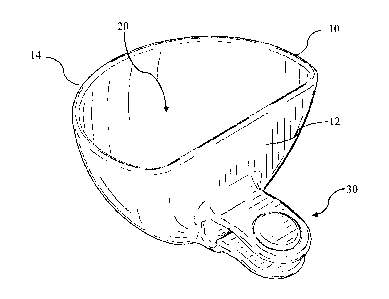
Some of the information on this Web page has been provided by external sources. The Government of Canada is not responsible for the accuracy, reliability or currency of the information supplied by external sources. Users wishing to rely upon this information should consult directly with the source of the information. Content provided by external sources is not subject to official languages, privacy and accessibility requirements.

Claims and Abstract availability

Any discrepancies in the text and image of the Claims and Abstract are due to differing posting times. Text of the Claims and Abstract are posted:

  • At the time the application is open to public inspection;
  • At the time of issue of the patent (grant).
(12) Patent Application: (11) CA 2766604
(54) English Title: DIP CLIP
(54) French Title: PORTE-TREMPETTE A FIXATION
Status: Deemed Abandoned and Beyond the Period of Reinstatement - Pending Response to Notice of Disregarded Communication
Bibliographic Data
(51) International Patent Classification (IPC):
  • A47G 19/30 (2006.01)
  • A47G 19/06 (2006.01)
  • A47G 21/14 (2006.01)
(72) Inventors :
  • MYOUNG, SUL GI (United States of America)
  • MADDEN, JEFFERY DAVID (Canada)
(73) Owners :
  • PROGRESSIVE INTERNATIONAL CORPORATION
(71) Applicants :
  • PROGRESSIVE INTERNATIONAL CORPORATION (United States of America)
(74) Agent: SMART & BIGGAR LP
(74) Associate agent:
(45) Issued:
(22) Filed Date: 2012-02-02
(41) Open to Public Inspection: 2012-08-08
Examination requested: 2016-12-13
Availability of licence: N/A
Dedicated to the Public: N/A
(25) Language of filing: English

Patent Cooperation Treaty (PCT): No

(30) Application Priority Data:
Application No. Country/Territory Date
13/359,243 (United States of America) 2012-01-26
61/440,535 (United States of America) 2011-02-08

Abstracts

English Abstract


A dip clip includes a container portion and a clip portion. The container
portion is
configured to hold a desired quantity of a dip such as salsa, dressings, or
other such food
items. The clip portion is configured to provide a point of attachment so that
the container
portion may be removably attached to a plate or other dish


Claims

Note: Claims are shown in the official language in which they were submitted.

THE EMBODIMENTS OF THE INVENTION IN WHICH AN EXCLUSIVE
PROPERTY OR PRIVILEGE IS CLAIMED ARE DEFINED AS FOLLOWS:
1. A dip clip, comprising:
a container having an upper rim, a base, and a sidewall extending from the
base to the
rim to define an interior space; and
a clip attached to the container and extending laterally away from the base,
the clip
being removably attachable to a plate.
2. The dip clip of claim 1, wherein the base of the container defines a base
plane, and
further wherein the clip is oriented to receive a rim of a plate at an angle
inclined with
respect to the base plane.
3. The dip clip of claim 2, wherein the angle is less than about 30 degrees.
4. The dip clip of claim 1, wherein the clip comprises an upper arm and a
lower arm, each
of the upper arm and lower arm being integrally formed with the container.
5. The dip clip of claim 4, wherein at least one of the upper arm and the
lower arm is
movable apart from the other one of the upper arm or the lower arm to receive
a rim of a
plate.
-8-

6. The dip clip of claim 4, wherein the lower arm comprises a first portion
adjacent the
container, a lower angled portion, and an intermediate portion between the
first portion
and the lower angled portion.
7. The dip clip of claim 6, wherein the first portion of the lower arm
comprises a downward
recessed channel.
8. The dip clip of claim 6, wherein the lower angled portion is inclined
downward,
relatively in the direction of the base.
9. The dip clip of claim 4, wherein the upper arm further comprises a lateral
portion and an
upper angled portion, the upper angled portion being angled downward,
relatively in the
direction of the base.
10. The dip clip of claim 4, wherein one of the upper arm and the lower arm
comprises a
resilient pad positioned in the space defined between the upper arm and the
lower arm.
11. A method for serving a food item, comprising:
providing a dip clip in accordance with claim 1;
attaching the dip clip to a rim of a plate; and
filling the container of the dip clip with the food item.
-9-

12. The method of claim 11, wherein the step of filling the container is
performed before the
step of attaching the dip clip.
13. A dip clip, comprising:
a container having an upper rim, a base, and a sidewall extending from the
base to the
rim to define an interior space; and
a clip attached to the container and extending laterally away from the base,
the clip
being removably attachable to a plate, the clip further having an upper arm
and a lower
arm, each of the upper arm and the lower arm having a first lateral portion
extending
laterally away from the container, and a second angled portion inclined
downward from
the lateral portion.
14. The dip clip of claim 13, wherein one of the upper arm and the lower arm
comprises a
resilient pad positioned in the space defined between the upper arm and the
lower arm.
-10-

Description

Note: Descriptions are shown in the official language in which they were submitted.


CA 02766604 2012-02-02
DIP CLIP
FIELD OF THE INVENTION
[0001] This invention generally relates to bowls or other containers for
holding salsa
or other dips.
SUMMARY OF THE INVENTION
[0002] A dip clip in accordance with the present invention includes a
container
portion and a clip portion. The container portion is configured to hold a
desired quantity of a
dip such as salsa, dressings, or other such food items. The clip portion is
configured to
provide a point of attachment so that the container portion may be removably
attached to a
plate or other dish.
[0003] In accordance with preferred aspects of the invention as described in
more
detail below, the clip portion may include upper and lower arms that are
separable to receive
a portion of a plate, frictionally securing the plate between the upper and
lower arms to hold
the dip clip to the plate or other dish.
-1-

CA 02766604 2012-02-02
BRIEF DESCRIPTION OF THE DRAWINGS
[0004] Figure 1 is a perspective view of a preferred dip clip.
[0005] Figure 2 is a side view of a preferred dip clip.
[0006] Figure 3 is a side view of a preferred dip clip.
DETAILED DESCRIPTION OF THE PREFERRED EMBODIMENT
[0007] A preferred dip clip in accordance with this invention includes a
container or
bowl 10 forming an interior space 20. The container portion may have any size
or shape,
though in a preferred example the container has a capacity of about 1/3 cup to
V2 cup. This
size is suitable as an individual portion size, ideal for use when attached to
an individual-
sized plate 70. In other versions the container may be larger or smaller, as
desired for
particular uses.
[0008] As viewed from the top or a side, the bowl portion preferably is formed
with a
substantially flat side 12 and an opposing arched side 14. The flat side is
intended to be
positionable adjacent an edge of a plate or platter, and is shaped to have a
substantially flat
side so that it does not extend significantly over the surface area defined by
the plate or
platter. Thus, the flat side is designed to be positioned generally
tangentially to an edge of a
circular plate or platter. The opposite arched side preferably bows outwardly
in order to
create a suitably sized interior space for receiving the dip or other food
item. In other
versions, the rim and bowl of the container portion may have a different
shape, such as a
cubic rectangle or an entirely round shape instead of flat truncated
hemisphere.
-2-

CA 02766604 2012-02-02
[00091 The clip portion 30 extends laterally away from the flat side 12 of the
bowl,
preferably from a position at the bottom of the container portion. In the
preferred version, the
clip portion comprises an upper arm 40 and a lower arm 50, with the upper and
lower arms
being positioned adjacent one another and configured to receive an edge of a
plate or platter
between them. Ideally, at least one of the upper or lower arms is sufficiently
flexible to move
apart from the other arm to receive an edge of the plate and to impart a
gripping force on the
edge of the plate to hold the dip clip to the plate. In other versions both of
the upper and
lower arms have a degree of flexibility to allow the clip to be removably
secured to the plate.
[00101 The lower arm 50 extends laterally away from the lower portion of the
container portion, and in the illustrated version it extends laterally away
from the lower
portion of the flat side of the container portion. Accordingly, a first
portion 55 of the lower
arm defines a bottom surface that is substantially co-planar with the lower
surface of the
container portion of the dip clip.
[00111 The upper surface 51 of the first portion 55 of the lower arm is formed
with a
channel that is sized and configured to receive a rim of a plate. Thus, the
channel is
preferably rounded in cross-section. In addition to being shaped to receive a
portion of a rim
of a plate, the channel may be configured to enable the lower arm to pivot at
the point of the
channel, depending on the thickness of the material used at the location of
the channel. The
first portion of the lower arm transitions to an intermediate portion 52 that
extends laterally
-3-

CA 02766604 2012-02-02
away from the container and is nearly or substantially parallel with the lower
surface of the
bowl.
[0012] Finally, the lower arm includes an angled portion 53 adjacent the
intermediate
portion. The angled portion is angled downward somewhat with respect to the
axis defined
by the intermediate portion. In one version, the angled portion is oriented
downwardly at an
angle of about 30 degrees with respect to the intermediate portion. As
illustrated, the length
of the angled portion is approximately equal to the length of the combined
first portion and
intermediate portion. In this regard, the illustrated examples are intended to
be drawn to
scale, though in other versions the dimensional relationships may be altered.
[0013] The upper arm 40 includes a first lateral portion 41 and a second
angled
portion 42. The first lateral portion extends laterally away from the
container portion and is
attached to the flat side of the container portion at a position above that of
the lower arm. The
upper and lower arms are spaced apart from one another by a distance
sufficient to snugly
receive a rim of a plate or platter between them.
[0014] The angled portion 42 of the upper arm is angled downward with respect
to
the axis defined by the upper, such that the angled portion of the upper arm
is generally
parallel to the angled portion of the lower arm. In a preferred version,
however, the angles of
the upper and lower portions may be slightly offset from one another such that
the two
portions are not quite parallel. In such a version, the tips of the upper and
lower angled
-4-

CA 02766604 2012-02-02
portions are closer to one another than any other position along either
portion. As illustrated,
the upper arm and lower arm are substantially the same length as one another.
[00151 The upper arm may include a resilient pad 60. The resilient pad in the
preferred example is formed from silicone or any other substantially resilient
material. In one
version it is formed as a generally cylindrical shape having an intermediate
channel. The
upper arm is formed with a round hole shaped to be received within the channel
of the
resilient pad to secure the pad to the upper arm. In other versions, the
resilient pad may be
molded, glued, or otherwise attached to the arm. Likewise, the resilient pad
need not extend
through the upper arm, but may alternatively be attached to a lower surface of
the upper arm
or may be integrally formed from the same material used for the upper arm. In
this latter
version, the pad may not be resilient if the material used for the upper arm
is not resilient.
Still further, the resilient pad may be formed on the lower arm rather than
the upper arm.
[00161 In the preferred version as illustrated, the resilient pad forms a
surface that
extends between the angled portions of the upper and lower arms. By extending
into the
space between the arms, the resilient pad provides greater force against a
portion of a plate
that is positioned between the upper and lower arms. In addition, when the pad
is formed
from a resilient material it is at least somewhat compressible, thereby
allowing for more
flexure for receiving a rim of a plate while providing sufficient force to
hold the clip to the
plate. Likewise, the pad, together with the resilience of the arms, allows the
clip to
accommodate a variety of plates having differing thicknesses.
-5-

CA 02766604 2012-02-02
[0017] In some versions of the invention, the arms are substantially rigid and
the clip
relies primarily on the resilient qualities of the pad to retain and release a
plate from the clip.
[0018] In use, the clip portion is placed adjacent a rim of a plate and the
plate is
pushed into the space defined between the upper and lower arms. The resilient
nature of the
arms or the resilient pad allows them to be forced apart somewhat to snugly
receive the rim
of the plate. Once in position, the frictional force urging the arms toward
one another (and/or
the natural return force of the resilient pad) holds the clip portion in place
about an edge of
the rim of the plate. The bowl portion may be filled with salsa or another
dip, thereby
providing a vessel for holding dip along an edge of the plate.
[0019] The angled orientation of the clip with respect to the container is
further
illustrated in Figure 3. As shown, the base of the container forms a planar
floor in the
preferred example, substantially along a plane H in Figure 3. An upper surface
of the lower
arm of the clip is inclined along line I, which as explained above is
preferably about
30 degrees (indicated by angle A) of incline with respect to the horizontal
axis H. Because a
peripheral rim of a plate is typically tipped upward, this angled orientation
of the clip allows
the plate to be received at the angle of the plate rim while maintaining the
container in a
horizontal configuration. Likewise, the configuration of the clip with respect
to the base of
the container ensures that the base of the container remains above a
horizontal surface on
which the plate is resting when the clip is attached to the plate.
-6-

CA 02766604 2012-02-02
[00201 While the preferred embodiment of the invention has been illustrated
and
described, as noted above, many changes can be made without departing from the
spirit and
scope of the invention. Accordingly, the scope of the invention is not limited
by the
disclosure of the preferred embodiment. Instead, the invention should be
determined entirely
by reference to the claims that follow.
-7-

Representative Drawing
A single figure which represents the drawing illustrating the invention.
Administrative Status

2024-08-01:As part of the Next Generation Patents (NGP) transition, the Canadian Patents Database (CPD) now contains a more detailed Event History, which replicates the Event Log of our new back-office solution.

Please note that "Inactive:" events refers to events no longer in use in our new back-office solution.

For a clearer understanding of the status of the application/patent presented on this page, the site Disclaimer , as well as the definitions for Patent , Event History , Maintenance Fee  and Payment History  should be consulted.

Event History

Description Date
Time Limit for Reversal Expired 2020-02-04
Application Not Reinstated by Deadline 2020-02-04
Letter Sent 2020-02-03
Common Representative Appointed 2019-10-30
Deemed Abandoned - Failure to Respond to Maintenance Fee Notice 2019-02-04
Amendment Received - Voluntary Amendment 2018-12-20
Inactive: S.30(2) Rules - Examiner requisition 2018-08-23
Inactive: Q2 failed 2018-08-22
Amendment Received - Voluntary Amendment 2018-05-14
Maintenance Request Received 2018-01-09
Inactive: S.30(2) Rules - Examiner requisition 2017-11-14
Inactive: Report - No QC 2017-11-09
Letter Sent 2016-12-20
Request for Examination Requirements Determined Compliant 2016-12-13
All Requirements for Examination Determined Compliant 2016-12-13
Request for Examination Received 2016-12-13
Change of Address or Method of Correspondence Request Received 2015-02-17
Inactive: Cover page published 2012-08-09
Application Published (Open to Public Inspection) 2012-08-08
Inactive: IPC assigned 2012-07-19
Inactive: First IPC assigned 2012-07-19
Inactive: IPC assigned 2012-07-19
Letter Sent 2012-02-21
Inactive: Filing certificate - No RFE (English) 2012-02-16
Filing Requirements Determined Compliant 2012-02-16
Application Received - Regular National 2012-02-15

Abandonment History

Abandonment Date Reason Reinstatement Date
2019-02-04

Maintenance Fee

The last payment was received on 2018-01-09

Note : If the full payment has not been received on or before the date indicated, a further fee may be required which may be one of the following

  • the reinstatement fee;
  • the late payment fee; or
  • additional fee to reverse deemed expiry.

Patent fees are adjusted on the 1st of January every year. The amounts above are the current amounts if received by December 31 of the current year.
Please refer to the CIPO Patent Fees web page to see all current fee amounts.

Fee History

Fee Type Anniversary Year Due Date Paid Date
Registration of a document 2012-02-02
Application fee - standard 2012-02-02
MF (application, 2nd anniv.) - standard 02 2014-02-03 2014-01-24
MF (application, 3rd anniv.) - standard 03 2015-02-02 2015-01-21
MF (application, 4th anniv.) - standard 04 2016-02-02 2015-12-07
Request for examination - standard 2016-12-13
MF (application, 5th anniv.) - standard 05 2017-02-02 2016-12-13
MF (application, 6th anniv.) - standard 06 2018-02-02 2018-01-09
Owners on Record

Note: Records showing the ownership history in alphabetical order.

Current Owners on Record
PROGRESSIVE INTERNATIONAL CORPORATION
Past Owners on Record
JEFFERY DAVID MADDEN
SUL GI MYOUNG
Past Owners that do not appear in the "Owners on Record" listing will appear in other documentation within the application.
Documents

To view selected files, please enter reCAPTCHA code :


To view images, click a link in the Document Description column. To download the documents, select one or more checkboxes in the first column and then click the "Download Selected in PDF format (Zip Archive)" or the "Download Selected as Single PDF" button.

List of published and non-published patent-specific documents on the CPD .

If you have any difficulty accessing content, you can call the Client Service Centre at 1-866-997-1936 or send them an e-mail at CIPO Client Service Centre.


Document
Description 
Date
(yyyy-mm-dd) 
Number of pages   Size of Image (KB) 
Description 2012-02-01 7 215
Claims 2012-02-01 3 68
Abstract 2012-02-01 1 9
Drawings 2012-02-01 3 34
Representative drawing 2012-08-07 1 13
Description 2018-05-13 8 247
Claims 2018-05-13 3 72
Claims 2018-12-19 3 67
Filing Certificate (English) 2012-02-15 1 167
Courtesy - Certificate of registration (related document(s)) 2012-02-20 1 102
Reminder of maintenance fee due 2013-10-02 1 112
Reminder - Request for Examination 2016-10-03 1 123
Acknowledgement of Request for Examination 2016-12-19 1 174
Courtesy - Abandonment Letter (Maintenance Fee) 2019-03-17 1 173
Commissioner's Notice - Maintenance Fee for a Patent Application Not Paid 2020-03-15 1 535
Examiner Requisition 2018-08-22 3 178
Correspondence 2015-02-16 4 234
Request for examination 2016-12-12 2 69
Examiner Requisition 2017-11-13 6 327
Maintenance fee payment 2018-01-08 2 84
Amendment / response to report 2018-05-13 14 399
Amendment / response to report 2018-12-19 6 148