Note: Descriptions are shown in the official language in which they were submitted.
CA 02766637 2011-12-22
WO 2010/151560 PCT/US2010/039559
SYSTEM AND METHOD FOR MANAGING THERMAL
ISSUES IN ONE OR MORE INDUSTRIAL PROCESSES
RELATED APPLICATION DATA
This patent application claims priority to United States Provisional Patent
Application No. 61/219,1956, filed on June 22, 2009, entitled "System and
Method
for Managing Thermal Issues in Gas Turbine Engines," the entirety of which is
hereby incorporated by reference herein.
FIELD OF THE INVENTION
The present invention generally relates to a system that enables one to both:
(i) address various thermal management issues (e.g., inlet air cooling) in gas
turbines, gas turbine engines, industrial process equipment and/or internal
combustion engines; and (ii) yield a supercritical fluid-based heat engine. In
one
embodiment, the present invention utilizes at least one working fluid selected
from
ammonia, carbon dioxide, nitrogen, or other suitable working fluid medium. In
another embodiment, the present invention utilizes carbon dioxide or ammonia
as a
working fluid to achieve a system that enables one to address inlet cooling
issues in
a gas turbine, internal combustion engine or other industrial application
while also
yielding a supercritical fluid based heat engine as a second cycle using the
waste
heat from the gas turbine and/or internal combustion engine to create a
combined
power cycle.
BACKGROUND OF THE INVENTION
Various approaches have been suggested to address various thermal
management issues (e.g., inlet air cooling, waste heat recovery) in gas
turbines, gas
turbine engines, internal combustion engines and other industrial processes.
Such
approaches include those discussed in the report entitled Experimental and
Theoretical Investigations of New Power Cycles and Advanced Falling Film Heat
Exchangers by the U.S. Department of Energy in conjunction with the University
of
New Mexico.
In this report two new thermodynamic cycles were proposed and investigated
based on the second law of thermodynamics. Two computer programs were
developed to find effect of important system parameters on the irreversibility
1
CA 02766637 2011-12-22
WO 2010/151560 PCT/US2010/039559
distribution of all components in the cycle: (1) the first cycle was based on
a
combined triple (Brayton/Rankine/Rankine)/(Gas/steam/ammonia) cycle capable of
producing high efficiencies; and (2) the second cycle is a combined
(Brayton/Rankine)/(gas/ammonia) cycle with integrated compressor inlet air-
cooling
capable of producing high power and efficiency. The proposed cycles and the
results obtained from the second law analyses of the cycles were published in
Energy Conversion and Management and ASME proceedings (IMEC&E 2001).
Given the above, there is a need in the art for systems that are designed to
address various thermal management issues for various devices (e.g., gas
turbines,
gas turbine engines, industrial process equipment and/or internal combustion
engines). In one instance, there is a need for a system that is able to
address
various thermal management issues (e.g., inlet air cooling) in gas turbines,
gas
turbine engines, internal combustion engines and/or other industrial process
equipment.
SUMMARY OF THE INVENTION
The present invention generally relates to a system that enables one to both:
(i) address various thermal management issues (e.g., inlet air cooling) in gas
turbines, gas turbine engines, industrial process equipment and/or internal
combustion engines; and (ii) yield a supercritical fluid-based heat engine. In
one
embodiment, the present invention utilizes at least one working fluid selected
from
ammonia, carbon dioxide, nitrogen, or other suitable working fluid medium. In
another embodiment, the present invention utilizes carbon dioxide or ammonia
as a
working fluid to achieve a system that enables one to address inlet cooling
issues in
a gas turbine, internal combustion engine or other industrial application
while also
yielding a supercritical fluid based heat engine as a second cycle using the
waste
heat from the gas turbine and/or internal combustion engine to create a
combined
power cycle.
In one embodiment, the present invention relates to a system that is designed
to both achieve inlet air cooling in gas turbines, gas turbine engines,
internal
combustion engines and/or other industrial processes (e.g., gas or air
compression)
while also yielding a supercritical fluid-based heat engine as a second cycle
using
2
CA 02766637 2011-12-22
WO 2010/151560 PCT/US2010/039559
the waste heat from the gas turbine, internal combustion engine, and/or other
industrial process to create a combined power cycle as shown and described
herein.
In another embodiment, the present invention relates to a system for
temperature conditioning inlet air for a turbine comprising: at least one
turbine
having an inlet side and an outlet side; at least one air inlet heat exchanger
operatively coupled to the inlet side of the at least one turbine, wherein the
at least
one air inlet heat exchanger is designed to remove heat from inlet air being
supplied
to the inlet side of the at least one turbine and transfer such heat via a
working fluid
to a bottom loop; at least one air outlet heat exchanger operatively coupled
to the
outlet side of the at least one turbine, wherein the at least one air outlet
heat
exchanger is designed to remove heat from outlet air being generated by the at
least
one turbine and transfer such heat via a working fluid to the bottom loop;
wherein the
bottom loop is designed to utilize such transferred heat from the at least one
air inlet
heat exchanger and the at least one air outlet heat exchanger to provide
suitably
conditioned working fluid back to both the at least one air inlet heat
exchanger and
the at least one air outlet heat exchanger.
In still another embodiment, the present invention relates to a method for
temperature conditioning inlet air for a turbine, the method comprising the
steps of:
providing at least one turbine having an inlet side and an outlet side;
providing at
least one air inlet heat exchanger operatively coupled to the inlet side of
the at least
one turbine, wherein the at least one air inlet heat exchanger is designed to
remove
heat from inlet air being supplied to the inlet side of the at least one
turbine and
transfer such heat via a working fluid to a bottom loop; providing at least
one air
outlet heat exchanger operatively coupled to the outlet side of the at least
one
turbine, wherein the at least one air outlet heat exchanger is designed to
remove
heat from outlet air being generated by the at least one turbine and transfer
such
heat via a working fluid to the bottom loop; wherein the bottom loop transfers
heat
from the at least one air inlet heat exchanger and the at least one air outlet
heat
exchanger to provide suitably conditioned working fluid back to both the at
least one
air inlet heat exchanger and the at least one air outlet heat exchanger.
In still yet another embodiment, the present invention relates to a system for
temperature conditioning air comprising: at least one heat source; at least
one first
heat exchanger operatively coupled to the at least one heat source and
designed to
3
CA 02766637 2011-12-22
WO 2010/151560 PCT/US2010/039559
remove and/or utilize waste heat from the heat source to transfer such heat to
a
working fluid; at least one compressor operatively coupled via the working
fluid to the
at least one first heat exchanger, wherein the at least one compressor is
designed
receive the heat-laden working fluid generated by the at least one first heat
exchanger and to utilize, or bleed heat from, the heat laden working fluid so
as to
yield a cooled working fluid; at least one second heat exchanger operatively
coupled
to the at least one compressor, wherein the at least one second heat exchanger
is
designed to receive the cooled working fluid and to utilize the cooled working
fluid to
remove heat from, or condition the temperature of, air.
BRIEF DESCRIPTION OF THE DRAWINGS
Figure 1 is an illustration of a system in accordance with one embodiment of
the present invention;
Figure 2 is an illustration of another system in accordance with one
embodiment of the present invention;
Figure 3 is an illustration of another system in accordance with one
embodiment of the present invention;
Figure 4 is an illustration of another system in accordance with one
embodiment of the present invention; and
Figure 5 is an illustration of another system in accordance with one
embodiment of the present invention.
DETAILED DESCRIPTION OF THE INVENTION
The present invention generally relates to a system that enables one to both:
(i) address various thermal management issues (e.g., inlet air cooling) in gas
turbines, gas turbine engines, industrial process equipment and/or internal
combustion engines; and (ii) yield a supercritical fluid-based heat engine. In
one
embodiment, the present invention utilizes at least one working fluid selected
from
ammonia, carbon dioxide, nitrogen, or other suitable working fluid medium. In
another embodiment, the present invention utilizes carbon dioxide or ammonia
as a
working fluid to achieve a system that enables one to address inlet cooling
issues in
a gas turbine, internal combustion engine or other industrial application
while also
yielding a supercritical fluid based heat engine as a second cycle using the
waste
4
CA 02766637 2011-12-22
WO 2010/151560 PCT/US2010/039559
heat from the gas turbine and/or internal combustion engine to create a
combined
power cycle.
In one embodiment, the purpose of the present invention is twofold: (i) to act
as a supercritical fluid-based heat engine as a second cycle using the waste
heat
from a gas turbine and/or internal combustion engine (ICE) to create a
combined
power cycle; and (ii) to have an integrated solution for gas turbine/ICE inlet
air
cooling (schematic attached). In this embodiment, the present invention is
designed
to be primarily a bottom cycle heat engine with a dynamic vapor compression
chilling
component that can be used when higher ambient conditions are encountered and
thus increase overall output of combined cycle. In another embodiment, the
supercritical fluid-based cycle can be used to provide intake charge cooling
for an air
or gas compression device, thus reducing the thermodynamic work required for
compression. The heat input for this process could in whole or in part be
provided
by the waste heat of compression.
In one embodiment, the present invention will be described in relation to a
General Electric GE-10 gas turbine. However, the present invention is not
limited
thereto. Rather the present invention can be applied to any suitable turbine,
gas
turbine, industrial process equipment and/or internal combustion engine. Given
this,
the predicted performance for the embodiment of Figure 1 involves the working
conditions of a General Electric GE-10 gas turbine and the advantages gained
by
utilizing an integrated system in accordance with one embodiment of the
present
invention. For illustrative purposes, up to 28 percent of a typically gas
turbine's (e.g.,
a GE-10) power is lost when the ambient temperature rises from 15 C (59 F) to
45 C
(113 F). At the same time, the cost of electricity can increase substantially
during
hot days due to increased demand from residential and commercial air
conditioning.
The performance decrease of the gas turbine also leads to decreased
performance
of the second cycle performance. For example, a 5.0 percent decrease in output
power occurs in a NH3 second cycle the exemplar GE10 over the aforementioned
temperature variance/difference.
Regarding the embodiment where the present invention is applied to a
General Electric 10 (GE-10) gas turbine, the example calculations herein
involve a
GE-10 gas turbine operating at 15 C (59 F) and 30 C (86 F) ambient
temperatures.
The flue gas temperature of the gas turbine per the GE-10 operating
specifications is
5
CA 02766637 2011-12-22
WO 2010/151560 PCT/US2010/039559
489.5 C (914 F) and 505 C (941 F) at 15 C (59 F) and 30 C (86 F) ambient,
respectively. The flue gas mass flows without inlet cooling at these two
ambient
conditions are 47 kg/s (373,086 lbs/hr) and 42 kg/s (333,396 lbs/hr)
respectively.
The flue gas mass flow rate for the integrated inlet cooled condition matches
the
15 C (59 F) situation. The amount of intake air for the integrated inlet
cooled
condition is determined by removing the mass of natural gas needed based on
the
prescribed heat rate and 9,570 kJ/kg (20,000 btu/Ib) for natural gas. The
incoming
air flow rate used for the integrated solution is 46.2 kg/s (366,966 lbs/hr).
The performance of an ammonia-driven second cycle using the waste heat
from the GE-10 at 15 C (59 F) will add 3,310 kW of net energy to an 11,250 kW
output of a GE-10 gas turbine equating to a combined cycle output of 14,560
kW.
This equates to a 29.4 percent increase in power over a single cycle. Without
inlet
cooling at the 30 C (86 F) ambient condition, the amount of power delivered by
the
second cycle decreases to 3,189 kW at 30 C (86 F). Combined with a drop in the
gas turbine rated power to 10,000 kW, the total power output from the combined
cycle decreases by 9.4 percent. The decrease in the second cycle output power
is a
direct result of the decrease in gas turbine power.
When adding the integrated cooling cycle, the gas turbine power no longer
drops to 10,000 kW but remains at 11,250 kW due to the consistent 15 C (59 F)
inlet
air temperature regardless of ambient temperature. In addition, the heat rate
of the
simple cycle remains at 11,500 kJ/kW-hr (10,900 Btu/kW-hr) as opposed to
increasing to 12,100 kJ/kW-hr (11,374 Btu/kW-hr) at 30 C (86 F). The second
cycle
output drops to 3,123 kW due to the addition of the compressor energy. The
increase in gas turbine performance plus the ammonia second cycle output leads
to
a combined cycle output of 14,374 kW; an 9.0 percent increase on the 30 C (86
F)
day over the basic ammonia combined cycle and a 45.1 percent increase on
simple
cycle performance at the same ambient temperature.
In the instance where an ammonia working fluid is utilized in connection with
a
GE-10, some variations in operating conditions can include the following: high
side
pressures typically range from 10.3 - 20.7 MPa (1500 - 3000 psia), high side
temperatures typically range from 149 C - 482 C (300 - 900 F), low side heat
engine pressures typically range from 2.1 - 4.2 MPa (300 - 600 psia),
refrigeration
pressures typically range from 0.1 - .69 MPa (14.7 - 100 psia) and ambient
6
CA 02766637 2011-12-22
WO 2010/151560 PCT/US2010/039559
conditions as high as 50 C (12 F). Given this, the present invention is not
restricted
to any one set of operating conditions, nor to a particular working fluid.
Rather, the
present invention, as would be appreciated by one of skill in the art, can be
designed
to operate across a broad range of various conditions, and with several
different
working fluids. As such, the present invention is to be broadly construed in
light of
the disclosure contained herein.
In one embodiment, the present invention yields various advantages
including, but not limited to, (i) the use of supercritical fluid removes the
temperature
pinch point that is involved with vaporization as well as the issues dealing
with two
phase flow; (ii) the use of supercritical fluid will lead to a waste heat
exchanger
design that allows for higher working fluid temperatures relative to a single
pressure
steam-based heat recovery steam generator; (iii) the use of supercritical
carbon
dioxide or ammonia allows for an operation of a cycle in which there is no
condensing within the turbine without the addition of a superheater.
The present invention also permits one to achieve consistent mass flow
through the power cycle while generating a variable amount of refrigeration
for the
inlet cooler as the ambient temperature changes. In one embodiment, this is
achieved by removing the refrigerant after the power cycle's condensing step
and
reintroducing it prior to the pump. One advantage of this is that the power
cycle,
which will be running at all times, will remain at the same operating point at
all times
in terms of pressures, mass flow as well as temperatures. This consistency of
operation will allow all components to perform optimally and thus keep the
cycle
efficiency at its design point. As the need for refrigerant is increased on
hot days,
working fluid will be removed from the low-pressure side of the system, but
will be
reintroduced in a usable form prior to the pump without affecting the power
cycle.
Additionally, the present invention enables one to take a side stream of
working fluid from any point on the high pressure portion of the power
generation
cycle and use that for an ejector on the cooling cycle. This will allow for a
lower cost
component as well as the avoidance of decreased performance due to compressor
motor efficiencies (there will still be an efficiency loss associated with the
ejector).
Additionally, in another embodiment, the present invention enables any
nitrogen and hydrogen constituents that may be created within the ammonia-
based
process to be separated out and do one or more of the following with said
nitrogen
7
CA 02766637 2011-12-22
WO 2010/151560 PCT/US2010/039559
and/or hydrogen: (i) regenerate ammonia through the Haber process and add
generated ammonia back to system; (ii) collect the free hydrogen and use as
feed
stock for combustion and/or fuel cell; (iii) collect hydrogen and nitrogen
separately
and collect for commercial consumption; and/or (iv) vent the nitrogen and
flare the
hydrogen. It should be noted that items (i) to (iv) above are exemplary in
nature and
many other potential uses for any such nitrogen and/or hydrogen generated by
the
systems of the present invention exist but are not enumerated here for the
sake of
brevity.
The present invention also enables one to recycle flue gas from the back end
of the gas turbine to the inlet thereby achieving an increased ability to
capture C02
emissions from the gas turbine by providing a more concentrated C02 stream,
and to
reduce NOx emissions through reduction in peak flame temperature. The main
road
block to this process is the high temperature at which the recycled flue gas,
up to 40
percent of the flue gas flow, would be re-introduced to the inlet. The
integrated
solution of the present invention and illustrated in Figure 1 eliminates this
problem in
several ways. First, the flue gas will already be cooled to a lower
temperature from
the heat exchanger removing heat for the power generation cycle. Second, an
increase in refrigerant can be sent to the inlet air to offset any temperature
increase
introduced by the recycled flue gas. Third, the recuperator can be decreased
in
effectiveness thus allowing more energy to be removed from the flue gas. This
will
allow for a lower flue gas temperature and can then be added to the inlet of
the gas
turbine without effecting performance.
The present invention also enables one to integrate current ammonia based
selective catalytic reducers (SCR) with the ammonia based heat engine. SCR
units
are used with gas turbines in order to reduce NOX emissions to meet EPA
standards.
A side stream of ammonia can be removed from anywhere in the system and
injected into the flue gas stream with a makeup system adding ammonia back to
the
heat engine prior to the pump.
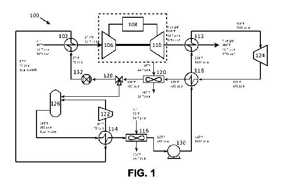
Figure 1 discloses a system 100 in accordance with one embodiment of the
present invention. In system 100, ammonia is utilized to achieve a system that
enables one to address inlet cooling issues in a gas turbine and/or an
internal
combustion engine while also yielding a supercritical ammonia based heat
engine as
a second cycle using the waste heat from the gas turbine and/or internal
combustion
8
CA 02766637 2011-12-22
WO 2010/151560 PCT/US2010/039559
engine to create a combined power cycle. As is illustrated in Figure 1, system
100
includes a heat exchanger 102 that is designed to lower the inlet temperature
of air
supplied to turbine 104. Turbine 104 can be any suitable turbine including,
but not
limited to, a gas turbine. In one embodiment, turbine 104 is composed of
compressor 106, combustor 108 and turbine 110. As should be recognized by
those of skill in the art, the present invention is not limited to just a gas
turbine, or to
a gas turbine having the afore-mentioned configuration. Rather, the present
invention is to be broadly construed and is applicable to a wide range of air-
breathing
engines, or other industrial processes such as gas or air compression, where
the
temperature control of inlet air is desired. As used herein, any compressor
utilized in
conjunction with the embodiments of the present invention can be independently
selected from a mechanical compressor or a fluid compressor (e.g., an
ejector).
Regarding heat exchanger 102, any suitable heat exchanger can be used
including, but not limited to, one or more heat exchangers that each contain
therein
one or more cores where each core utilizes microchannel technology.
As used herein, "microchannel technology" includes, but is not limited to,
heat
exchangers that contain one or more microchannels, mesochannels, and/or
minichannels. As used herein the terms "microchannels," "mesochannels," and/or
"minichannels" are utilized interchangeably. Additionally, the microchannels,
mesochannels, and/or minichannels of the present invention are not limited to
any
one particular size, width and/or length. Any suitable size, width or length
can be
utilized depending upon a variety of factors. Furthermore, any orientation of
the
microchannels, mesochannels, and/or minichannels can be utilized in
conjunction
with the various embodiments of the present invention.
In another embodiment, a heat exchanger in accordance with the present
invention can be formed with one or more cores having one or more printed
circuit
heat exchange (PCHE) panels. Such panels are known in the art, and are
described
in United States Patent Nos. 6,921,518; 7,022,294; and 7,033,553, all of which
are
incorporated herein by reference, in their entireties, for their teachings
related to
printed circuit heat exchange (PCHE) panels. Other suitable heat exchangers
for
use as a regenerator in the system of Figure 1 are disclosed in United States
Published Patent Application No. 2006/0254759, the disclosure of which is
incorporated herein in its entirety.
9
CA 02766637 2011-12-22
WO 2010/151560 PCT/US2010/039559
In still another embodiment, any type of heat exchanger known to those of
skill in the art can be utilized herein so long as such heat exchanger has the
capacity
to manage and/or meet the thermal requirements of the system in which it is
incorporated. In still yet another embodiment, the present invention is not
only
concerned with providing a system that enables one to address various thermal
management issues in advanced gas turbine engines but also to a system that is
designed to address power management issues.
Regarding turbine 104, flue gases therefrom are supplied by any suitable
conveyance means to another heat exchanger 112. Regarding heat exchanger 112,
this heat exchanger can be selected from heat exchangers similar to those
discussed above with regard to heat exchanger 102. Additionally, as is
illustrated in
Figure 1, inlet air is cooled by heat exchanger 102 and supplied to turbine
104 via
any suitable conveyance means. In turn, the sub-components of turbine 104 are
also suitably connected as is known to those of skill in the art. Regarding
suitable
conveyance means, such means include, but are not limited to, conduits, pipes,
ducts, flues, etc. that are designed to withstand the various environmental
conditions
experienced in the turbine applications disclosed herein. Such design criteria
are not
discussed herein for the sake of brevity as they are well known to those of
skill in the
art.
As can be seen in the embodiment of Figure 1, system 100 utilizes a suitable
working fluid in combination with various heat exchangers and suitable
conveyance
means to pull "heat" from inlet air that enters heat exchanger 102 thereby
yielding
cooled inlet air to turbine 104. Regarding system 100 of Figure 1, the working
fluid
can be any suitable working fluid including, but not limited to, ammonia,
carbon
dioxide (be it supercritical or otherwise), nitrogen, inert working fluids, or
any suitable
combination of two or more thereof. In one instance, the system of Figure 1
utilizes
an ammonia working fluid. As will be appreciated upon reading and
understanding
Figure 1, the working fluid of the present invention is not always in a liquid
state.
Rather, as would be apparent to those of skill in the art, the working fluid
of the
present invention undergoes various phase changes in order to accomplish the
stated goals of system 100.
CA 02766637 2011-12-22
WO 2010/151560 PCT/US2010/039559
As can be seen in Figure 1, system 100 contains various additional heat
exchangers (e.g., heat exchangers 114, 116, 118 and 120), at least one
additional
compressor (e.g., 122), at least one additional expander (e.g., 124), a
suitable
number of valves (e.g., 128), a static mixer (e.g., 126), at least one pump
(e.g., 130)
and at least one expansion valve (e.g., 132). As would be appreciated by those
of
skill in the art, the process parameters detailed in Figure 1 are exemplary in
nature
and in no way are meant to limit the scope of the present invention. Rather,
the
present invention is broadly applicable to a wide range of situations where it
is
desired to "pull" heat from one point, or area, of a system and "move" it to
another
point, or area.
In another embodiment, static mixer 126 can be modified as follows. The
mixer 126 could be designed to have low temperature liquid coming in the top,
high
temperature vapor coming in from suitable point in the middle with any
additional
cooling needed for condensing being added. This condensing could be integrated
with heat exchangers 114 and 116. All condensed liquid will be pulled off the
bottom.
Regarding the additional components in the two bottom loops of system 100,
the various additional heat exchangers can be selected from the heat
exchangers
discussed above. The at least one additional compressor (e.g., 122), the at
least
one additional expander (e.g., 124), the valves (e.g., 126 and 128), the at
least one
pump (e.g., 130) and the at least one expansion valve (e.g., 132) can be
selected
from a wide range of known components of these types that are available on the
market, or can be purpose-designed for the disclosed system. Again, the
additional
components of the bottom loops of Figure 1 are connected via suitable
conveyance
means selected from those discussed above. The type of components selected in
this case will depend on the exact design specifications of the system to be
created.
One such arrangement for all of the above identified components of system
100 is illustrated in Figure 1. In Figure 1, system 100 is utilized to reduce
the
temperature of inlet air from an ambient of, for example, 86 F to 59 F. This
is
accomplished by utilizing heat exchanger 102 and a working fluid that is
supplied to
heat exchanger 102. The reduced temperature air is then supplied as inlet air
to
turbine 104 which is designed to burn fuel (e.g., natural gas, coal or oil)
and supply
exhaust gas and waste heat to heat exchanger 112.
11
CA 02766637 2011-12-22
WO 2010/151560 PCT/US2010/039559
In another embodiment, various components of system 100 can be eliminated
to yield a simplified system depending upon the goal to be accomplished.
Alternatively, various components of system 100 can be replaced by control
valves
and an ejector. Figure 3 is an illustration of a system 300 showing the
ejector 334 in
place of compressor 122 from Figure 1. The driving fluid for the ejector can
be
derived from prior to heat exchanger 318, prior to heat exchanger 312 or prior
to
expander 324. A control valve will be added to the system at the optimal point
for
removing fluid to act as the driving fluid for the ejector.
In another embodiment, components can be added to system 100 in order to
separate and collect any hydrogen or nitrogen gas created during thermal
cycling of
the ammonia working fluid within the heat engine. Figure 4 is an illustration
of a
system 400 which uses the same heat engine and inlet cooling as Figure 1.
However, system 400 includes a Haber process reactor to regenerate ammonia.
Figure 4 shows the addition of flash tank 434 which separates gaseous nitrogen
and
hydrogen still present after ammonia condensing step in heat exchanger 420.
Gaseous nitrogen and hydrogen are separated in flash tank 434 and supplied to
compressor 436 where they are compressed to reaction pressure. Compressed
nitrogen and hydrogen are delivered to a catalytic reactor 438 with the
product being
gaseous ammonia and excess nitrogen and hydrogen being recycled to the front
end
of the reactor. Heat will need to be delivered to catalytic reactor 438, this
could
come from an external source or from internal waste heat. This ammonia is
expanded through expansion valve 440 to the low side operating pressure of the
heat engine. The expanded fluid is combined with compressed gas valve 442. All
other components within Figure 4 are consistent with Figure 1. In still
another
embodiment, system 400 can be designed to utilize a CO2 Brayton or Rankine top
cycle to handle the direct exchange from a gas turbine exhaust (Figure 5).
Figure 2 is an illustration of a system 200 in accordance with another
embodiment of the present invention where exit gases of turbine 204 are cooled
using a working fluid based system in accordance with the present invention.
In one
embodiment, the working fluid is carbon dioxide. However, this embodiment is
not
limited thereto. Rather, any suitable working fluid, or combination of working
fluids,
can be utilized in connection with this embodiment. Turbine 204 of system 200
is
composed of compressor 206, combustor 208 and turbine 210. Turbine 204
12
CA 02766637 2011-12-22
WO 2010/151560 PCT/US2010/039559
supplies flue gases to heat exchanger 212 which are then cooled and supplied
for
further cooling to heat exchanger 250. Heat exchangers 212 and 250 are
connected
to a double loop system that utilizes a working fluid selected from those
discussed
above to pull heat from the flue gases generated by turbine 204. As used
herein,
"turbine" is intended to mean a gas turbine, a gas turbine engine, an internal
combustion engine, or any other item of industrial process equipment that
produces
exhaust and takes in air.
As shown in Figure 2, system 200 includes at least one additional heat
exchanger (e.g., 256 and 258), at least one additional compressor (e.g., 252),
at
least one additional expander (e.g., 254), various valves (e.g., 260 and 262),
and at
least one pump (e.g., 260). Again, the additional components of the bottom
loops of
Figure 2 are connected via suitable conveyance means selected from those
discussed above. The type of components selected in this case will depend on
the
exact design specifications of the system to be created.
As would be appreciated by those of skill in the art, the process parameters
detailed in Figure 2 are exemplary in nature and in no way are meant to limit
the
scope of the present invention. Rather, the present invention is broadly
applicable to
a wide range of situations where it is desired to "pull" heat from one point,
or area, of
a system and "move" it to another point, or area.
Figure 5 is an illustration of yet another embodiment of the present invention
where the present invention contains at least two distinct loops and each loop
utilizes
its own working fluid. In one instance, each loop can use the same or
different
working fluids. Suitable working fluids are chosen from those noted above. In
another embodiment, different working fluids are utilized in each loop. In one
instance, one loop utilizes C02 as a working fluid and the other utilizes
ammonia
(NH3). As can be seen in Figure 5 inlet air for a gas turbine is cooled using
a dual
cycle system where one cycle utilizes carbon dioxide as a working fluid and
the other
cycle utilizes ammonia as a working fluid. In this embodiment, the two cycles
are
interconnected via one heat exchanger.
The system 500 of Figure 5 comprises a heat exchanger 502 that is
positioned at the inlet end of a gas turbine 504, wherein heat exchanger 502
is of a
type or design as discussed above and is able to utilize a working fluid to
condition
the temperature of an inlet gas (e.g., air) prior to entry of the inlet gas
into gas
13
CA 02766637 2011-12-22
WO 2010/151560 PCT/US2010/039559
turbine 504. Gas turbine 504 supplies waste heat to a waste heat exchanger 506
which is of a type or design as discussed above. Waste heat exchanger 506 is
operatively coupled to a turbine 508 and a pump 510. As can be seen from
Figure 5,
pump 510 is also operatively coupled to a condenser 512. Turbine 508,
condenser
512 and a second turbine 514 are all operatively coupled to a heat exchanger
516 as
is illustrated in Figure 5. Turbine 514 is operatively coupled to a second
condenser
518. Condenser 518 is, as is illustrated in Figure 5, also operatively coupled
to a
compressor, or pump, 520, a expansion valve 522 and a second pump 524, as is
illustrated in Figure 5. Compressor, or pump, 520 and expansion valve 522 are
also
both operatively coupled to heat exchanger 502 in the manner illustrated in
Figure 5.
Finally, in the embodiment of Figure 5, second pump 524 is operatively coupled
to
heat exchanger 516 in a manner illustrated in Figure 5.
Regarding Figures 1 through 5, these Figures illustrate embodiments of the
present invention that are designed to achieve the simultaneous air, or gas,
inlet
cooling in combination with the utilization of waste heat from any industrial,
or
combustion, process. Given this, Figures 1 through 5 are illustrative of only
exemplary embodiments of the present invention and thus, modifications of
these
embodiments are within the scope of the present invention and would be
apparent to
one of skill in the art.
Industrial, or combustion, processes that benefit from the systems of the
present invention include any industrial, or combustion, processes where such
a
process becomes more efficient when a gas (e.g., air) is conditioned in such a
manner as to increase its density and/or reduce its temperature. In one
embodiment, such processes include, but are not limited to, those processes
carried
out by gas turbines, internal combustion engines, air compressors, gas
compressors,
or any combination thereof. In one embodiment, the present invention is
advantageous in that it permits the temperature conditioning of an inlet gas
in order
to permit an increase in the operating efficiency of a device that is subject
to
performance degradation when the inlet temperature of the intake gas
increases.
In still another embodiment, the present invention comprises a combination of
a sub-system designed to achieve the temperature conditioning of a gas (e.g.,
an
inlet gas or inlet air for an industrial process) with a sub-system designed
to utilize
waste heat to power the sub-system designed to achieve the temperature
14
CA 02766637 2011-12-22
WO 2010/151560 PCT/US2010/039559
conditioning as well as, in some embodiments, permit the waste heat sub-system
to
generate additional usable energy or power that can be utilized for any
desired
purpose. Thus, in this embodiment, the waste heat sub-system of the present
invention is sometimes referred to herein as a bottom loop, circuit, or cycle
that
utilizes a working fluid, as defined herein, to achieve the aforementioned
goal(s).
Accordingly, in one instance, the present invention achieves the integration
of a sub-
system designed to achieve the temperature conditioning of a gas (e.g., an
inlet gas
or inlet air for an industrial process) with a sub-system designed to utilize
waste heat
to drive the aforementioned temperature conditioning sub-system as well as to
permit the waste heat sub-system to generate additional usable energy or power
that
can be utilized for any desired purpose. In one instance, this embodiment is
achieved by a bottom loop (as can be seen in the bottom portions of Figures 1
through 5), that utilizes waste heat provided to the bottom loop to drive and
accomplish the aforementioned temperature conditioning as well as operating as
a
heat engine that can generate, or produce, additional power, or energy, that
can be
exported out of the system and used for any desired purpose.
Regarding the temperatures and/or pressures disclosed in any, or all of,
Figures 1 through 5, these temperatures and pressures are exemplary in nature.
As
would be apparent to those of skill in the art, depending upon the device
and/or
conditions to which the present invention is being applied such temperatures
and
pressures may, can or will change. Additionally, in some instances, the
systems of
the present invention will be transcritical or supercritical. As such, as
would be
known to those of skill in the art upon reading and understanding the present
disclosure, some portions of the systems of the present invention will be sub-
critical,
while other portions will be supercritical. In fact, one aspect of the
inventive system
is that the working fluid may be a supercritical fluid, a sub-critical liquid
and/or a sub-
critical vapor in different locations within the inventive system.
Although the invention has been described in detail with particular reference
to certain aspects detailed herein, other aspects can achieve the same
results.
Variations and modifications of the present invention will be obvious to those
skilled
in the art, and the present invention is intended to cover in the appended
claims all
such modifications and equivalents.