Note: Descriptions are shown in the official language in which they were submitted.
CA 02766753 2014-03-07
79225-131
KNEE BOLSTER FOR VEHICLE
BACK GROUND OF THE INVENTION
The present invention relates to a knee bolster for a vehicle.
Field of the Invention
Knee bolsters including a first arm which promotes deformation during the
collision and a second arm connected to the first arm are known. For example,
Japanese
Unexamined Patent Application, First Publication No. 2007-284034 discloses a
knee
bolster in which a first arm and a second arm connect an arm guide mounted on
a steering
member and a plate to which a load from a knee is applied during the
collision. In this
knee bolster, tip ends of the first arm and the second arm are arranged in
parallel along
the direction perpendicular to the load application direction and are
connected to the plate.
That is, the tip ends of the first arm and the second arm are arranged along a
surface of
the plate.
According to this structure, when the knee of the occupant strikes on the
plate,
the load is simultaneously applied to the first arm and the second arm via the
plate.
Description of the Related Art
Meanwhile, the load applied to the knee bolster may become large or small
depending on the usage or non-usage of a seat belt by the occupant, the
velocity of the
vehicle at the time of the collision, and the like. In the related art, the
amount of the
1
CA 02766753 2012-02-07
impact absorption is designed to absorb only a large load. More specifically,
the knee
bolster is made from a member having a relatively high rigidity so as not to
immediately
reach the end of the deformation stroke when high impact force is applied to
the knee
bolster, thereby stably protecting the knee of the occupant.
However, this related art does not expect a case where a relatively small load
is
applied to the knee bolster. Accordingly, when the impact force does not reach
the
force needed to deform the knee bolster, the knee bolster will not be
deformed. As a
result, the load applied to the knee of the occupant will increase.
An object of the present invention is to provide a knee bolster for a vehicle
capable of suitably absorbing impact to the knee of the occupant in accordance
with the
amount of the applied load.
SUMMARY OF THE INVENTION
The present invention employs the following configurations for solving the
above problem.
(1) A first aspect of the present invention is a knee bolster for a
vehicle, the knee
bolster being adapted to be deformed when a load is applied from a knee of an
occupant
in a load application direction so as to absorb an impact to the knee, the
knee bolster
having, a first bracket which includes: a first support portion which is
supported by a
vehicle body member and extends toward the knee; a first load receiving
portion which
extends from an extended tip end of the first support portion in a direction
which crosses
the load application direction; and a first deformation portion which is
arranged between
the first support portion and the first load receiving portion, and is adapted
to be
2
CA 02766753 2012-02-07
deformed when the load is applied, and a second bracket which includes: a
second
support portion which is supported by the vehicle body member or the first
bracket and
extends along the first support portion; a second load receiving portion which
extends
along the first load receiving portion; and a second deformation portion which
is arranged
between the second support portion and the second load receiving portion, and
is adapted
to be deformed when the load is applied; wherein the second bracket is
arranged such that
the distance between the second load receiving portion and the knee is shorter
than the
distance between the first load receiving portion and the knee, in the load
application
direction.
(2) In the knee bolster for a vehicle according to (1), the first bracket may
include a first
tip end portion at an opposite side of the first deformation portion with
respect to the first
load receiving portion; and the second bracket may include a second tip end
portion at an
opposite side of the second deformation portion with respect to the second
load receiving
portion, and the second tip end portion may be arranged such that a distance
between the
second tip end portion and the knee is shorter than a distance between the
first tip end
portion and the knee, in the load application direction.
(3) In the knee bolster for a vehicle according to (2), the distance
between the second
deformation portion and the second tip end portion may be set longer than a
distance
between the first deformation portion and the first tip end portion.
(4) In the knee bolster for a vehicle according to (1), the second deformation
portion
may be arranged such that a distance between the second deformation portion
and the
knee is shorter than the distance between the first deformation portion and
the knee in the
load application direction.
(5) In the knee bolster for a vehicle according to one of (1) to (4), the
first bracket may
differ from the second bracket in at least one of material, thickness, and
cross sectional
3
CA 02766753 2012-02-07
. .
shape, whereby the first bracket may be formed to have a rigidity or a
strength higher
than that of the second bracket.
(6) In the knee bolster for a vehicle according to one of (1) to
(5), the first support
portion may be formed to have a U-shaped cross section with a bottom wall and
a pair of
side walls; the second support portion may be formed to have a U-shaped cross
section
with a bottom wall and a pair of side walls, the second support portion being
formed
wider than the first support portion; and the first bracket and the second
bracket may be
coupled with each other by coupling the pair of the side walls of the first
support portion
and the pair of the side walls of the second support portion.
Effects of the Invention
According to the structure as described in (1), the second load receiving
portion
of the second bracket is arranged closer to the knee than the first load
receiving portion of
the first bracket in the load application direction from the knee. Therefore,
when the
load applied from the knee is small (for example, in a low impact mode such as
a mode in
which the occupant wears a seat belt or the vehicle velocity is low at the
time of the
collision), the second load receiving portion receives the load whereby the
second bracket
is primarily deformed to absorb the impact. In addition, when the load applied
from the
knee is large (for example, in a high impact mode such as a mode in which the
occupant
does not wear a seat belt or the vehicle velocity is high at the time of the
collision), the
second load receiving portion receives the load whereby the second bracket is
primarily
deformed to absorb the impact, and thereafter, both of the second load
receiving portion
and the first load receiving portion receive the load whereby both of the
second bracket
and the first bracket are deformed to absorb the impact. Therefore, in a case
where the
applied load is small, the impact can be absorbed by the primal deformation of
the second
4
CA 02766753 2012-02-07
bracket, and in a case where the applied load is large, the impact can be
absorbed by the
deformations of the first bracket and the second bracket, before reaching the
end of the
deformation stroke. Accordingly, impact to the knee of the occupant can be
preferably
absorbed in accordance with the amount of the applied load.
According to the structure as described in (2), the second bracket is arranged
such that, not only the second load receiving portion, but also the second tip
end portion
is arranged closer to the knee than the first bracket in the load application
direction from
the knee. Therefore, in a case where the load applied from the knee is small
(that is, in
the low impact mode), only the second bracket can be stably deformed.
According to the structure as described in (3), the distance between the
second
deformation portion and the second tip end portion is set longer than the
distance between
the first deformation portion and the first tip end portion. Therefore, in a
case where a
load applied from the knee is large (that is, in the high impact mode), the
deformed
second bracket can stably contact with the first bracket. Accordingly, the
first bracket
can stably absorb the impact, whereby a large impact can be absorbed before
reaching the
end of the deformation stroke.
According to the structure as described in (4), the second deformation portion
of
the second bracket is arranged closer to the knee than the first deformation
portion of the
first bracket in the load application direction from the knee. Therefore, in a
case where
a load applied from the knee is small (that is, in the low impact mode), only
the second
bracket can be stably deformed.
According to the structure as described in (5), the first bracket is formed to
have
a rigidity or a strength higher than that of the second bracket. Therefore, in
a case
where a load applied from the knee is small (that is, in the low impact mode),
the second
bracket can be stably deformed to absorb the impact, and in a case where a
load applied
5
CA 02766753 2012-02-07
Av..
from the knee is large (that is, in the high impact mode), it is possible to
increase the
impact absorption amount by the first bracket so as to absorb the impact
before reaching
the end of the deformation stroke. In addition, since the first support
portion of the first
bracket has a high rigidity to suppress the deformation of the first support
portion, a
preferable loading characterization can be achieved. Further, the interference
to the
vehicle body provided behind the first support portion can be suppressed so as
to stabilize
the applied load.
According to the structure as described in (6), the first bracket and the
second
bracket are coupled with each other by coupling the pair of the lateral side
walls of the
first support portion and the pair of the lateral side walls of the second
support portion.
Therefore, it is possible to prevent the first support portion and the second
support
portion from being outwardly deformed, whereby the deformation of the first
support
portion and the second support portion can be suppressed. Accordingly, the
first
deformation portion and the second deformation portion can be stably deformed
so as to
achieve the preferable loading characterization of the first bracket and the
second bracket.
Further, it is possible to suppress the interference to the vehicle body
member provided
behind the first support portion and the second support portion so as to
stabilize the
applied load.
BRIEF DESCRIPTION OF THE DRAWINGS
FIG. 1 is a side view of a front area of the vehicle interior including a knee
bolster for a vehicle according to an embodiment of the present invention;
FIG. 2 is a side view of the knee bolster for the vehicle according to the
embodiment of the present invention;
6
CA 02766753 2012-02-07
,..
FIG. 3 is a perspective view of the knee bolster for the vehicle according to
the
embodiment of the present invention;
FIG. 4 is a side view of the knee bolster for the vehicle according to the
embodiment of the present invention, indicating dimensional relationships;
FIG. 5A is a side view of the knee bolster for the vehicle before the
deformation;
FIG. 5B is the side view of the knee bolster for the vehicle at the early
stage of
the deformation:
FIG. 5C is the side view of the knee bolster for the vehicle at the late stage
of the
deformation; and
FIG. 6 is a diagrammatic view indicating a relationship between the applied
load
(vertical axis) and the deformation stroke (horizontal axis) of the knee
bolster for the
vehicle according to the embodiment of the present invention.
DETAILED DESCRIPTION OF THE INVENTION
Hereinafter, a knee bolster 11 for a vehicle according to an embodiment of the
present invention will be explained with reference to the attached drawings.
In the
following explanation, the terms indicating directions such as "up and down",
"right and
left", and "front and rear" mean each direction with respect to the vehicle,
when the knee
bolster 11 is mounted on the vehicle.
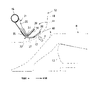
As illustrated in FIG. 1, the knee bolster 11 for the vehicle according to the
present embodiment is arranged in an instrument panel 12 of the vehicle. The
knee
bolster 11 for the vehicle is adapted to be deformed by the load applied from
the knee k
of the occupant H who sits down on a seat 13, so as to protect the occupant H
by
absorbing the impact to the knee k.
7
CA 02766753 2012-02-07
k=
The instrument panel 12 is fixed to a front pillar (not shown) of the vehicle
body
via a steering hanger beam 15 which is provided in the instrument panel 12.
The
steering hanger beam 15 is a vehicle body member used as a part of a frame of
the
vehicle body. The steering hanger beam 15 is a cylindrical steel pipe and
connects the
right and left front pillars along the width direction of the vehicle. Though
it is not
shown in figures, the steering hanger beam 15 supports a steering shaft and
the like.
The instrument panel 12 includes a knee panel 17 which is arranged in front of
the knee k of the occupant H and which extends obliquely upward and rearward,
and a
main panel 18 which substantially vertically extends from the knee panel 17.
When the
occupant H is in a normal sitting posture, the knee k of the occupant H
extends obliquely
downward and frontward. Accordingly, the load application direction F from the
knee k
of the occupant H to the instrument panel 12 at the time of the vehicle front
collision is
the obliquely upward and frontward direction. The knee panel 17 has a surface
shape
which intersects with the load application direction F at a substantially
right angle.
The knee bolster 11 for the vehicle according to this embodiment is supported
by
the steering hanger beam 15 and is arranged between the steering hanger beam
15 and the
knee panel 17. This knee bolster 11 includes a first bracket 21 which is fixed
to the
steering hanger beam 15 and a second bracket 22 which is fixed to the first
bracket 21.
The first bracket 21 is an integrally formed member which is press-formed from
a piece of a steel sheet. The first bracket 21 includes a first support
portion 25, a first
load receiving portion 26, and a first deformation portion 27. The first
support portion
is supported by the steering hanger beam 15 and extends obliquely downward and
rearward to the knee panel 17. The first load receiving portion 26
extends obliquely
upward and rearward from the extended tip end of the first support portion 25
along the
25 knee panel 17. The first deformation portion 27 is provided between the
first support
8
CA 02766753 2012-02-07
44
portion 25 and the first load receiving portion 26 and has a curved shape
which can be
easily deformed.
In this structure, since the knee k of the occupant H is disposed at a
position
apart from the knee panel 17 in the downward and rearward direction, the first
support
portion 25 extends from the steering hanger beam 15 to the knee k. In
addition, since
the knee panel 17 extends along the direction which intersects with the load
application
direction F at a substantially right angle as mentioned above, the first load
receiving
portion 26 also extends along the direction as same as that of the knee panel.
The first support portion 25, the first deformation portion 27, and the first
load
receiving portion 26 are continuously formed, and the first bracket 21 has a
substantially
V shape as a whole when viewed from a side view. In the first bracket 21, the
first load
receiving portion 26 receives the load applied in the load application
direction F from the
knee k at the time of the vehicle front collision, and the first deformation
portion 27,
which primarily receives the load, is plastically deformed so as to absorb the
impact.
As illustrated in FIG. 2 and FIG. 3, the first support portion 25 has a U-
shaped
cross section formed by a bottom wall 25a and a pair of side walls 25b. The
bottom
wall 25a is fixed to the lower portion of the steering hanger beam 15 along
the width
direction of the vehicle by welding or the like, and extends obliquely
downward and
rearward. The pair of the side walls 25b vertically extends from the lateral
ends of the
bottom wall 25a and is fixed to the rear portion of the steering hanger beam
15, by
welding or the like. The pair of the side walls 25b has a shape in which the
height from
the bottom wall 25a gradually decreases as the distance from the steering
hanger beam 15
increases.
The first deformation portion 27 has a bottom wall 27a and a pair of side
walls
27b. The bottom wall 27a is continuously formed with the bottom wall 25a of
the first
9
CA 02766753 2012-02-07
support portion 25 and extends rearward. Further, the bottom wall 27a has an
arc-shape
with a center point at the upper side thereof. The pair of the side walls 27b
is
continuously formed with the pair of the side walls 25b of the first support
portion 25 and
vertically extends from the bottom wall 27a with a substantially constant
height.
The first load receiving portion 26 includes a bottom wall 26a and a pair of
side
walls 26b. The bottom wall 26a is continuously formed with the bottom wall 27a
of the
first deformation portion 27 and extends obliquely upward and rearward. The
pair of
the side walls 26b is continuously formed with the pair of the side walls 27b
of the first
deformation portion 27 and vertically extends from the bottom wall 26a with a
substantially constant height.
In the first bracket 21, as illustrated in FIG. 3, a bead 31 is formed on the
lateral
center portion of the bottom walls 25a, 27a, and 26a, through a middle portion
of the first
support portion 25, the first deformation portion 27, and a first tip end
portion 30 which is
opposed to the first deformation portion 27 with respect to the first load
receiving portion
26. This bead 31 upwardly projects from the bottom walls 25a, 27a, and 26a.
That is,
the respective upper surface of the bottom walls 25a, 27a, and 26a has a
convex shape
and the respective lower surface of the bottom walls 25a, 27a, and 26a has a
concave
shape.
The second bracket 22 is also an integrally formed member which is
press-formed from a piece of a steel sheet. As illustrated in FIG. 2, the
second bracket
22 is arranged at the lower side of the first bracket 21 so as to be supported
by the first
support portion 25. The second bracket 22 includes a second support portion
35, a
second load receiving portion 36, and a second deformation portion 37. The
second
support portion 35 is supported by the first bracket and extends obliquely
downward and
rearward along the first support portion 25 of the first bracket 21. The
second load
CA 02766753 2012-02-07
receiving portion 36 extends obliquely upward and rearward from the extended
tip end of
the second support portion 35, along the first load receiving portion 26 (that
is, along the
knee panel 17) at a position closer to the knee panel 17 than the first load
receiving
portion 26 of the first bracket 21. The second deformation portion 37 is
disposed
between the second support portion 35 and the second load receiving portion
36, and has
a curved surface shape which is easily deformed.
The second support portion 35, the second deformation portion 37, and the
second load receiving portion 36 are continuously formed, and the second
bracket 22 also
has a substantially V shape as a whole when viewed from a side view. In this
second
bracket 22, the second load receiving portion 36 receives the load applied
from the knee k
in the load application direction F when the vehicle front collision occurs,
and the second
deformation portion 37 is plastically deformed primarily by the applied load
so as to
absorb the impact.
The second support portion 35 is formed to have a U-shaped cross section
including a bottom wall 35a and a pair of side walls 35b. The bottom wall 35a
is
arranged along the lower side of the bottom wall 25a of the first support
portion 25. The
pair of the side walls 35b vertically extends from the lateral ends of the
bottom wall 35a,
and is fixed to the pair of the side walls 25b of the first support portion
25.
Since the bottom wall 35a is arranged along the bottom wall 25a, the bottom
wall 35a is arranged along the width direction of the vehicle and extends
obliquely
downward and rearward. The distance between the pair of the side walls 35b of
the
second support portion 35 is wider than the distance between the pair of the
side walls
25b of the first support portion 25. Thus, the second support portion 35 is
wider than
the first support portion 25. The pair of the side walls 35b also has a shape
wherein the
11
CA 02766753 2012-02-07
height from the bottom wall 35a decreases as the distance from the steering
hanger beam
15 increases.
The second bracket 22 is arranged such that the pair of the side walls 35b of
the
second support portion 35 is in contact with the both external lateral sides
of the pair of
the side walls 25b of the first support portion 25 of the first bracket 21.
Then, in this
state, the upper edges of the pair of the side walls 25b of the first support
portion 25 are
welded to the inside surface of the pair of the side walls 35b of the second
support
portion 35, by MIG welding (Metal Insert Gas welding) or the like. As a
result,
between the upper edge of the side wall 25b of the first support portion 25
and the side
wall 35b of the second support portion 35, a welded portion 38 is formed to
join them.
Accordingly, the first bracket 21 and the second bracket 22 are coupled with
each other
by joining the side walls 25b and the side walls 35b at the respective lateral
ends of the
first support portion 25 and the second support portion 35.
The second deformation portion 37 includes, as illustrated in FIG. 3, a bottom
wall 37a and a pair of side walls 37b. The bottom wall 37a is continuously
formed with
the bottom wall 35a of the second support portion 35 and extends obliquely
rearward.
Further, the bottom wall 37a has an arc-shape with a center point at the upper
side thereof
The pair of the side walls 37b is continuously formed with the pair of the
side walls 35b
of the second support portion 35 and vertically extends from the bottom wall
37a with a
substantially constant height.
The second load receiving portion 36 includes a bottom wall 36a and a pair of
side walls 36b. The bottom wall 36a is continuously formed with the bottom
wall 37a
of the second deformation portion 37 and extends obliquely upward and
rearward. The
pair of the side walls 36b is continuously formed with the pair of the side
walls 37b of the
12
CA 02766753 2012-02-07
second deformation portion 37 and vertically extends from the bottom wall 36a
with a
substantially constant height.
The bottom wall 36a has a shape in which the width gradually narrows as the
distance from the second deformation portion 37 increases, and extends to the
rear
direction farther than the pair of the side walls 36b. This extended tip end
is provided
with a second tip end portion 40 which is bent or curved and extends obliquely
upward
from the bottom wall 36a. That is, the second bracket 22 includes the second
tip end
portion 40 at the opposed side of the second deformation portion 37 with
respect to the
second load receiving portion 36.
Meanwhile, as illustrated in FIG. 4, the distance L2 between the second
deformation portion 37 (specifically, the center of the deformed portion) and
the second
tip end portion 40 (specifically, the tip end thereof) of the second bracket
22 is set longer
than the distance Ll between the first deformation portion 27 (specifically,
the center of
the deformed portion) and the first tip end portion 30 (specifically, the tip
end thereof) of
the first bracket 21.
Then, as illustrated in FIG. 2 and FIG. 3, the second bracket 22 is also
formed
with a bead 41 on the lateral center portion of the bottom walls 35a, 37a, and
36a through
the second support portion 35, the second deformation portion 37, and a middle
of the
second tip end portion 40 of the second load receiving portion 36. This bead
41
upwardly projects from the bottom walls 35a, 37a, and 36a. That is, the
respective
upper surface of the bottom walls 35a, 37a, and 36a has a convex shape and the
respective lower surface of the bottom walls 35a, 37a, and 36a has a concave
shape.
The bead 41 of the second bracket 22 has a cross section smaller than that of
the bead
portion 31 of the first bracket 21, and is arranged so as to be covered by the
bead portion
31.
13
CA 02766753 2012-02-07
. .
Meanwhile, in the first bracket 21, the first load receiving portion 26 has a
free
end so as not to continue to a portion other than the first deformation
portion 27.
Further, in the second bracket 22, the second load receiving portion 36 has a
free end so
as not to continue to a portion other than the second deformation portion 37.
Furthermore, the bottom walls 35a, 37a, and 36a of the second bracket 22 are
not in
contact with the bottom walls 25a, 27a, and 26a of the first bracket 21 and
are apart
therefrom.
According to the above structure, the second bracket 22 is arranged such that
the
second load receiving portion 36 is apart from the first load receiving
portion 26 of the
first bracket 21 by the predetermined distance in the load application
direction F, at the
side close to the knee k. That is, the distance between the second load
receiving portion
36 and the knee k is shorter than the distance between the first load
receiving portion 26
and the knee k by the predetermined distance, in the load application
direction F.
Further, the second tip end portion 40 of the second bracket 22 is apart from
the first tip
end portion 30 of the first bracket 21 by the predetermined distance L3 in the
load
application direction F, at the side close to the knee k. That is, the
distance between the
second tip end portion 40 and the knee k is shorter than the distance between
the first tip
end portion 30 and the knee k by the predetermined distance L3 in the load
application
direction F. Furthermore, the second deformation portion 37 (specifically, the
center of
the deformed portion) of the second bracket 22 is arranged apart from the
first
deformation portion 27 (specifically, the center of the deformed portion) of
the first
bracket 21 by the predetermined distance L4 in the load application direction
F, at the
side close to the knee k. That is, the distance between the second deformation
portion
37 and the knee k is shorter than the distance between the first deformation
portion 27
and the knee k by the predetermined distance L4 in the load application
direction F.
14
CA 02766753 2012-02-07
In other words, the second bracket 22 is arranged such that the second load
receiving portion 36 is apart from the first load receiving portion 26 of the
first bracket 21
by a predetermined distance in the perpendicular direction to the direction
along the knee
panel 17, at the side close to the knee panel 17. Further, the second tip end
portion 40 of
the second bracket 22 is arranged apart from the first tip end portion 30 of
the first
bracket 21 by a predetermined distance L3 in the perpendicular direction to
the direction
along the knee panel 17, at the side close to the knee panel 17. Furthermore,
the second
deformation portion 37 of the second bracket 22 is arranged apart from the
first
deformation portion 27 of the first bracket 21 by a predetermined distance L4
in the
perpendicular direction to the direction along the knee panel 17, at the side
close to the
knee panel 17.
The first bracket 21 differs from the second bracket 22 in at least one of
material,
thickness, and cross sectional shape, whereby the first bracket 21 is formed
to have a
rigidity or a strength higher than that of the second bracket 22. More
specifically, the
material of the first bracket 21 may have a rigidity and a strength higher
than that of the
material of the second bracket 22, and the first bracket 21 may have a bead 31
with a
cross section larger than that of the bead 41 of the second bracket 22. In
this case, the
first bracket 21 can be made to have a cross section which can exert high
rigidity and
high strength when compared with the second bracket 22.
According to the above mentioned knee bolster 11 for the vehicle, the second
load receiving portion 36 of the second bracket 22 is arranged closer to the
knee k in the
load application direction F from the knee k when the front collision occurs,
than the first
load receiving portion 26 of the first bracket 21. Accordingly, when the load
applied
from the knee k is small (for example, in a low impact mode such as a mode in
which the
occupant wears a seat belt or the vehicle velocity is low at the time of the
collision), as
CA 02766753 2012-02-07
illustrated in FIG. 5A and FIG. 5B, the load applied to the knee k through the
knee panel
17 is received by the second load receiving portion 36, whereby only the
second bracket
22 is easily deformed primarily at the second deformation portion 37 to absorb
the impact.
That is, as indicated through strokes 0, S1, and S2 in FIG. 6, when the
applied load is
small, the plastic deformation of the second bracket 22 primarily starts at
the stroke Sl,
and receives a low load until reaching the stroke S2 while being plastically
deformed to
absorb the impact.
On the other hand, when the load applied from the knee k is large (for
example,
in a high impact mode such as a mode in which the occupant does not wear a
seat belt or
the vehicle velocity is high at the time of the collision), as illustrated in
FIG. 5A and FIG.
5B, the load applied from the knee k through the knee panel 17 is received by
the second
load receiving portion 36, whereby only the second bracket 22 is deformed
primarily at
the second deformation portion 37. Thereafter, the second load receiving
portion 36 of
the second bracket 22 contacts with the first tip end portion 30 of the first
load receiving
portion 26 of the first bracket 21. As a result, the load is received by both
of the second
load receiving portion 36 and the first load receiving portion 26, whereby the
impact
force can be absorbed by the deformation of the second deformation portion 37
and the
first deformation portion 27. That is, as indicated through strokes S2, S3,
and S4 in FIG.
6, after the second bracket 22 contacts with the first bracket 21 at the
stroke S2, the
plastic deformation of the first bracket 21 starts due to a large load at the
stroke S3, and
then absorbing the impact by the plastic deformations of the second bracket 22
and the
first bracket 21, at the stroke S4.
Accordingly, in a case where the applied load is small, the impact can be
absorbed by the deformation which easily occurs, and in a case where the
applied load is
large, the impact can be also absorbed before reaching the end of the
deformation stroke.
16
CA 02766753 2012-02-07
Therefore, in accordance with the amount of the applied load, impact to the
knee k of the
occupant H can be preferably absorbed.
Further, the second bracket 22 is arranged such that not only the second load
receiving portion 36, but also the second tip end portion 40 is closer to the
knee k in the
load application direction F from the knee k than the first bracket 21.
Accordingly,
when the load applied from the knee k is small (that is, in the low impact
mode), only the
second bracket 22 can be stably deformed.
In addition, the distance between the second deformation portion and the
second
tip end portion is longer than the distance between the first deformation
portion 27 and
the first tip end portion 30. Therefore, in a case where the load applied from
the knee k
is large (that is, in the high impact mode), the deformed second bracket 22
can be made
in contact with the first bracket stably. Thus, since it is possible to stably
absorb the
impact force, a large impact can be absorbed before reaching the end of the
deformation
stroke (that is, a two-stage load can be stably received).
In addition, the second deformation portion 37 of the second bracket 22 is
arranged closer to the knee k in the load application direction F from the
knee k than the
first deformation portion 27 of the first bracket 21. Accordingly, when the
load applied
from the knee k is small (that is, in the low impact mode), only the second
bracket 22 can
be stably deformed. In addition, since only the second tip end portion 40 can
be stably
in contact with the first bracket 21, a two-stage load can be received.
In addition, the first bracket 21 is formed to have a rigidity or a strength
higher
than that of the second bracket 22. Therefore, the impact absorption can be
achieved in
two cases, that is, (1) when the load applied from the knee k is small (that
is, in the low
impact mode), the second bracket 22 can be stably deformed so as to absorb the
impact
force, and (2) when the load applied from the knee k is large (that is, in the
high impact
17
CA 02766753 2012-02-07
mode), the impact absorption amount by the first bracket is increased so as to
absorb the
impact before reaching the end of the deformation stroke. In addition, since
the first
support portion 25 of the first bracket has high rigidity, the deformation of
the first
support portion 25 can be suppressed, whereby the preferable loading
characterization
can be achieved. Further, the interference to the steering hanger beam 15
arranged
behind the first support portion 25 can be suppressed so as to stabilize the
applied load.
In addition, the first bracket 21 and the second bracket 22 are coupled with
each
other by joining the first support portion 25 and the second support portion
35 at the right
and left sides of the pair of the side walls 25b and 35b. Therefore, it is
possible to
suppress the outward deformation of the first support portion 25 and the
second support
portion 35 of the first bracket 21 which form a U-shaped cross section, and
suppress the
deformation of the first support portion 25 and the second support portion 35.
Accordingly, the first deformation portion 27 and the second deformation
portion 37 can
be stably deformed so as to stabilize the applied load.
Note that in the above embodiment, the second bracket 22 is supported by the
first bracket 21. However, the present invention is not limited thereto. For
example,
the second bracket 22 can be supported by the steering hanger beam 15.
Further, the
second bracket 22 can be supported by both of the first bracket 21 and the
steering hanger
beam 15.
While preferred an embodiment of the invention has been described and
illustrated above, it should be understood that it is an exemplary of the
invention and is
not to be considered as limiting. Additions, omissions, substitutions, and
other
modifications can be made without departing from the scope of the present
invention.
Accordingly, the invention is not to be considered as being limited by the
foregoing
description, and is only limited by the scope of the appended claims.
18