Language selection

Search

Patent 2766860 Summary

Third-party information liability

Some of the information on this Web page has been provided by external sources. The Government of Canada is not responsible for the accuracy, reliability or currency of the information supplied by external sources. Users wishing to rely upon this information should consult directly with the source of the information. Content provided by external sources is not subject to official languages, privacy and accessibility requirements.

Claims and Abstract availability

Any discrepancies in the text and image of the Claims and Abstract are due to differing posting times. Text of the Claims and Abstract are posted:

  • At the time the application is open to public inspection;
  • At the time of issue of the patent (grant).
(12) Patent: (11) CA 2766860
(54) English Title: COLD START VALVE
(54) French Title: ELECTROVANNE DE DEMARRAGE A FROID
Status: Granted and Issued
Bibliographic Data
(51) International Patent Classification (IPC):
  • B60K 25/00 (2006.01)
(72) Inventors :
  • TURNIS, JUSTIN J. (United States of America)
  • MAHRENHOLZ, JOHN R. (United States of America)
(73) Owners :
  • DEERE & COMPANY
(71) Applicants :
  • DEERE & COMPANY (United States of America)
(74) Agent: BORDEN LADNER GERVAIS LLP
(74) Associate agent:
(45) Issued: 2018-06-12
(22) Filed Date: 2012-02-01
(41) Open to Public Inspection: 2012-08-16
Examination requested: 2016-12-30
Availability of licence: N/A
Dedicated to the Public: N/A
(25) Language of filing: English

Patent Cooperation Treaty (PCT): No

(30) Application Priority Data:
Application No. Country/Territory Date
13/028,845 (United States of America) 2011-02-16

Abstracts

English Abstract


Parasitic hydraulic loading on an engine is significantly reduced during cold
starts by using an unloader valve to divert the flow of hydraulic fluid from a
hydraulic pump to a hydraulic actuator, i.e., load source, recirculating the
hydraulic
fluid between the hydraulic pump and the unloader valve.


French Abstract

Une charge hydraulique parasitique dans un moteur est significativement réduite pendant les démarrages à froid en utilisant une vanne de décharge pour dévier le flux du fluide hydraulique de la pompe hydraulique vers un actionneur hydraulique, soit une source de charge, en faisant recirculer le fluide hydraulique entre la pompe hydraulique et la vanne de décharge.

Claims

Note: Claims are shown in the official language in which they were submitted.

CLAIMS:
1. A work vehicle having a cab and ground engaging means, comprising:
an ignition;
an engine;
a hydraulic motor;
an integrated hydraulic pump having a pump portion and a valve portion,
the valve portion having a first position sending pressurized fluid from the
pump to
the hydraulic motor, a second position allowing hydraulic fluid to recirculate
between the pump portion and the valve portion, and an actuator for moving the
valve portion to the second position, the pump portion operably connected to
the
engine;
an engine speed sensor for detecting an engine speed;
a temperature sensor for detecting a temperature of hydraulic fluid; and
a vehicle controller unit in communication with the engine speed sensor,
the temperature sensor and the actuator, the vehicle controller unit
energizing the
actuator and moving the valve portion from the first position to the second
position
when (1) the ignition is on, (2) the engine speed is lower than a first
predetermined engine speed, and (3) the temperature detected for the hydraulic
fluid is below a predetermined temperature value, the vehicle controller unit
ceasing to energize the actuator of the valve portion and allowing the valve
portion
to return to the first position when the engine speed detected is above a
second
predetermined engine speed value higher than the first predetermined engine
speed.
2. The work vehicle of claim 1 wherein, the first position is a closed
position.
3. The work vehicle of claim 1 wherein, the second position is an open
position.
4. The work vehicle of claim 1 wherein, the actuator is a solenoid.

5. The work vehicle of claim 1 further including a spring biasing the valve
portion to the first position.
6. The work vehicle of claim 1 wherein, the first predetermined engine speed
is 300 rpm.
7. The work vehicle of claim 1 wherein, the second predetermined engine
speed is 850 rpm.
8. The work vehicle of claim 1 wherein, the predetermined temperature value
is 0°C.
9. A work machine comprising:
an ignition;
an engine;
a hydraulic motor;
an integrated hydraulic pump having a pump portion and a valve portion,
the valve portion having a first position sending pressurized fluid from the
pump to
the hydraulic motor, a second position allowing hydraulic fluid to recirculate
between the pump portion and the valve portion, and an actuator for moving the
valve portion to the second position, the pump portion operably connected to
the
engine;
an engine speed sensor for detecting an engine speed;
a temperature sensor for detecting a temperature of hydraulic fluid; and
a vehicle controller unit in communication with the engine speed sensor,
the temperature sensor and the actuator, the vehicle controller unit
energizing the
actuator to move the valve portion from the first position to the second
position
when (1) the ignition is on, the engine is off and (2) the temperature
detected is
below a predetermined temperature value, the valve portion returning to the
first
position when the engine speed detected is above a predetermined engine speed
value.
6

10. The work machine of claim 9, wherein the first position is a closed
position.
11. The work machine of claim 9, wherein the second position is an open
position.
12. The work machine of claim 9 wherein, the actuator is a solenoid.
13. The work machine of claim 9 further including a spring biasing the valve
portion to the first position.
14. A method of reducing parasitic loading during a startup of a work vehicle
having an engine, an engine speed sensor, a temperature sensor, a hydraulic
motor, a hydraulic pump, a hydraulic valve in proximity to the hydraulic pump
and
having an open position and a closed position, and a vehicle controller unit,
the
method comprising the following steps:
a. using the engine speed sensor to determine if the engine speed is
below a first predetermined speed value;
b. using the temperature sensor to determine if the temperature of the
hydraulic fluid is below a predetermined temperature value; and
c. using the hydraulic valve to cause hydraulic fluid moved by the
hydraulic pump to be diverted from the hydraulic motor and to
recirculate between the hydraulic pump and the hydraulic valve
when the engine speed is below the predetermined speed value in
step a and the temperature is below the predetermined temperature
value of step b.
15. The method of claim 14, further including using the hydraulic valve to
cease
recirculation of the hydraulic fluid between the hydraulic pump and the
hydraulic
valve and cause the hydraulic fluid pressurized by the hydraulic pump to be
delivered to the hydraulic motor when the engine speed is above a second
predetermined speed greater than the first predetermined speed.
7

16. The method of claim 14 wherein the first predetermined engine speed is
300 rpm.
17. The method of claim 15 wherein the second predetermined engine speed is
850 rpm.
8

Description

Note: Descriptions are shown in the official language in which they were submitted.


CA 02766860 2012-02-01
COLD START VALVE
Field of the Invention
This disclosure relates to hydraulic unloading valves and, more particularly,
to hydraulic unloading valves suitable for relieving the load form a hydraulic
pump,
and, thereby, an engine under certain conditions such as, for example, cold
starts.
Background of the Invention
Off road equipment such as diesel powered work vehicles can from time to
time experience difficulties making cold starts at cold temperatures such as,
for
example, temperatures less than 0 C. This can, inter alia, result from a
combination of: (1) greater difficulties starting an unloaded engine at cold
temperatures; and (2) the contiguous application of parasitic loading (e.g.,
hydraulic loading) on the engine at startup. As engines become more and more
fine tuned to the work requirements of the vehicle, i.e., built and tuned to
maximize work efficiency as well as energy efficiency, demanding starting
conditions may become a more critical challenge for all.
Summary of the Invention
Described herein is an invention that improves the conditions under which
cold starts are made by significantly lowering the parasitic loading on the
engine.
The parasitic loading is lowered by reducing hydraulic loads on the engine via
unloading valves.
Brief Description of the Drawings
Figure 1 is an illustrative example of a work vehicle on which the invention
may be used for cold starts;
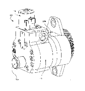
Figure 2 is a perspective view of an exemplary hydraulic pump and
integrated unloader valve;
Figure 3 is an exemplary view of a hydraulic circuit utilizing the invention;
and
Figure 4 illustrates an exemplary flow chart for the invention.
1

CA 02766860 2012-02-01
Description of the Preferred Embodiment
Figure 1 illustrates a work vehicle 10, having a cab 18 and ground
engaging means 20, that may incorporate the invention for the purpose of
improving cold starts. In such vehicles there may be many parasitic hydraulic
loads, e.g., pumps for hydraulic fans, hydrostatic charge pumps, etc..
Parasitic
hydraulic loads may be significantly reduced via the use of unloader valves to
relieve hydraulic loads in areas where functionality requiring such hydraulic
loads
may be, at the time, non-essential. Figure 2 illustrates an exemplary
integrated
hydraulic fan pump 100 having a pump portion 110 and an unloader valve portion
120. While unloading may be accomplished in a non-integrated fashion, such
integration may save valuable space via its compactness, increase reliability
via
reducing the number of exposed and connected parts, and increase efficiency
via
a reduction in the travel distance of hydraulic oil.
Figure 3, is an illustration of a system showing an exemplary embodiment
of the integrated hydraulic pump 100 operably connected to an engine 160,
which
may be, in this embodiment, via a conventional mechanical connection to a
transmission 125; and a vehicle controller unit (VCU) 140 which may be in
electrical communication with a temperature sensor 140a located in hydraulic
fluid
reservoir 150 for detecting the temperature of hydraulic fluid 151 and an
engine
speed sensor 140b which, in this embodiment, may be located within the engine
160. As illustrated, the integrated hydraulic fan pump 100 may include a pump
portion 110 having an inlet 11 Oa and an outlet 110b and an unloader valve
portion
120. The unloader valve portion 120 may have a closed position 120a, an open
position 120b, an actuator which is, in this case, a solenoid 120c, and a
biasing
device which is, in this embodiment, a spring 120d. As illustrated, the
unloader
valve portion 120 may be biased to the closed position 120a via the spring
120d
or other device; it may move to the open position 120b upon being energized by
an electrical signal from the VCU 140 to its solenoid 120c or via some other
method. As illustrated, a hydraulic fan 130 having a hydraulic fan motor 131
and
fan blades 132 may be powered by pressurized hydraulic fluid 151 from the
outlet
110b. The VCU 140 may continually monitor input from the temperature sensor
140a and the engine speed sensor 140b. Also included in this embodiment is a
2

CA 02766860 2012-02-01
conventional ignition (not shown) having on and off positions and a
conventional
starter for the engine. In this embodiment, the engine 160 is started when via
conventional means.
As illustrated, when the unloader valve portion 120 is, by default, in the
closed position 120a, the hydraulic fluid 151 pressurized by the pump portion
110
may flow directly to the hydraulic fan motor 131, thereby biasing the system,
i.e.,
the integrated hydraulic pump 100 toward conventional vehicle operating
conditions, i.e., greater hydraulic loads when the unloader valve portion 120
is not
energized.
When the ignition is on, the engine 160 is off, i.e., when the engine speed
detected by the speed sensor 140b is less than a predetermined speed value
(300
rpm in this embodiment), and the temperature of the hydraulic fluid, as
detected
by the temperature sensor 140a, is less than a predetermined temperature value
of, for example, 0 C as in this embodiment, the VCU 140 signals the unloader
valve portion 120 to move to the open position 120b, thereby allowing
hydraulic
fluid 151 to flow through the unloader valve portion 120. This arrangement may
keep the inlet 110a and outlet 110b to the pump portion open but allow a
significant amount of hydraulic oil moved by the pump portion 110 to
recirculate
between the pump portion 110 and the unloader valve portion 120 and, thereby,
significantly reduce hydraulic loading from the fan motor 131 as fluids tend
to take
the path of least resistance which may be, in this case, the path between the
pump portion 110 and the unloader valve portion 120.
When the engine 160 has achieved a speed greater than 850 rpm as
detected by the engine speed sensor 140b, or the hydraulic fluid 151 has a
temperature greater than or equal to 0 C as detected by the temperature sensor
140a, the VCU 140 stops the energizing signal to the unloader valve portion
120
allowing the unloader valve portion 120 to move to the closed position 120.
Once
the unloader valve portion 120 is in the closed position 120b, the hydraulic
fluid
may cease to recirculate between the pump portion 110 and the unloader valve
portion 120 and follow the new path of least resistance, i.e., moving from the
pump portion 110 to the hydraulic fan motor 131. The unloader valve portion
120
may remain in the closed position until the following three conditions are
met: (1)
3

CA 02766860 2012-02-01
the ignition is on; (2) the engine speed is less than 300 rpm; and (3) the
detected
temperature of the hydraulic fluid 151 is less than 0 C.
The actions above are captured in the logic of the program/routine 200
followed by the VCU 140 as illustrated in the flow chart of Figure 4. As
illustrated
in Figure 4, if the ignition is on at 210 and the engine is off, i.e., the
engine speed
is less than 300 rpm, at 220, and the temperature of the hydraulic fluid 151
is less
than 0 C at 230, unloader valve portion 120 is energized to open at 240. As
illustrated, the unloader valve 120 is energized to remain open until the
engine
160 achieves an engine speed greater than the predetermined speed of 850 rpm.
Once the engine speed is greater than 850 rpm, the unloader valve portion 120
is
de-energized and allowed to close at 260, i.e., the VCU 140 ceases to energize
the unloader valve portion 120. If, at 220, the engine speed is greater than
or
equal to 300 rpm, or at 230, the temperature of the hydraulic fluid 151 is
greater
than or equal to 0 C, the unloader valve 120 is set to close.
Having described the preferred embodiment, it will become apparent that
various modifications can be made without departing from the scope of the
invention as defined in the accompanying claims. The invention has been
described as an integral hydraulic pump and valve arrangement but would work
if
the pump portion 110 and the unloader valve portion 120 were, not integrated,
i.e.,
physically separated, yet in fluid communication with each other.
4

Representative Drawing
A single figure which represents the drawing illustrating the invention.
Administrative Status

2024-08-01:As part of the Next Generation Patents (NGP) transition, the Canadian Patents Database (CPD) now contains a more detailed Event History, which replicates the Event Log of our new back-office solution.

Please note that "Inactive:" events refers to events no longer in use in our new back-office solution.

For a clearer understanding of the status of the application/patent presented on this page, the site Disclaimer , as well as the definitions for Patent , Event History , Maintenance Fee  and Payment History  should be consulted.

Event History

Description Date
Common Representative Appointed 2019-10-30
Grant by Issuance 2018-06-12
Inactive: Cover page published 2018-06-11
Change of Address or Method of Correspondence Request Received 2018-05-25
Inactive: Final fee received 2018-04-23
Pre-grant 2018-04-23
Notice of Allowance is Issued 2017-10-31
Letter Sent 2017-10-31
Notice of Allowance is Issued 2017-10-31
Inactive: Q2 passed 2017-10-27
Inactive: Approved for allowance (AFA) 2017-10-27
Letter Sent 2017-01-11
Request for Examination Requirements Determined Compliant 2016-12-30
All Requirements for Examination Determined Compliant 2016-12-30
Request for Examination Received 2016-12-30
Inactive: Cover page published 2012-08-21
Application Published (Open to Public Inspection) 2012-08-16
Inactive: First IPC assigned 2012-07-31
Inactive: IPC assigned 2012-07-31
Application Received - Regular National 2012-02-16
Letter Sent 2012-02-16
Inactive: Filing certificate - No RFE (English) 2012-02-16

Abandonment History

There is no abandonment history.

Maintenance Fee

The last payment was received on 2018-01-17

Note : If the full payment has not been received on or before the date indicated, a further fee may be required which may be one of the following

  • the reinstatement fee;
  • the late payment fee; or
  • additional fee to reverse deemed expiry.

Patent fees are adjusted on the 1st of January every year. The amounts above are the current amounts if received by December 31 of the current year.
Please refer to the CIPO Patent Fees web page to see all current fee amounts.

Owners on Record

Note: Records showing the ownership history in alphabetical order.

Current Owners on Record
DEERE & COMPANY
Past Owners on Record
JOHN R. MAHRENHOLZ
JUSTIN J. TURNIS
Past Owners that do not appear in the "Owners on Record" listing will appear in other documentation within the application.
Documents

To view selected files, please enter reCAPTCHA code :


To view images, click a link in the Document Description column (Temporarily unavailable). To download the documents, select one or more checkboxes in the first column and then click the "Download Selected in PDF format (Zip Archive)" or the "Download Selected as Single PDF" button.

List of published and non-published patent-specific documents on the CPD .

If you have any difficulty accessing content, you can call the Client Service Centre at 1-866-997-1936 or send them an e-mail at CIPO Client Service Centre.

({010=All Documents, 020=As Filed, 030=As Open to Public Inspection, 040=At Issuance, 050=Examination, 060=Incoming Correspondence, 070=Miscellaneous, 080=Outgoing Correspondence, 090=Payment})


Document
Description 
Date
(yyyy-mm-dd) 
Number of pages   Size of Image (KB) 
Description 2012-01-31 4 187
Abstract 2012-01-31 1 8
Claims 2012-01-31 4 116
Drawings 2012-01-31 3 69
Representative drawing 2012-08-20 1 14
Abstract 2017-10-30 1 8
Representative drawing 2018-05-10 1 10
Maintenance fee payment 2024-01-25 46 1,904
Courtesy - Certificate of registration (related document(s)) 2012-02-15 1 127
Filing Certificate (English) 2012-02-15 1 167
Reminder of maintenance fee due 2013-10-01 1 112
Reminder - Request for Examination 2016-10-03 1 123
Acknowledgement of Request for Examination 2017-01-10 1 176
Commissioner's Notice - Application Found Allowable 2017-10-30 1 162
Request for examination 2016-12-29 1 34
Final fee 2018-04-22 1 31