Note: Descriptions are shown in the official language in which they were submitted.
TITLE WHEELPARROW WAGON CONVERSION
FIELD OF THE INVENTION
The present application relates to a multi-
function wheelbarrow and in particular to a number of
cooperating components that extend the functionality of
the wheelbarrow.
BACKGROUND OF THE INVENTION
A multi-function hand truck is disclosed in my
earlier United States Patents No. 6,945,545 and
7,168,712. The wheelbarrow structure includes moveable
.
front wheels that allow the wheelbarrow to function in
different manners including a vertical storage
capability.
My multi-function wheelbarrow can also function as
a hand truck and includes a pivoting arm structure for
lifting of large loads or containers.
I have found that my convertible wheeled device has
many applications around the home, but has proven
particularly popular as a small wheeLbarrow for gardening
applications. To further extend the functionality of my
wheelbarrow, I have invented a number of cooperating
components that allow my multi-function wheelbarrow to
convert to a wagon structure that preferably includes a
support seat for the user. A number of further
cooperating components are shown including a top support
arrangement for the wheelbarrow when in a wagon
configuration allowing material to be stored on the top
thereof and also a vertically extending rail-type
attachment for securement to a top surface of the wagon
=
CA 2767618 2017-07-25
CA 02767618 2012-02-13
WH 138 -46Cz
configuration. In a further embodiment, additional
carrying capacity in a wheelbarrow application is
achieved by extending the capacity of the wheelbarrow
bucket.
SUMMARY OF THE INVENTION
A garden wagon according to the present invention
comprises an elongate frame with a pair of non steerable
wheels at one end thereof, a pair of side members
extending from the one end towards a second end with the
side members cooperating with the one end to support a
load carrying container generally between and below the
side members. The second end comprises a removable frame
supported by the side frames and mechanically secured
thereto. The removable frame includes a pair of
steerable wheels supported below the removable frame and
a pivoting steering handle coupled to the steerable
wheels and allowing steering of the wagon when pulled by
the handle.
In an aspect of the invention, the removable frame
includes a U-shaped member with two connecting arms
joined at one end of the arms by an intermediate portion.
The connecting arms cooperate with the side members such
that the removable frame closes the second end and forms
an extension of the side frames.
In a further aspect of the invention, the
connecting arms are received in the side frames and form
a rigid extension of the side frames with the steerable
wheel directly below the removable frame and forward of
the load carrying container.
In a different aspect of the invention, a
gardening container as claimed in claim 3 the steerable
- 2 -
wheels include releasable brace members mechanically
connecting a stationary frame supporting the steerable
wheels to the side members.
BRIEF DESCRIPTION OF THE DRAWINGS =
Preferred embodiments of the invention are shown
in the drawings, wherein:
Figure 1 is a perspective view of my convertible
wheelbarrow structure in an operative configuration;
Figure 2 is a perspective view of my wheelbarrow
structure with the wheels moved to a storage position;
Figure 3 is a perspective view of my wheelbarrow
structure in a storage position;
Figure 4 is a perspective view of a wagon wheel
adaptor that can be attached to my wheelbarrow structure;
Figure 5 is a top view illustrating attachment of
my steerable wheel arrangement to one end of the frame of
the multi-function wheelbarrow;
20Figure 6 is a top view similar to Figure 5 showing
=
an alternate adaptive frame for attaching wagon wheels to
one end of my multi-function wheelbarrow;
Figure 7 is a iiew similar to Figure 5
illustrating a single wheel conversion arrangement;
Figure 8 is a perspective view of a seat that can
be applied to opposite sides of the wheelbarrow to
provide a seat for the user; =
Figure 9 is a partial perspective view of a
foldable grid support that can be applied over the top of
the wheelbarrow;
Figure 10 is a perspective view of the support
arrangement of Figure 9 in combination with a rail
arrangement for attachment to the wheelbarrow;
3
CA 2767618 2017-07-25
CA 02767618 2012-02-13
WH 1346C
Figure 11 is a partial perspective view of a
further adaption where the handles of the wheelbarrow can
be secured at one end of the wagon structure;
Figure 12 shows additional details of an adaptive
bracket used in the structure of Figure 11;
Figure 13 is a side view of the multi-function
wheelbarrow converted to a wagon and having upright
supports; and
Figure 14 illustrates a molded wheelbarrow
container of additional capacity that can be attached to
my multi-function wheelbarrow.
DETAILED DESCRIPTION OF THE PREFERRED EMBODIMENTS
My multi-function wheelbarrow is shown in Figures
1, 2 and 3. The wheelbarrow 2 is shown in Figure 1 in
the operational position and the wheels 8 have been moved
and are generally located below the front of the
wheelbarrow container 10. It can be seen that the
wheelbarrow includes two removable handles 6 provided at
the opposite end of the wheelbarrow.
In Figure 2, the wheels have been moved forwardly
and inwardly and are located in front of and generally
within the width of the container 10. This allows the
wheelbarrow structure to in one embodiment function as a
hand truck and additionally to move to the wheels to the
forward position shown in Figure 3. Basically, the
wheelbarrow can store in a vertical orientation supported
by the wheels 8 and a front portion 12 as shown in figure
3.
It has been found that my wheelbarrow structure is
particularly popular for home gardening applications
perhaps due to its multi-function capability, unique
- 4 -
CA 02767618 2012-02-13
WH 13846CA
wheelbarrow configuration and/or the ability to store in
a space efficient manner.
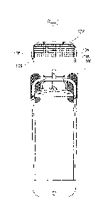
Figure 4 shows my wagon conversion structure that
allows the wheelbarrow to additionally function as a pull
wagon. A wagon adaptor 100 is shown in Figure 4 and
includes a U-shaped frame 102 having two slightly angled
end tubes 104 and 106 that are sized for insertion in the
end rail 20 where the handles 6 are normally secured. In
order to secure the wagon adaptor 100, the handles 6 are
removed and the end tubes 104 and 106 of the U-shaped
bracket 102 are inserted in the upper ports 114 and 116
that normally receive the handles 6. The rails 20 of my
structure slightly diverge from the end 12 towards to the
handles 6 and for this reason the ends 104 and 106 are
slightly tapered to allow the ends 104 and 106 to be
first inserted into the ports 114 and 116 and
subsequently pushed to a secure position.
As shown in Figure 3, the handles 6 are each
secured to the body 25 of the wheelbarrow by bolts 118
and 120 and a handgrip nut shown as 122. To secure my
wagon adaptor 100, the bolts 118 and 120 are removed, the
handles 6 are removed from the wheelbarrow body 25. The
ends 104 and 106 are inserted into the upper ports 114
and 116 that previously received the handles. The bolts
118 and 120 and handgrip nuts 122 are then reinserted and
tightened to secure the ends 104 and 106 to the
wheelbarrow body 25.
The bracket members 130 and 132 are located
beneath the securing portion of the ports 114 and 116 and
are also secured by the bolts 118 and 120. These
basically provide a stabilizer arrangement for the
downwardly extending wheel structure shown as 140. This
downwardly extending wheel structure 140 includes a U-
shaped member 142 secured to member 102 by bolts. Member
- 5 -
CA 02767618 2012-02-13
WH 13846CA
142 is connected by a flat bar member 150 that extends
between the ends of the U-shaped bracket 142. The bar
member 150 supports pivoting bushings 160 of each wheel
between the member 150 and an upper bracket 170.
Basically, the U-shaped member 142 is secured to member
150 by welding (or otherwise securing) the bracket 170 to
the arms of the U-shaped bracket 142. A steering link
180 connects forwardly extending levers 182 and 184 of
each wheel and allow pivoting and steering of the wagon.
A steering handle shown as 190 pivots about 192 and thus,
movement of the handle 190 causes a shifting of the
steering linkage 180.
It can be appreciated that other arrangements for
steering of the wheels 200 and 202 can be provided. The
important aspect is the securement of the wagon adaptor
100 to one end of the frame of my wheelbarrow remote the
original wheelbarrow wheels 8. Preferably, this
securement is achieved using the U-shaped bracket 102
having the end portions 104 and 106 thereof inserted in
the securing ports that normally receive the removable
handles 6. Tightening of the bolts 118 and 120 firmly
secure the U-shaped bracket 102 to the end of the
wheelbarrow remote the original wheels 8 and allow
conversion to a steerable wagon.
With the adaptor 100 secured at the end of my
multi-function wheelbarrow it has now been converted to a
wagon-type structure having a pivoting handle for pulling
and steering of the wagon. The attachment of the wagon
adaptor 100 advantageously uses the existing structure of
the wheelbarrow to allow the wagon adaptor 100 to be a
simple structure that is easily secured.
As previously mentioned, the ends 104 and 106
slightly include a taper for ease of attachment. This
allows the ends 104 and 106 to initially be placed in the
- 6 -
CA 02767618 2012-02-13
WH 13846CA
ports 114 and 116 as there is some play due to the taper.
Once the ends have been inserted, it is then possible to
push the adaptor 100 to a secure position where the bolts
118 and 120 and the handgrip nuts can be reattached. As
can be appreciated, this movement to the securing
position as shown in Figure 5 provides a snug removable
fit of the ends 104 and 106 in the ports 114 and 116.
Furthermore, the wagon adaptor 100 is held in place and
effectively tightened by the bolts 114 and 116.
As shown in the top view of Figure 5, the ends 104
and 106 can also include a tapered insert 105 and 107
that are permanently secured to the ends of the U-shaped
bracket 102. The purpose of the tapered plugs 105 and
107 is to simplify securement while also allowing a snug
fit of the wagon adaptor 100 to the rail members of the
body of the wheelbarrow.
As shown in Figures 4 and 5, the U-shaped bracket
102 preferably includes a cover screen 220. The cover
screen 220 effectively closes the gap between the arms of
the U-shaped bracket and acts as a barrier to the
underlying space used by the steering linkage. This
parallelogram-type steering linkage is a potential safety
hazard and the screen 220 acts as a safety guard against
inadvertent insertion of hands or fingers into this
space.
In the alternate embodiment of Figure 6, the U-
shaped bracket 102 has been broken into a first component
102A and a second component 102B. These components are
secured to each other by a plug portion 103 being
inserted in the end 109 and mechanically fastening the
bolt 111 that passes through the elongate port 113. The
elongate port 113 allows for some play or movement
between the two brackets before the bolt 111 is
tightened. This allows initial insertion of ends 104A
- 7 -
CA 02767618 2012-02-13
WH 13B4 6C
and 106A in the ports 114 and 116. The components 102A
and 102B can then be moved to a secured position where
parts 102A and 102B basically abutt. 102A and 102B are
then fixed by tightened of the bolt 111.
In Figure 7, a different wagon adaptor 100A is
shown that again uses a U-shaped bracket however in this
case, a single wheel is secured beneath the U-shaped
bracket. This structure is somewhat simpler than the
embodiment of Figure 6 or Figure 5 however the single
wheel is not as stable as the dual wheel embodiment. The
double wheel arrangement of Figures 4 and 5 is preferred.
In Figure 7, a seat 150 is shown that is of a size
to straddle the wheelbarrow cavity such that the side
rails of the wheelbarrow pass through the elongate slots
152 and 154. With this arrangement, the seat 150 may be
placed over the wheelbarrow cavity and the top surface of
the seat provides the support for a user. Thus the user
can convert the wheelbarrow structure to the wagon
arrangement and this essentially supports the upper edge
of the wheelbarrow in a horizontal manner. The rails of
the wheelbarrow that are extending from end to end can be
located within the slots 152 and 154. It has been found
that when a person is gardening it may be desirable to
use the seat from time to time. Various arrangements can
be used to secure the seat (including a simple pin
arrangement) if desired.
In Figure 9, a foldable grid support 300 is shown.
This includes a grid portion 302 at one end thereof
having tab-type members 304 and 306. These members can
be fixedly secured to the U-shaped bracket 102 in a
manner as shown in Figure 4. Preferably the grid support
300 includes individual grid sections 302, 310, 312, 314.
316 and 318. These sections are preferably hingedly
connected to one another to allow folding of the support
- 8 -
CA 02767618 2012-02-13
WH 1-i846CA
on the sections to provide a compact storage arrangement.
As can be appreciated, it is desirable that the support
be convertible to a storage arrangement for space
efficiency.
The support 300 is designed to cover the open
cavity of the wheelbarrow and is secured to the
wheelbarrow upper portion in any of a number of different
ways. For example, small tabs may be provided around the
edge of the wheelbarrow cavity to allow securement. An
alternate embodiment is shown in Figure 10 where the
support 300 includes an upper rail portion 380. The
support 300 includes slot areas 385 for receiving the
vertical rail members 382 that are received in ports (not
shown) provided the upper edge of the wheelbarrow. With
this arrangement, the wagon has a rail arrangement
similar to many known child's wagons. The purpose of the
wagon is for gardening-type applications as opposed to a
structure for use by a child. However the rail
arrangement is useful in supporting loads placed on the
support member 300.
Figures 11 and 12 show a further embodiment of the
invention where the bracket member 400 co-operates with
the U-shaped member 102 and provides upwardly extending
securing plugs 402 and 404 for receiving the handles 6.
The handles 6 effectively slide over the plugs 402 and
404 and can be secured thereto by bolts. With this
arrangement, the wagon structure can additionally be
pushed from one end as opposed to being pulled.
In Figure 13, it can be seen that the wagon
structure now has the handles 6 secured in a vertical
manner by the bracket 400 to the U-shaped member 102. In
addition, the lifting arms 75 have been moved to their
normal operating position and form a further upwardly
extending support member. With this structure as shown
- 9 -
CA 02767618 2012-02-13
WH 13846CA
in Figure 13, the wagon includes upwardly extending
members to allow stacking of material on the top support
of the wagon or stacked in the wagon cavity.
In Figure 14, a further embodiment of my invention
is shown wherein a further molded wheelbarrow cavity 500
is shown. This member includes a lower portion 502 that
is shaped for a snug fit within the existing cavity of
the wheelbarrow. Member 500 includes outwardly extending
side members 504 and 506 and outwardly extending end
portions 508 and 510. A series of clips or brackets 512
and 514 can be provided around the perimeter of member
500 for engagement with the upper portion of the
wheelbarrow. In this way, the higher capacity insert 500
can be inserted and held within the wheelbarrow. This
allows the capacity of the wheelbarrow to be extended in
a simply manner and to also allow for other uses that may
require additional capacity. Furthermore, there may be
applications where it is desirable to protect the normal
cavity of the wheelbarrow and this can be done by
inserting the larger cavity member 500.
Member 500 need not include a bottom portion to
provide the additional capacity. In an open structure of
member 500, the bottom portion of the existing
wheelbarrow cavity is used and member 500 merely extends
the sides and end walls.
As shown in the drawings, my convertible
wheelbarrow structure has been further enhanced by the
addition of a wagon adaptor at one end of the wheelbarrow
and a series of additional components that allow the
converted wagon structure and/or wheelbarrow structure to
function in different manners.
Although preferred embodiments of the invention
have been described herein, it would be understood by
- 10 -
CA 02767618 2012-02-13
WH 13B 4 6CA
those skilled in the art that variations may be made
thereto and these variations are intended to be covered
by the appended claims.
- 11 -