Note: Descriptions are shown in the official language in which they were submitted.
CA 02768164 2012-01-13
WO 2011/008832 PCT/US2010/041937
TITLE
PROCESS FOR TREATING AGGLOMERATING OR
BITUMINOUS COAL BY REMOVING VOLATILE COMPONENTS
Inventor: Franklin G. Rinker
STATEMENTS REGARDING FEDERALLY
SPONSORED RESEARCH AND RELATED APPLICATIONS
[0001] The present invention claims the benefit of United States Provisional
Patent
Application No. 61/225,406, filed July 14, 2009, the disclosure of which is
incorporated herein by reference in its entirety. This invention is related to
co-pending
applications entitled "Process For Treating Coal By Removing Volatile
Components,"
and "Process For Treating Bituminous or Agglomerating Coal By Removing
Volatile
Components," filed concurrently herewith. This invention was made with no
Government support and the Government has no rights in this invention.
TECHNICAL FIELD
[0002] The present invention relates to the field of coal processing, and more
specifically to a process for treating agglomerating or various types of
bituminous coal
for the production of coal derived liquids (CDLs) and gaseous fuel, and other
higher
value coal derived products, suitable for use in various industries, including
metallurgical or power production uses.
BACKGROUND OF THE INVENTION
[0003] Coal in its virgin state is sometimes treated to improve its usefulness
and
thermal energy content. The treatment can include drying the coal and
subjecting the
coal to a pyrolysis process to drive off low boiling point organic compounds
and
3o heavier organic compounds. Thermal treatment of coal causes the release of
certain
volatile hydrocarbon compounds having value for further refinement into
transportation liquid fuels and other coal derived chemicals. Subsequently,
the volatile
1
CA 02768164 2012-01-13
WO 2011/008832 PCT/US2010/041937
components can be removed from the sweep gases exiting the pyrolysis process.
Thermal treatment of coal causes it to be transformed into coal char by virtue
of the
evolution of the coal volatiles and products of organic sulfur decomposition,
and the
magnetic susceptibilities of inorganic sulfur in the resultant char are
initiated for
subsequent removal of coal ash, sulfur and mercury from the coal char.
[0004] The effective removal of such volatile components as coal ash,
inorganic
sulfur and organic sulfur, and mercury, from coal char is problematic. It
would be
advantageous if agglomerating or bituminous coal could be treated in such a
manner
that would enable volatile components to be effectively removed from the coal
at more
to desirable concentrations, thereby creating a coal char product having
reduced ash and
sulfur. It would be further advantageous if bituminous coal could be refined
in such a
manner to create a second revenue stream (i.e., condensable coal liquids),
which could
be collected to produce syncrude. A process for treating agglomerating or for
beneficiating bituminous coal, including reducing sulfur and ash, evolving
valuable
coal liquids and fuel gas, increasing calorific value, and improving other
properties of
the resultant coal char product, is desirable.
SUMMARY OF THE INVENTION
[0005] In a broad aspect, there is provided herein a process for treating
agglomerating coal. The process includes providing dried, pulverized,
agglomerating
coal, and treating the coal in a vessel with a gas stream having an oxygen
content
sufficient to form at least some oxides on a surface of the coal particles,
wherein the
oxides are sufficient to convert the coal into substantially non-agglomerating
coal.
The treated coal is transferred into a pyrolyzing chamber and passed into
contact with
an oxygen deficient sweep gas, the sweep gas being at a higher temperature
than the
temperature of the coal so that heat is supplied to the coal. The process
further
includes providing additional heat to coal indirectly by heating the chamber,
wherein
the heating of coal by the sweep gas and by the indirect heating from the
chamber
causes condensable volatile components to be released into the sweep gas. The
sweep
2
CA 02768164 2012-01-13
WO 2011/008832 PCT/US2010/041937
gas is removed from the chamber and treated to remove condensable components
of
coal.
[0006] There is also provided herein a process for treating agglomerating
coal. The
process includes providing dried, pulverized, agglomerating coal, and treating
the coal
in a vessel with a gas stream having an oxygen content sufficient to form at
least some
oxides on a surface of the coal particles, wherein the oxides are sufficient
to convert
the coal into substantially non-agglomerating coal. The treated coal is
transferred into
a pyrolyzing chamber and passed into contact with an oxygen deficient sweep
gas, the
sweep gas being at a higher temperature than the temperature of the coal so
that heat is
1o supplied to the coal. The process further includes providing additional
heat to coal
indirectly by heating the chamber, wherein the heating of coal by the sweep
gas and by
the indirect heating from the chamber causes condensable volatile components
to be
released into the sweep gas. The sweep gas is removed from the chamber and
treated
to remove condensable components of coal. , and wherein some of the oxides are
converted into paramagnetic mineral components. The coal, including the
paramagnetic mineral components, are removed from the pyrolyzing chamber as
coal
char. The paramagnetic mineral components are removed from the coal char,
thereby
creating a coal char having reduced ash and sulfur.
[0007] In certain embodiments, the coal is pulverized to a size within a range
of
from about minus 40 mesh to about minus 200 mesh.
[0008] In certain embodiments, the oxygen content of the gas stream is
sufficient to
cause the coal to gain weight in an amount within a range of from about 0.5%
to about
2.0% of the weight of the coal when the coal is treated for a time of about 30
minutes
at a temperature within a range of from about 400 F to about 600 F.
[0009] In certain embodiments, the treating of the coal with the gas stream
includes
heating the coal to a temperature within a range of from about 400 F to about
650 F in
an oxidizing rotary retort or an oxidizing fluidized bed vessel.
3
CA 02768164 2012-01-13
WO 2011/008832 PCT/US2010/041937
[0010] In certain embodiments, the treated coal is pre-heated to a temperature
within a range of from about 550 F to about 900 F in a pre-heat rotary retort
or a pre-
heat fluidized bed vessel.
[0011] In certain embodiments, the temperature of the pre-heat rotary retort
or pre-
heat fluidized bed vessel is controlled to about 550-900 F so as to remove
about 2% to
about 10% by weight of coal volatile components from the treated coal while
allowing
desirable volatiles to remain with the coal particles.
[0012] In certain embodiments, the pre-heating step removes volatiles from the
treated coal and includes withdrawing off gases from a pre-heat rotary retort
or a pre-
lo heat fluidized bed vessel, and then combusting the volatiles in the off
gases and
transferring thermal energy from the combustion to the pre-heating step.
[0013] In certain embodiments, the pyrolyzing chamber is a rotary retort, and
the
treated coal is heated in the retort to a temperature within a range of from
about 900 F
to about 1200 F so as to produce pulverized coal char, with the sweep gas
removed
from the chamber having a condensable hydrocarbon content of at least about
25%.
[0014] In certain embodiments, the pyrolyzing step creates sulfur in the form
of at
least one of H2S, CS2, and COS, with the H2S, CS2, and COS being removed from
the
chamber with the sweep gas, and further includes removing sulfur from the
sweep gas.
[0015] In certain embodiments, the coal is continuously supplied into one end
of
the chamber and removed from another end of the chamber, the sweep gas is
continuously supplied into one end of the chamber and removed from another end
of
the chamber, and the sweep gas exiting the chamber has a condensable
hydrocarbon
content of at least 25% by weight.
[0016] In certain embodiments, the treated coal entering the chamber includes
pyrite (FeS2) and hematite (Fe203), and wherein the pyrolyzing of the coal in
the
chamber causes the conversion of pyrite to pyrrhotite (Fe758) and the
conversion of
hematite to magnetite (Fe304).
[0017] In certain embodiments, the process further includes the step of
removing
pyrrhotite and magnetite from the coal by magnetic separation.
4
CA 02768164 2012-01-13
WO 2011/008832 PCT/US2010/041937
[0018] In certain embodiments, the coal is cooled to a temperature below 350 F
prior to removing pyrrhotite and magnetite from the coal.
[0019] In certain embodiments, at least 80% of the sweep gas entering the
chamber
is comprised of CO2 and H20-
[0020] In certain embodiments, the sweep gas removed from the chamber includes
at least one of C3H8, CH4, and CO, and further includes at least one of H2S,
CS2, and
COS.
[0021] In certain embodiments, the agglomerating coal has a free-swelling
index
(FSI) of about 4 or more, which is reduced to an FSI of about 1 or less
following
to treatment of the agglomerating coal.
[0022] In another broad aspect, there is provided herein a process for
treating
agglomerating coal. The process includes providing dried, pulverized,
agglomerating
coal, and pre-heating the coal to a temperature within a range of from about
550 F to
about 900 F in a pre-heat rotary retort or a pre-heat fluidized bed vessel.
The coal is
transferred into a pyrolyzing chamber and an oxygen deficient sweep gas is
passed
into contact with the coal, the sweep gas being at a higher temperature than
the
temperature of the coal so that heat is supplied to the coal. The process
further
includes providing additional heat to the coal indirectly by heating the
chamber,
wherein the heating of the coal by the sweep gas and by the indirect heating
from the
chamber causes condensable volatile components to be released into the sweep
gas.
The sweep gas is removed from the chamber and treated to remove condensable
components of the coal.
[0023] In another broad aspect, there is provided herein a process for
treating
agglomerating coal. The process includes providing dried, pulverized,
agglomerating
coal, and pre-heating the coal to a temperature within a range of from about
550 F to
about 900 F in a pre-heat rotary retort or a pre-heat fluidized bed vessel.
The coal is
transferred into a pyrolyzing chamber and an oxygen deficient sweep gas is
passed
into contact with the coal, the sweep gas being at a higher temperature than
the
temperature of the coal so that heat is supplied to the coal. The process
further
5
CA 02768164 2012-01-13
WO 2011/008832 PCT/US2010/041937
includes providing additional heat to the coal indirectly by heating the
chamber,
wherein the heating of the coal by the sweep gas and by the indirect heating
from the
chamber causes condensable volatile components to be released into the sweep
gas.
The sweep gas is removed from the chamber and treated to remove condensable
components of the coal.
[0024] In certain embodiments, the temperature of the pre-heat rotary retort
or pre-
heat fluidized bed vessel is controlled to about 600-900 F so as to remove
about 2% to
about 10% by weight of coal volatile components from the treated coal while
allowing
desirable volatiles to remain with the coal particles.
[0025] In certain embodiments, the pre-heating step removes volatiles from the
treated coal and includes withdrawing off gases from a pre-heat rotary retort
or a pre-
heat fluidized bed vessel, and then combusting the volatiles in the off gases
and
transferring thermal energy from the combustion to the pre-heating step.
[0026] In certain embodiments, the pyrolyzing chamber is a rotary retort, and
the
pre-heated coal is heated in the retort to a temperature within a range of
from about
850 F to about 1200 F so as to produce pulverized coal char, with the sweep
gas
removed from the chamber having a volatile content of at least about 25%.
[0027] In still another broad aspect, there is provided herein a process for
treating
agglomerating coal. The process includes providing dried, pulverized,
agglomerating
coal, and treating the coal in a vessel with a gas stream having an oxygen
content
sufficient to cause the coal to gain weight in an amount within a range of
from about
0.5% to about 2% of the weight of the coal and to form at least some oxides on
a
surface of the coal particles, wherein the oxides are sufficient to convert
the coal into
substantially non-agglomerating coal. The treated coal is pre-heated to a
temperature
within a range of from about 550 F to about 900 F in a rotary retort or a
fluidized bed
vessel. The coal is transferred into a pyrolyzing chamber and an oxygen
deficient
sweep gas is passed into contact with the coal, the sweep gas being at a
higher
temperature than the temperature of the coal so that heat is supplied to the
coal. The
process further includes providing additional heat to the coal indirectly by
heating the
6
CA 02768164 2012-01-13
WO 2011/008832 PCT/US2010/041937
chamber, wherein the heating of the coal by the sweep gas and by the indirect
heating
from the chamber causes condensable volatile components to be released into
the
sweep gas. The sweep gas is removed from the chamber and treated to remove
condensable components of the coal paramagnetic mineral components. The coal,
including the paramagnetic mineral components, are removed from the pyrolyzing
chamber as coal char. The paramagnetic mineral components are removed from the
coal char, thereby creating a coal char having reduced ash and sulfur
[0028] In another broad aspect, there is provided herein a process for
treating
bituminous coal. The process includes providing dried, pulverized coal, and
treating
1o the pulverized coal in a vessel with a gas stream having an oxygen content
sufficient
to cause the coal to gain weight in an amount within a range of from about
0.5% to
about 2.0% of the weight of the coal, and to form oxides on a surface of the
coal
particles. The treated coal is transferred into a pyrolyzing chamber and an
oxygen
deficient sweep gas is passed into contact with the coal, the sweep gas being
at a
higher temperature than the temperature of the coal so that heat is supplied
to the coal.
The process further includes providing additional heat to the coal indirectly
by heating
the chamber, wherein the heating of the coal by the sweep gas and by the
indirect
heating from the chamber causes condensable volatile components to be released
into
the sweep gas, and wherein some of the oxides are converted into paramagnetic
mineral components. The coal, including the paramagnetic mineral components,
are
removed from the pyrolyzing chamber as coal char. The paramagnetic mineral
components are removed from the coal char, thereby creating a coal char having
reduced ash and sulfur.
[0029] Various advantages of this invention will become apparent to those
skilled
in the art from the following detailed description of the preferred
embodiment, when
read in light of the accompanying drawings.
7
CA 02768164 2012-01-13
WO 2011/008832 PCT/US2010/041937
BRIEF DESCRIPTION OF THE DRAWINGS
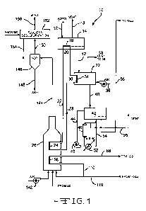
[0030] Figure 1 is a schematic illustration of a process for treating various
types of
bituminous coal.
[0031] Figure 2 is a schematic illustration of a continuation of the process
of Figure
1 for treating agglomerating and various types of bituminous coal.
[0032] Figure 3 is an enlarged, schematic cross-sectional view of a gas-heated
retort used in the process of Figures 1 and 2.
[0033] Figure 4 is an enlarged, schematic side view in cross-section of the
gas-
lo heated retort of Figures 1 and 2.
[0034] Figure 5 is an enlarged, schematic cross-sectional view of an
electrically
heated retort used in the process of Figures 1 and 2.
[0035] Figure 6 is a schematic illustration of a graph showing the thermo-
gravimetric analysis (TGA) of a seam of agglomerating coal having an initial
free-
swelling index (FSI) of 4 subsequently reduced to 1 according to the process
of
Figures 1 and 2.
[0036] Figure 7 is a schematic illustration of a graph showing the thermo-
gravimetric analysis (TGA) of another seam of agglomerating coal having an
initial
free-swelling index (FSI) of 4 subsequently reduced to 1 according to the
process of
Figures 1 and 2.
[0037] Figure 8 is a schematic illustration of a graph showing the thermo-
gravimetric analysis (TGA) of another seam of agglomerating coal having an
initial
free-swelling index (FSI) of 4 subsequently reduced to 1 according to the
process of
Figures 1 and 2.
DETAILED DESCRIPTION OF THE INVENTION
[0038] The process of the present invention pertains to treating agglomerating
coal
and various types of bituminous coal for the production of coal derived
liquids (CDLs)
and other higher value coal derived products, such as a high calorific value,
low
8
CA 02768164 2012-01-13
WO 2011/008832 PCT/US2010/041937
volatile, low ash, low sulfur coal (char), suitable for a variety of uses in
industry,
including metallurgical and power production and the like. Desired amounts of
volatile components are removed from the resultant coal char through the use
of low
temperature carbonization (i.e., less than about 1300 F) so as to refine the
solid
product and to create a second revenue stream, the condensable coal liquids,
which
can be collected to produce syncrude. Further, desirable condensable
hydrocarbon
liquids are removed from the coal at more desirable concentrations than
capable with
conventional coal treating processes. In particular, the process combines the
advantages of pyrolytic heating with an attemperated, high sensible heat
oxygen
to deficient gas stream (sweep gas) coupled with indirect heating by passing a
portion of
the required heat through a rotating metal shell of a rotary pyrolyzer retort
as described
below. Pyrolytic heating is a desirable step in the process as coal feedstock
is
separated into a coal char and a vapor, which when passed through downstream
condensers, such compounds can be separated into coal tar, water, and a fuel
gas.
[0039] The process further combines the advantages of a pretreatment or chemi-
sorption step (apparatus 32) in order to destroy or reduce the caking
properties of the
bituminous coal in refining the coal to a coal char product having reduced ash
and
sulfur. The process is a dual zone pyrolysis process. During the first step,
the
bituminous coal is heated to a certain temperature, and during the second
step, the coal
is heated to a higher temperature than the first step. By using the dual zone
pyrolysis
process, the indirect/direct pyrolytic heating step of the second pyrolysis
step is
optimized. A primary reason for indirect heating is that it maximizes the
vapor
pressure of the condensable hydrocarbon components and minimizes the carryover
or
lofting of fine coal or coal char particles. A further advantage of dual
pyrolysis is to
reduce the thermal requirement for the second pyrolysis step. The operating
temperature in the second pyrolysis step is controlled to maintain a target or
desirable
volatile content in the coal char as some volatile in the coal char is
desirable for both
metallurgical and steam coal char product requirements.
9
CA 02768164 2012-01-13
WO 2011/008832 PCT/US2010/041937
[0040] It is to be understood that the process disclosed herein is suited for
various
types of agglomerating or highly agglomerating bituminous coal, particularly
caking,
coking coal having a free swelling index (FSI) of greater than 1Ø
[0041] In consideration of the figures, it is to be understood that for
purposes of
clarity certain details of construction are not provided in view of such
details being
conventional and well within the skill of the art once the present invention
is disclosed
and described herein.
[0042] Reduction of volatiles, including moisture, involves several thermal
processing steps. Typically, bituminous coals from surface mining operations
are
to washed to remove mineral matter normally associated with these coals.
Washing is
dependent on large density differences between the organic coal substance and
the
mineral matter included therein with the as mined coal. After washing, a
typical
Western Kentucky bituminous coal will have a moisture content of nearly 12% by
weight, even though the equilibrium moisture content is within a range of from
about
7% to about 9%. Therefore, the as-received coal must be dried as the first
step in the
series of thermal steps described below.
[0043] Referring now to Figure 1, a schematic illustration of a process 10 for
treating various types of bituminous coal 12 using indirect gas fired heating
is shown.
A stream of pulverized coal 12 is introduced into a fluidized bed dryer 14
with internal
heating tubes having a heat exchange embedded tubular surface 16. Any suitable
dryer can be used. The coal 12 is pulverized to a size passing 60 mesh prior
to being
introduced into the fluidized bed dryer 14. It should be understood that
further size
reduction of the coal to minus 200 mesh may be required for downstream
separation of
paramagnetic mineral elements. In one embodiment, the coal 12 is pulverized to
a size
within a range of from about minus 40 mesh to about minus 200 mesh. The heat
transfer coils with thermal head (not shown) can range in temperature of from
about
50 F to about 100 F with respect to intended dried coal temperature. The
pulverized
coal 12 can be dried in a fluidized bed dryer at a temperature below 400 F.
The
fluidized bed dryer 14 uses a combination of direct gas/solid heating plus
indirect
CA 02768164 2012-01-13
WO 2011/008832 PCT/US2010/041937
embedded heat transfer coils heating the coal to a temperature within a range
of from
about 300 F to about 425 F. Excess moisture 18 is vented upstream from the
fluidized bed dryer 14.
[0044] A heat exchange manifold 20, which functions as a heat transfer fluid
conduit, is configured within a bottom portion of the fluidized bed dryer 14,
from
which a heat transfer fluid return flows downstream through conduit 22 into a
heat
exchanger 24 for heating the heat transfer fluid. Heat exchanger 24 is
configured
within a waste fuel gas combustor 26 for the combustion of gaseous CH4, CO,
H2S,
and other compounds. A heat transfer fluid conduit 28 exits from the heat
exchanger
l0 24 and flows upstream to a heat exchange manifold 30, which functions as a
heat
transfer fluid conduit, and is configured within a vessel such as a fluidized
bed
chemisorption apparatus 32. While a preferred apparatus 32 for the
chemisorption
process is a fluidized bed heater, an indirectly heated retort (not shown)
having a
retention time of at least 30 minutes can be used in the alternative. The
fluidized bed
chemisorption apparatus 32 includes a heat exchange embedded tubular surface
34
configured therein. An air blower 36 configured outside the fluidized bed
chemisorption apparatus 32 supplies air to the coal 12 during the
chemisorption
treatment process. A vent 38 extends upstream from the fluidized bed
chemisorption
apparatus 32 and directs waste to the waste fuel gas combustor 26 for the
combustion
of gaseous carbon -oxygen compounds, which compounds may be formed during the
chemisorption treatment process.
[0045] Over a temperature range that coincides relatively closely with that of
the
intended active thermal decomposition, bituminous coals pass through a
transient
plastic state in which they soften, swell and finally resolidify into a more
or less
distended cellular cake mass. These coals are referred to as caking coals, as
opposed
to those that do not become plastic on heating, which are referred to as non-
caking
coals. The caking or swelling nature of coals is evaluated using the empirical
free-
swelling test. The free-swelling index (FSI) is commonly used to rank various
coals,
the index having a range of from 1 to 10. Non-caking coals normally exhibit an
FSI of
11
CA 02768164 2012-01-13
WO 2011/008832 PCT/US2010/041937
1 or less. In one embodiment, the coal is substantially non-agglomerating coal
and has
a FSI of 1 or less. Western Kentucky bituminous coals typically have an FSI of
4, or
within a range of from about 1 to about 6. The plastic or coking nature of
these
bituminous coals leads to agglomeration of the coal particles when heated to
the
intended decomposition temperature range of from about 350 F to about 1050 F.
Agglomeration leads to sticking, which phenomenon causes plugging in the
various
heating devices. These caking properties are impediments to the intended
thermal
process and should be destroyed or counteracted, or at least greatly reduced.
[0046] Plastic properties of caking, coking coals when heated are generally
known.
to Coal plastic properties are sensitive to changes in ambient conditions and
are
susceptible to modification. One or more of the ambient conditions described
herein
can be adopted to reduce the plasticity of agglomerating coals. These ambient
conditions include: (1) increasing heating rates will increase the maximum
Gieseler
fluidity, dilatometric dilatation, and extent of free swelling, and
simultaneously raise
the temperatures at which characteristic plasticity parameters begin to
manifest
themselves; (2) prolonged pre-heating of the coal in an inert atmosphere at
temperatures as low as 200 C will progressively diminish fluidity, swelling,
and
related caking indices; (3) increasingly comminuting the coal - even a
strongly caking
coal with FSIs greater than 6-7.7 will yield only a barely coherent coke
button if it is
sufficiently finely pulverized and very slowly heated; (4) reducing the
mineral matter
content will greatly enhance the plastic properties of weakly and moderately
caking
coals with high ash contents, i.e., coals with FSIs between 3 and 5 and ash
contents
greater than 10%; (5) oxidizing (i.e., weathering during prolonged exposure to
air) will
quickly and progressively narrow the plastic range, reduce the maximum
fluidity, and
eventually completely destroy all caking propensity; and (6) suppressing all
manifestations of plasticity by pyrolyzing the coal in vacuo or enhancing by
heating
the coal under elevated pressures. Even mild hydrogenation that seemingly does
not
alter the chemical structure of the coal to any great extent will cause
converse effects,
i.e., broaden the plastic range and increase swelling, fluidity, and the like.
12
CA 02768164 2012-01-13
WO 2011/008832 PCT/US2010/041937
[0047] Pilot plant experiments in accordance with the process disclosed herein
have
shown that pulverized bituminous coal sized to minus 60 mesh can be treated
with
chemisorption of oxygen and slow heating so as to convert the particulate
dried coal to
non-caking coal.
[0048] Exposure of freshly mined coal to air at ambient temperature conditions
for
as little as a few days will cause a marked deterioration of any caking
properties.
While not being bound by any theory, this deterioration of the caking
properties is
believed to be caused by two substantially concurrent processes-(1)
progressive
oxidative destruction of non-aromatic configurations, such as CH3, OCH3, or
(CH2)n,
1o in the coal molecules, and (2) simultaneous chemisorption of oxygen at
aromatic
carbon sites.
[0049] In one embodiment, the coal is treated in a vessel with a gas stream
having
an oxygen content sufficient to form at least some oxides on a surface of the
coal
particles. In yet another embodiment, the oxides are sufficient to convert the
coal into
substantially non-agglomerating coal. In some embodiments, the oxygen content
of
the gas stream is sufficient to cause the coal to gain weight in an amount
within a
range of from about 0.5% to about 2.0% of the weight of the coal 12 when the
coal is
treated for a time of about 30 minutes at a temperature within a range of from
about
400 F to about 650 F. It should be understood that the vessel used for
treatment can
be either an oxidizing fluidized bed vessel 32 or an oxidizing rotary retort
(calciner) of
the type described below.
[0050] Following treatment of the coal by chemisorption, the chemisorbed or
treated coal 40 can be transferred to either a fluidized bed, or, preferably,
a dual zone
pyrolysis, for pre-heating in accordance with the process of the present
disclosure. It
is advantageous to separate the two stages of the dual zone pyrolysis process
for
several reasons, including: (1) to reduce the coal mass flow heating
requirement for
the indirect heating required for the second stage; (2) to reduce the sensible
heat
required for the indirect second stage as coal will enter at about 900 F; (3)
to increase
the partial pressure of the condensables released in the second stage, i.e.,
C5+ and the
13
CA 02768164 2012-01-13
WO 2011/008832 PCT/US2010/041937
like; (4) to bum combustible components released in the first zone in a
slipstream
combustor; and (5) to separately treat effluent for removal of mercury using
activated
carbon.
[0051] In one embodiment, the first zone pre-heats the coal to a temperature
within
a range of from about 550 F to about 900 F in either a pre-heat rotary retort
42 or a
pre-heat fluidized bed vessel (not shown). It is contemplated that the first
zone will
raise the coal temperature to a temperature within a range of from about 550 F
to
about 900 F so as to both pre-heat and produce CO2, CO, and CH4, by partial
pyrolysis. The CO2 is used as a recycle fluidizing gas (i.e., off gas) 44,
partially
to slipstream passing through a combustor 46 and prior to venting so as to
combust any
hydrocarbons or CO that may be involved in the partial pyrolysis process.
Combustion
of any fuel gases other than CO2, including CO, CH4 and the like, will provide
all or a
portion of the thermal energy required for pre-heating and partial pyrolysis
of the coal
in the pyrolyzer 42. It is further contemplated that the temperature in the
first zone is
controlled to about 550-900 F so as to remove about 2% to about 10% by weight
of
coal volatile components from the treated coal 40 while allowing desirable
volatiles to
remain with the coal particles.
[0052] In certain embodiments, the temperature of the first zone is no greater
than
850 F, which is the temperature incipient for release of condensable coal
volatile
vapors.
[0053] In a further embodiment, the pre-heating step removes volatiles from
the
treated coal and includes withdrawing off gases (i.e., C02, CO, CH4 and the
like) 44
from a pre-heat rotary retort 42 or a pre-heat fluidized bed vessel (not
shown), and
then combusting the volatiles in the off gases in combustor 46 and
transferring thermal
energy from the combustion to the pre-heating step 42. The off gases 44 pass
through
a recirculation fan 48 before flowing either through a slipstream combustor
air supply
fan 50 prior to combustion or through a heat exchanger 52 to provide on gas 54
to the
first pyrolysis retort 42. The on gas 54 and first stage coal char 56 from the
pyrolyzer
42 can be vented at 55 as shown in Figure 1.
14
CA 02768164 2012-01-13
WO 2011/008832 PCT/US2010/041937
[0054] Referring to Figures 1 and 2, following pre-heating of the treated coal
40 in
the first zone, the first stage coal char 56 is transferred into a chamber or
pyrolytic
rotary retort 58 for the second pyrolysis step. The chamber can be any vessel
suitable
for heating coal by convection gases as well as heating indirectly by
radiation and
conduction. The dried and pre-heated coal 56 may be pre-sized to a range
between 40
mesh and 200 mesh prior to being charged into the pyrolytic retort 58, but
other sizes
can be used. A rotary valve 60 isolates and controls the flow of the incoming
coal
char 56, which is directed continuously into the rotary retort chamber 58.
[0055] Various reactions in the second pyrolysis step occur at a temperature
within
to a range of from about 900 F to about 1200 F in accordance with the process
of
Figures 1 and 2. These reactions include the release of coal volatiles,
decomposition
of organic sulfur forming H2S, COS, and CS2, conversion of pyrite (FeS2) to
paramagnetic pyrrhotite (Fe7S8), and conversion of other iron oxides to
paramagnetic
oxide forms. The treated coal char 56, which enters the retort 58, includes
pyrite and
hematite (Fe203), and the pyrolyzing of the coal char in the second zone
causes the
conversion of pyrite to pyrrhotite, and the conversion of hematite to
magnetite (Fe304).
[0056] The rotary retort 58 used for the combined direct/indirect pyrolytic
heating
process may be selected from a type of heat transfer device for the indirect
thermal
processing of bulk solid materials commonly referred to as a rotary calciner.
The
rotary calciner consists principally of an alloy rotary shell 62, enclosed in
and
indirectly heated on its exterior in a stationary furnace. The process
material (i.e.,
coal) 56 moves through the interior of the rotary shell 62, where it is heated
through a
combined radiative and convective/conductive mode of heat transfer through the
rotary shell wall 64. Operating temperatures of up to 2200 F can be achieved.
Rotary
calciners can be small pilot-scale units, or full-scale productions units as
large as 10-
12 feet in diameter with a heated length of up to 100 feet. Units can be
heated by a
variety of fuels, such as gas (Figures 3-4), or by electric-resistive heating
elements (see
Figure 5). Waste heat and/or external heat sources can also be accommodated
for
rotary calciners.
CA 02768164 2012-01-13
WO 2011/008832 PCT/US2010/041937
[0057] It is contemplated that the rotary retort 58 is of sufficient length
and
capacity so as to provide pulverized coal particle residence time within a
range of from
about 15 minutes to about 25 minutes, which time is desirable for conversion
of the
non-magnetic pyrite (FeS2) to paramagnetic pyrrhotite (Fe7S8) and for
reduction of the
non-magnetic iron oxides to paramagnetic magnetite. In some embodiments, the
residence time is no greater than 22 minutes, which residence time will not
cause
reduction of the newly formed magnetic iron oxides, forming therefore
undesirable,
non-magnetic wustite (FeO).
[0058] Materials of construction of the rotary shell 62 are selected for high-
lo temperature service, corrosion resistance, and compatibility with process
materials.
The rotary shell 62 may be fabricated from a wrought heat and corrosion-
resistant
alloy steel. For example, Type 309 alloy is the nominal material for
indirectly heated
rotary calciners operating in the 1300 F metal temperature range. A variety of
features and auxiliary equipment is available to accommodate many process
requirements.
[0059] Rotary calciners are ideal for specialized processing due to the
indirect
heating mechanism. As the heat source is physically separated from the process
environment, specific process atmospheres can be maintained. Processes
requiring
inert, reducing, oxidizing, or dehumidified atmospheres, or those with a
solids/gas
phase reaction can be accommodated. Depending on the process requirements,
rotary
calciners can operate under positive or negative pressure, and a variety of
seal
arrangements are available. Internal appurtenances affixed to the rotary shell
interior
62 can be employed to promote uniform heat transfer and exposure of the
material to a
process gas (i.e., sweep gas) 66. The indirect heating also allows for
temperature
profiling of the process, which provides the capability of maintaining the
material
temperature at a constant level for specific time periods. Multiple
temperature
plateaus can be achieved in a single calciner unit in this manner.
[0060] Indirectly heated rotary calciners are well known to those
knowledgeable
with thermal heating of bulk free flowing solids. A typical rotary retort
suitable for
16
CA 02768164 2012-01-13
WO 2011/008832 PCT/US2010/041937
heating coal to 1200 F is manufactured by The A. J. Sackett & Sons Co.
(Baltimore,
MD) and it is rated for transfer of 6,240,000 BTU/hour having a surface area
of
602.88 ft2 of indirect rotary calciner surface and a heat flux in the range of
about
10,350 BTU/hr/ft2.
[0061] For a heating retort having a combination of indirect and direct
heating,
when indirect heating is in the range of about two thirds of the total, the
one third
balance of heat must be supplied by a flow of gases (sweep gases 66) passing
into
contact with the coal 12. One method of providing sweep gases 66 is to pass a
stream
of oxygen deficient gases containing both inert and combustible components
through
to an indirect heat exchanger in which the temperature of the gas stream may
be heated
and/or cooled so as to provide the optimum temperature and composition.
Another
method of providing sweep gases 66 is to admit the oxygen deficient gas stream
containing both inert and combustible components into a combustion chamber
with
oxygen or combustion air to release sensible heat. The gas stream serves a
second
purpose, other than partial heat input, serving as a sweep gas to cause the
outflow of
gases released in the pyrolytic treatment of the continuously flowing dried
and pre-
heated coal entering the system.
[0062] An advantage of the combined direct/indirect pyrolytic heating process
is
the co-current flow configuration. The temperatures of the heated coal char 56
and the
sweep gases containing the gaseous volatiles having been pyrolytically
released from
the solid coal char can be brought essentially to equilibrium at the discharge
end 68 of
the rotating retort 58 via a steam quench 69. Steam quench 69 at the exhaust
of retort
58 reduces the gaseous exhaust temperature. The heated coal char 56 can be
controllably released at the discharge end 68 of the retort 58 via a product
char outlet
rotary valve (not shown). The temperature differential between the coal char
56 and
the sweep gases 66 at the point of desired pyrolysis process completion is in
the range
of from about 100 F to about 200 F. In one embodiment, the temperature
differential
is about 150 F. Other ranges can be used.
17
CA 02768164 2012-01-13
WO 2011/008832 PCT/US2010/041937
[0063] Although in the embodiment shown in the drawings the flow of coal char
56
and sweep gases 66 is co-current, it is to be understood that the flow could
be counter-
current.
[0064] Another advantage of the combined direct/indirect pyrolytic heating
process
is the relatively substantial permissible thermal temperature differential at
the charge
end 70 of the retort 58. Differential temperatures between the coal char 56
and the
sweep gases 66 at the charge end may be in the range of about 650-750 F, or
higher,
resulting with an overall retort log mean differential temperature of about
300-400 F.
[0065] A further advantage of the combined direct/indirect pyrolytic heating
to process is found in the fact that the concentration of condensable
volatiles is increased
when compared to a direct heating process employing attemperated high sensible
heat
oxygen deficient gas for 100% of the heating. For a conventional 100% direct
gas
heated system, processing a dried and pre-heated coal, the condensable
hydrocarbon
concentration is typically about 6.2% of the gaseous stream 72 exiting from
the
pyrolyzer 58. On the other hand, with 100% indirect heating, the condensable
component is about 51.3% of the total gas, including water of pyrolysis
released when
pyrolytically processed at 1200 F. For a combined indirect/direct heated
system with
50% direct gas and 50% indirect heating, the condensable hydrocarbon component
is
expected to be in the range of about 27.4% of the gas stream 72 leaving the
retort 58.
[0066] Optional internal lifting flights 74 (Figures 3 and 5) attached to the
inner
wall 64 of the pyrolytic retort 58 may be used to improve the mixing of coal
particles
56 in transition from the initial temperature to the final desired temperature
and the
efficiency of gas-solid contact. As the retort 58 rotates, the internal
lifting flights 74
serve to lift the coal particles 56 from the moving bed and subsequently allow
them to
fall as a cascade back to the surface of the axial flowing coal bed. In some
rotary
calciner applications, the lifting flights are arranged so as to promote
continuous
lifting and falling of the particles being thermally treated. Although gas-
solid contact
is improved, the repeated lifting and falling of the particles undesirably may
result in
the production of large amounts of fines and dust. The dust and fines may
become
18
CA 02768164 2012-01-13
WO 2011/008832 PCT/US2010/041937
entrained in the sweep gas stream and be exhausted with the desirable vapors
and
gases released in the pyrolytic process. Optionally, the internal flights 74
may be
staged so as to provide the desired gas-solid contact with a minimum formation
of
fines 76 and dust prior to the coal fines being filtered via a mechanical
gas/fines filter
78. With staged internal flights 74, the bed of coal char particles 56 being
treated in
the retort 58 will experience one or more cascades according to the number of
stages
required to achieve the desired mixing of coal char particles 56 without
causing undue
particle dimunitization.
[0067] In some embodiments of the rotary pyrolytic retort 58, the coal bed 56
1o moves in a rolling mode according to Hencin's classification. In this mode,
the bed of
coal char particles 56 can be considered as those rolling on the surface as
opposed as
to those that are embedded. Those on the surface roll due to the effect of
gravity. This
surface layer is commonly referred to as the "active layer". These particles
56 receive
heat from the sweep gases 66 by convection. The oxygen deficient sweep gas 66,
containing no greater than about 1% by volume oxygen, is at a higher
temperature than
the temperature of the coal char 56 so that heat is supplied to the coal. In
other
embodiments, it is contemplated that the oxygen deficient sweep gas 66
contains no
greater than about 2% by volume oxygen. The active layer is enhanced by virtue
of
staged lifters 74 so as to promote additional internal convective heat
transfer from the
sweep gas 66 to the coal char particles 56. Beneath the active layer is the
mass of the
coal bed 56, which is in contact with the metal wall, receiving indirect heat
by
conduction, as shown in Figures 3 and 5.
[0068] As schematically illustrated in Figures 3 and 5, the heat transfer
between the
sweep gas 66 and the solid coal char particles 56 involves radiation,
convection, and
conduction. Internal heat enters the process by cooling of a sweep gas stream
consisting of an oxygen deficient high sensible heat gas 66, entering co-
currently at a
temperature in the range of about 1200 F to about 1800 F and leaving the
retort 58 at
a temperature in the range of about 1100 F to about 1300 F. In one embodiment,
the
sweep gas 66 is introduced at a temperature of about 1700 F and the sweep gas
is
19
CA 02768164 2012-01-13
WO 2011/008832 PCT/US2010/041937
discharged at a temperature of about 1200 F. For a sweep gas stream of 40,000
lbs/hour (approximately 67.3% H2O, 2.9% N2 and 29.2% CO2) having a combined
specific heat of approximately 0.38 BTU/lb- F, the process thermal component
received from the sweep gas will be in the order of about 6,500,000 BTU/hour.
There
may be H2S present also. In one embodiment, the entering temperature is
limited to
counter the water gas reaction and coal overheating. For the co-current flow
pattern,
with the coal char 56 entering at a pre-heated temperature in the range of
about 850-
900 F, the sweep gas 66 is cooled by radiation and convection rapidly, perhaps
in a
matter of one second or less, to a mean temperature in the range of about 1200-
1300
to F. In another embodiment, this cooling occurs in the span of within the
range of from
about 0.5 seconds to about 2 seconds. The coal char bed 56 provides a
significant heat
sink in the order of 32,000,000 BTU/hour when at a temperature in the range of
from
about 900 F to about 1200 F. Further, the sweep gas 66 receives heat from
the
externally heated rotating metal retort shell 80, as the sweep gas 66 and
vapors are
transferred from the entry end 70 of the retort 58 to the discharge end 68.
The heat
released by the sweep gas, 6,500,000 BTU/hour, represents 20% of the nominal
32,000,000 BTU/hour required for pyrolysis of 360,000 lbs/hour of dried and
pre-
heated bituminous coal. In certain embodiments, when the intended pyrolysis
temperature is about 1150 F, the sweep gas 66 will enter the retort at about
1650 F.
[0069] In one embodiment, the proportion of heat supplied to the coal char 56
by
the sweep gas 66 is less than 40% of the total heat supplied to the coal char
56. In
further embodiments, at least 80% of the sweep gas 66 includes CO2 and H2O,
and the
mass ratio of sweep gas 66 to the coal char 56 supplied into the chamber 58 is
less
than about 0.50. In still further embodiments, at least 80% of the sweep gas
66
includes CO2 and H2O, and the mass ratio of sweep gas 66 to the coal char 56
supplied
into the chamber 58 is less than about 0.25.
[0070] A further advantage of the high specific heat sweep gas 66 is the
relatively
high emissivity in accordance with the process of the present invention.
Nitrogen (N2)
is a symmetrical molecular gas, which does not contribute to the radiative
component
CA 02768164 2012-01-13
WO 2011/008832 PCT/US2010/041937
of the gas stream. Nitrogen (N2), Oxygen (02), Hydrogen (H2) and dry air have
symmetrical molecules and are practically transparent to thermal radiation-
they
neither emit nor absorb appreciable amounts of radiant energy at temperatures
of
practical interest, i.e., 1000 - 1500 F. On the other hand, radiation of
heteropolar
gases and vapors such as C02, H2O, and hydrocarbons are of importance in heat
transfer applications. In one embodiment, the intended sweep gas, 40,000
lb/hour of
gas having a constituency of approximately 67.3% H2O, 2.9% N2 and 29.2% CO2,
supplied into the chamber has an emissivity within a range of from about 0.5
to about
0.7, optimally with an emissivity of about 0.65. There may be H2S present
also.
to When both CO2 and H2O are present in high concentrations, the emissivity
can be
estimated by adding the emissivities of the two components. The primary
components
of the composite emissivity with a beam length of 9.0 feet are about 0.45 from
water
vapor and about 0.20 from the carbon dioxide, with an internal retort pressure
within a
range of from about 0.85 to 1.3 atmospheres or, alternatively, a range of from
about
1.05 to 1.20 atmospheres, and optimally at about 1.15 atmosphere. The optimal
internal retort pressure enhances the downstream oil recovery process as the
downstream oil collection apparatus (absorption apparatus 82) can be smaller
in cross-
section, i.e., absorption apparatus can be a lesser diameter, which
contributes to a more
effective absorption and a lower cost.
[0071] The heating of the coal char 56 by the sweep gas 66 and by the indirect
heating from the chamber 58 causes condensable volatile components to be
released
from the coal into the sweep gas. The temperature of the retort 58 can be
controlled so
as to produce pulverized coal char 56 having a volatile component within a
range of
from about 10% to about 25% by weight. In one embodiment, the temperature of
the
coal char 56 within the chamber 58 is raised to a temperature within a range
of from
about 1200 F to about 1500 F in order to improve removal (e.g.,
volatilization) of
organic sulfur.
[0072] Optional seals (not shown) can be provided to restrain gas and dust
flow at
the charge 70 and discharge end 68 of the pyrolytic retort 58. The seals are
typically
21
CA 02768164 2012-01-13
WO 2011/008832 PCT/US2010/041937
mechanical in nature with a riding/wear component, typically graphite or the
like. The
seal components are restrained with springs so as to maintain the seal between
the
static end housings and the rotating cylindrical metal shell 62. Other types
of seals can
be used.
[0073] For a typical pyrolytic coal heating process, the heat required to
cause a
continuously entering stream of 360,000 lbs/hour of bituminous coal previously
dried
and pre-heated in the range of about 850-900 F to be pyrolyzed has been
determined
by heat balance and computation to be about 32,000,000 BTU/hour. The specific
heat
requirement is approximately 95 BTU/lb-dried coal entering at 900 F. For the
typical
1o pyrolytic coal heating process, having an indirect heating effective
surface area of
2880 ft2, with a heat flux rate of 9,000 BTU/hr/ft2, the heat supplied is
therefore about
25,500,000 BTU/hr. The indirect heating component would be in the order of
25,000,000 BTU/hr divided by the total requirement of 32,000,000 BTU/hr or 80%
of
the total. Other rotary calciners examined show heat flux rating of from about
4000
BTU/hr/ft2 to 12,000 BTU/hr/ft2 with 10,000 BTU/hr/ft2 being typical for the
present
embodiment.
[0074] It should be understood that a very short gaseous residence time in the
retort
is desirable to avoid thermal cracking of the high molecular weight
hydrocarbon
vapors at temperatures of about 950 F and higher. For temperatures in the 950
F to
1,300 F range, gaseous residence times of five seconds or less are desirable
to avoid
measurable cracking of the desirable hydrocarbons. Conversely, with gaseous
residence times of one to two seconds, hydrocarbon cracking requires
temperatures in
the 1,650 to 1,850 F range. For a 10-foot diameter retort having a length of
100 feet,
the gaseous interior volume is calculated to be 5,500 cubic feet (30% filled
with
coal/char). With a sweep gas flow of 75,000 actual cubic feet per minute
(measured at
the exit and including the make gas, i.e., gas evolved during pyrolysis), the
residence
time is in the range of about 0.25 seconds. In one embodiment, the average
gaseous
residence time within the retort 58 is within a range of from about 0.2 second
to one
22
CA 02768164 2012-01-13
WO 2011/008832 PCT/US2010/041937
second. In an alternative embodiment, the average gaseous residence time
within the
retort 58 is less than about one second.
[0075] Figure 3 illustrates an enlarged, schematic cross-sectional view of a
gas-
heated retort 58 used in accordance with the process of the present invention.
In this
embodiment, the rotary shell wall 64 can be fitted with an external heat
exchange
enhancing device 84 and an internal heat exchange enhancing device 86, which
can be
referred to as extended heat exchange surfaces, akin to fins on a heat
exchanger
surface. The rotary retort inner shell 62 is mounted for rotation within a
cylindrical
outer shell 80. The outer shell 80 includes a heat source (e.g., gas
combustion
to products) for supplying indirect heat to the inner shell 62. At least one
indirect heating
gas inlet 88 is configured within the outer shell 80 for entry of the gas 90.
At least one
indirect heating gas outlet 92 is configured within the outer shell 80 for
removal of the
gas 90. The partially heat depleted oxygen deficient high sensible heat gases
94 are
vented 96 from the outer shell 80 of the retort chamber 58 and passed through
a
gas/fluid heat exchanger 98 to the flue gas desulfurization unit 152.
[0076] Figure 4 illustrates an enlarged, schematic side view of the gas-heated
retort
58 of Figure 2 described above. In this embodiment, the sweep gas 66 is
continuously
supplied into one end of the chamber 58 at the charge end 70 and removed from
another end of the chamber at the discharge end 68, and the average velocity
of the
sweep gas is less than 900 feet per minute. In a further embodiment, when the
proportion of the heat supplied to the coal by the sweep gas is less than 40%
of the
total heat supplied to the coal, the sweep gas exiting the chamber 58 has a
condensable
hydrocarbon or volatile component content of at least 25% by weight. In still
another
embodiment, the coal is heated in the retort to a temperature within a range
of from
about 900 F to about 1100 F so that the sweep gas exiting the retort has a
condensable
hydrocarbon or volatile content of at least about 25 % by weight. In a
particular
embodiment the sweep gas exiting the retort has a condensable hydrocarbon or
volatile
content of at least about 40 % by weight. Volatile components H2S, CS2, and
COS,
are removed from the retort 58 with the sweep gas 66.
23
CA 02768164 2012-01-13
WO 2011/008832 PCT/US2010/041937
[0077] Following the removal of the sweep gas 66 from the chamber 58, the
sweep gas is appropriately treated to remove condensable components of the
coal char
56, including hydrocarbons, water vapor, and other volatile compounds, in
accordance
with the process 10 schematically illustrated in Figures 1 and 2. The sweep
gas 66 is
passed into a mechanical filter 78 to separate solid coal char fines 76 from
the
desirable gaseous hydrocarbon compounds. The coal fines 76 can be controllably
released from the filter 78 via a fines outlet rotary valve (not shown). The
gas stream
72 is next passed into a single- or multi-stage quench tower absorber system
82
complete with single or multiple heat removal stages to separate the desirable
to condensable hydrocarbon compounds 100 and other compounds singularly or in
a
multiplicity of fractions as may be required to recover the desirable coal
derived
liquids. A non-condensed process derived gaseous fuel 102 then exits from the
absorption system 82, passes into an absorber 83 to remove any hydrogen
sulfide
(H2S) 101, and flows into a downstream process derived gaseous fuel compressor
104.
Hydrogen sulfide can be removed from the gaseous fuel using any suitable
sulfur
remover such as LO-CAT technology available through Gas Technology Products
LLC (Schaumburg, IL).
[0078] Optionally, the remaining gaseous compounds and water vapor can be
passed through a final stage quench tower (not shown) to remove a portion of
the
contained water vapor.
[0079] Referring to Figures 3 and 4, a desirable method of supplying the heat
for
indirect heating of the retort 58 is from combustion of some of the non-
condensed
gaseous coal-derived fuel 102. Some of the compressed, non-condensed gaseous
coal-
derived fuel 110 is ducted to a combustor 108 for combination with an
auxiliary fuel,
if necessary, and air and/or oxygen to form products of combustion 106
supplied to the
retort 58. Combustion air can be added to the combustor 108 via a combustion
air
blower 112.
[0080] It is further contemplated that increased energy efficient
volatilization and
desorption cooling process stages can be realized by using less sweep gas,
replacing
24
CA 02768164 2012-01-13
WO 2011/008832 PCT/US2010/041937
the convective heat transfer of the sweep gas wholly or partially with
indirect heating
of the coal being treated in the pyrolytic retort 58. In one embodiment, the
condensable hydrocarbon (C5+) components represent about 50% (25 - 75 wt %) of
the volatiles evolved in the pyrolysis process. At this concentration, the
condensation
temperatures are more representative of the respective boiling points and the
volatile
hydrocarbons can be efficiently cooled, condensed and separated in a multi-
stage
downstream absorption system (shown as a single-stage absorption system 82 in
Figure 2) into groupings of specific desirable boiling point fractions
(condensed
hydrocarbons shown as element 100 in Figure 2).
[0081] Referring to Figures 1 and 2, compressed process derived gaseous fuel
110,
after having passed through the process derived gaseous fuel compressor 104,
flows
upstream through the waste fuel gas combustor 26 (Figure 1) while an air
blower 142
supplies air for the waste fuel gas combustor. Combustor flue gases 144 flow
upstream into a mechanical particulate separator 146 for the removal of ash
fines 148
and sulfur oxides. Ash depleted flue gases 150 are directed from separator 146
into a
flue gas desulfurization apparatus 152 creating an effluent 154 containing
sulfur
originating as organic sulfur in coal. Cleansed flue gases 156 are vented
upstream
from the flue gas desulfurization apparatus 152.
[0082] It is contemplated that the process derived gaseous fuel 110 may be
used as
a sweep gas 66 for the second zone pyrolysis process. The process derived
gaseous
fuel 110 flows into the waste fuel gas combustor 26 in which the gaseous fuel
110 is
heated by a heat exchanger 158. After appropriate heating in the combustor 26,
the
sweep gas 66 flows upstream into the second zone pyrolytic retort 58.
[0083] After the second zone pyrolysis process is completed and the pulverized
coal has been transformed into coal char (containing paramagnetic components
and
other ash components) 118 by evolution of the coal volatiles, and products of
organic
sulfur decomposition and the magnetic susceptibilities of the inorganic sulfur
in the
resultant char have been enhanced, the coal char can be cooled via a coal char
cooler
120 and transferred to a dry magnetic separation device 122. The coal char
cooler 120
CA 02768164 2012-01-13
WO 2011/008832 PCT/US2010/041937
is configured to have a heat exchange embedded tubular surface 124. The coal
char
118 enters the char cooler 120 at a temperature within a range of from about
950 F to
about 1150 F and is cooled to a temperature within a range of from about 250 F
to
about 350 F. Other temperatures are possible. The coal char cooler 120 can be
a
fluidized bed cooler having internal embedded coiling coils. The coolant used
in
conjunction with the coal char cooler 120 can be a commercial heat transfer
fluid of
the type manufactured by Solutia, Inc. (St. Louis, MO) called Therminol.
Optionally,
the coolant is circulated to an upstream heating/drying unit, where the heat
is
transferred to the incoming coal. The intended purpose for the cooling step is
to
to remove sensible heat from the solid, and a secondary purpose is to quench
the
pyrolysis process, which process continues in the hot char as it enters the
coal char
cooler 120. Exhaust gases from the cooler 120 are treated in the waste fuel
gas
combustor 26.
[0084] The cooled coal char 126 can be passed through a dry magnetic separator
122 so as to remove at least a portion of the magnetic pyrrhotite and
magnetite to
produce a beneficiated coal char. Dry magnetic separation of coal ash, sulfur,
and
mercury from comminuted coal is known in the art. The cooled coal char 126 can
be
magnetically treated by using a conventional dry magnetic separator of the
type
manufactured by the EXPORTech Company, Inc. (Pittsburgh, PA). A preferred dry
magnetic separator is an open gradient, free flow, Para Trap separator capable
of
separating very weakly magnetic materials, such as iron pyrites, which
contribute to
the sulfur and trace metals such as mercury and arsenic in some coals so
treated. It has
been shown with two passes of the coal through the Para Trap separator,
reductions of
28% ash, 78% pyritic sulfur, 31% arsenic, and 72% mercury were achieved, when
used in accordance with the process disclosed herein.
[0085] It should be understood that ash removal and carbon carryover results
vary
with the degree of comminution afforded the raw coal, the iron content, and
the degree
of magnetic conversion attained in the pyrolysis chamber. The actual retention
time
26
CA 02768164 2012-01-13
WO 2011/008832 PCT/US2010/041937
and temperature experienced by the coal in the thermal reduction process can
affect
the ash/sulfur removal results.
[0086] In one embodiment, a further reduction of other iron oxide materials
occurs
in the pyrolysis process, such that this mineral matter is transformed into
magnetite,
which mineral matter is subsequently removed by the same dry magnetic
separation
means used to remove the inorganic sulfur. Magnetic ash minerals (containing
inorganic sulfur and iron oxides) 128 exit the dry magnetic separator 122
while coal
char 130 flows downstream into a mixer 132 in which the coal char is combined
with a
centrifuge output (containing coal tar, char fines, and a suitable binder) 134
for
to briquetting. A desirable ingredient for briquetting pulverized coal char is
a binder. In
one embodiment, the binder is coal tar from the liquid recovery portion of a
coal
beneficiation plant.
[0087] It is contemplated that coal tar is condensed and collected prior to
its use as
a binder for briquetting of the coal char. Heat is recovered from hot coal tar
using an
external heat exchanger and is directed to the fluidized bed dryer 14 for
drying the
pulverized coal 12. Overhead gases from a coal tar collection apparatus (not
shown)
contain various fuel components, including C3H8, CH4, CO and the like, and
gaseous
sulfur compounds, including H2S, CS2, and COS. The overhead gases can be used
for
fuel for the drying, pre-heating, and pyrolysis functions. The effluent from
the heating
units contain SO2, which can be removed using conventional scrubber
technology.
[0088] Condensed hydrocarbon vapors exiting the second pyrolysis zone contain
solid coal char fines. The liquid recovery system includes a centrifuge for
separation
of highly viscous coal liquids and coal char fines. This stream of viscous
coal tar
containing coal char fines (centrifuged bottom portions) can be pumped into a
mixer
or blender where the coal tar, char fines and product coal char, are
intermittently
mixed and blended prior to briquetting. The nominal addition of coal tar may
be equal
to about 3% of the product coal char. The coal tar adds to the volatile
content in the
product briquettes. The addition of coal tar can be adjusted as might be
necessary to
correct for over or under removal of volatiles in the pyrolysis process. The
27
CA 02768164 2012-01-13
WO 2011/008832 PCT/US2010/041937
beneficiated coal char and binder 136 can be briquetted using any suitable
apparatus,
such as a conventional roll briquetting machine 138 of the type manufactured
by K.R.
Komarek, Inc. (Wood Dale, IL). The product coal char briquettes 140 formed in
accordance with the process disclosed herein are synthetic metallurgical
grade, high
calorific value, low sulfur coal. The product briquettes 140 can be
transshipped using
traditional coal transport means.
[0089] In the alternative, following the dry magnetic separation step, the
beneficiated coal char is suitable for transfer to a pulverized coal power
generation
facility. Transfer may be accomplished by using an inert pneumatic transfer
means. A
1o further technique is to use inert, enclosed gondola rail cars for long
distance
transshipment.
[0090] Figure 5 is an enlarged, schematic, cross-sectional view of an
alternative
embodiment of the process 10 of the present invention in which electric
resistance
heating is the indirect heating source of the outer shell 80 of the rotary
retort 58.
Typically, electric power is a more costly form of energy, when compared with
common industrial fuels. On the other hand, use of electric resistance heating
is nearly
100% efficient, as compared to gas fired systems, which are in the range of
about 55 to
60% efficient when exhausted at 1300-1500 F. Electric resistance heating
equipment
is generally less costly than a gas fired heating system of the same effective
heat input.
A further advantage of electric resistance heating is the ease of setting up
multiple heat
control zones along the length of the retort and profiling of the heating
elements so as
to effectively match input and demand for a rotary retort embodiment adapted
for
pyrolysis of various types of dried and pre-heated coal. In some embodiments,
the
rotary retort 58 can be subdivided into different indirect electric resistant
heat zones.
[0091] It is to be understood that when electric resistance heating is the
indirect
heating source of the outer shell 80 of the rotary retort 58, elements 106,
108, and 112
shown in Figure 2 are not applicable for such alternative embodiment.
[0092] Referring further to Figure 5, the rotary shell wall 64 can be fitted
with an
external metal extended surface 84 and an internal metal extended surface 86.
The
28
CA 02768164 2012-01-13
WO 2011/008832 PCT/US2010/041937
rotary retort inner shell 62 is mounted for rotation within a cylindrical
outer shell 80.
A plurality of electric resistance heating elements 114 are selectively
positioned
around an inner wall 116 within the outer shell 80 of the rotary retort 58.
[0093] The present disclosure is further defined in the following Examples, in
which all parts and percentages are by weight and degrees are Fahrenheit,
unless
otherwise stated. It should be understood that these Examples, while
indicating
preferred embodiments of the invention, are given by way of illustration only.
From
the discussion herein and these Examples, one skilled in the art can ascertain
the
essential characteristics of this invention, and without departing from the
spirit and
to scope thereof, can make various changes and modifications of the invention
to adapt it
to various usages and conditions.
[0094] EXAMPLE I
[0095] The content of the resultant coal char product according to the process
described herein is shown in Table 1 below. It is to be understood that the
composition of the resultant coal char product is very much a function of the
feed coal,
and laboratory testing is needed to verify yields for each product for various
types of
bituminous coals.
TABLE 1 Pulverized Coal Char Characteristics
As Received Coal Pulverized Char Product
Moisture 6.15 1.50
Ash 9.78 10.50
Volatile 39.45 18.00
Fixed Carbon 44.62 70.00
100.00 100.00
Sulfur 4.09 1.76
Pyritic 2.06 0.81
Sulfatic 0.14 0.20
Organic 1.89 0.75
Heating Value 12,170 BTU/lb 13,150 BTU/lb
29
CA 02768164 2012-01-13
WO 2011/008832 PCT/US2010/041937
[0096] EXAMPLE II
[0097] Figure 6 is a schematic graph illustrating the thermogravimetric
analysis
(TGA) of Western Kentucky, Ohio County, bituminous coal (Seam 11). Seam 11
coal
had an initial free-swelling index (FSI) of 4, which was lowered to 1
according to the
process described herein. It should be understood that the Elapsed Time is not
representative of actual practice. During the pretreatment (oxidation) step,
the oxygen
uptake was 1.2%, with oxidation completed at 550 F. The coal was then pre-
heated to
900 F from 550 F, which pre-heating caused removal of about 3.5% of coal
volatiles
to plus the carbon-oxygen compounds formed on the surface of the coal
particles during
the prior oxidation step. During the pyrolysis step, the pre-heated coal was
heated to a
temperature of 1100 F, with about 18.5% of the remaining coal volatile
components
being removed from the treated coal.
[0098] EXAMPLE III
[0099] Figure 7 is a schematic graph illustrating the thermogravimetric
analysis
(TGA) of Western Kentucky, Ohio County, bituminous coal (Seam 13). Seam 13
coal
had an initial free-swelling index (FSI) of 4, which was lowered to 1
according to the
process described herein. It should be understood that the Elapsed Time is not
representative of actual practice. During the pretreatment (oxidation) step,
the oxygen
uptake was 1.5%, with oxidation completed at 550 F. The coal was then pre-
heated to
900 F from 550 F, which pre-heating caused removal of about 2.5% of coal
volatiles
plus the carbon-oxygen compounds formed on the surface of the coal particles
during
the prior oxidation step. During the pyrolysis step, the pre-heated coal was
heated to a
temperature of 1100 F, with about 16% of the remaining coal volatile
components
being removed from the treated coal.
[00100] Gases from Seam 13 were analyzed using the Fourier Transform
Infrared Spectrometer (FTIR) . The objective was to determine if the
condensable
hydrocarbons (aromatic) would be released below an optimum upper pre-heating
temperature. The FTIR data indicates that the desirable coal tar compounds
(aromatic)
CA 02768164 2012-01-13
WO 2011/008832 PCT/US2010/041937
were released at a temperature above 897 F. Therefore, the upper limit for pre-
heating
coal, Western Kentucky, Ohio County, Seam 13, is about 900 F.
[00101] EXAMPLE IV
[00102] Figure 8 is a schematic graph illustrating the thermogravimetric
analysis
(TGA) of Western Kentucky, Ohio County, bituminous coal (Seam 13). Seam 13
coal
had an initial free-swelling index (FSI) of 4, which was lowered to 1
according to the
process described herein. It should be understood that the Elapsed Time is not
representative of actual practice. During the pretreatment (oxidation) step,
the oxygen
uptake was 1.5%, with oxidation completed at 450 F. The coal was then pre-
heated to
l0 900 F from 450 F, which pre-heating caused removal of non-condensable coal
volatiles plus the carbon-oxygen compounds formed on the surface of the coal
particles during the prior oxidation step. During the pyrolysis step, the pre-
heated coal
was heated to a temperature of 1200 F, with about 18.5% of the remaining coal
volatile components being removed from the treated coal.
[00103] Based on 25 samples, it was determined that 36.91% of the dry coal ash
formed after combustion is non-oxide hematite (Fe203). It was further
discovered that
34% of the resultant iron oxide resulted from pyrite. Therefore, the other 66%
of the
iron oxide preexisted in the coal ash. This iron oxide and mineral matter so
associated
with the iron oxide is reduced to the paramagnetic form, magnetite (Fe304).
This leads
to the further beneficiation of the coal as up to 50% of the coal ash may be
removed in
the downstream dry magnetic separation step of the process disclosed herein.
[00104] While the invention has been described with reference to various and
preferred embodiments, it should be understood by those skilled in the art
that various
changes may be made and equivalents may be substituted for elements thereof
without
departing from the essential scope of the invention. In addition, many
modifications
may be made to adapt a particular situation or material to the teachings of
the
invention without departing from the essential scope thereof.
[00105] Therefore, it is intended that the invention not be limited to the
particular
embodiment disclosed herein contemplated for carrying out this invention, but
that the
31
CA 02768164 2012-01-13
WO 2011/008832 PCT/US2010/041937
invention will include all embodiments falling within the scope of the claims.
32