Note: Descriptions are shown in the official language in which they were submitted.
CA 02768789 2012-02-07
- 1 -
METHOD FOR CONFERENCE CALL PROMPTING FROM A LOCKED
DEVICE
FIELD
[0001] Example embodiments relate to conference call systems and methods,
and in particular to a method and communication device for joining a
conference
call.
BACKGROUND
[0002] During a conference call, voice or media connections are typically
made
between two or more communication devices such as telephones or mobile phones.
[0003] In some conventional devices, the user of a mobile device is
himself
responsible for keeping track of when to join a conference call. At the time
of the
conference call, the user typically first unlocks his mobile device, followed
by dialing
into the conference call. Further, additional functions and commands may also
need
to be performed onto the mobile device after unlocking in order to join the
conference call.
[0004] Another difficulty is that unauthorized participants may
attempt to join
a conference call. The participants of a conference call are sometimes loosely
defined wherein original invitees can forward invitations to others who can
then
participate. With only rudimentary security procedures such as a conference
call
dial-in number and access code almost anyone from any location can be a
conference call participant, which could compromise security.
[0005] Other difficulties with existing teleconferencing systems will
be
apparent to those skilled in the art in view of the detailed description
below.
BRIEF DESCRIPTION OF THE DRAWINGS
[0006] Reference will now be made, by way of example, to the
accompanying
drawings which show example embodiments, and in which:
CA 02768789 2012-02-07
. - 2 -
= [0007] Figure 1 shows, in block diagram form, an example system
for
managing enterprise-related mobile calls, including an enterprise
communications
platform, to which example embodiments may be applied;
[0008] Figure 2 shows, in block diagram form, further details of
an
embodiment of the enterprise communications platform;
[0009] Figure 3 shows another embodiment of the enterprise
communications
platform;
[0010] Figure 4 shows yet another embodiment of the enterprise
communications platform;
[0011] Figure 5 shows further details of the enterprise communications
platform of Figure 3;
[0012] Figure 6 shows, in block diagram form, a conference call
system
including the enterprise communications platform shown in Figure 1 and client
devices;
[0013] Figure 7 shows a block diagram illustrating a mobile communication
device in accordance with an example embodiment;
[0014] Figure 8 shows a user interface as displayed on a mobile
communication device, for scheduling of a conference call, in accordance with
an
example embodiment;
[0015] Figure 9 shows a user interface for displaying a received invitation
message on a mobile communication device, in accordance with an example
embodiment;
[0016] Figure 10 shows an example user interface displayed on a
locked
mobile communication device in accordance with an example embodiment;
[0017] Figure 11 shows an example user interface with a join now option
selected, in accordance with an example embodiment;
[0018] Figure 12 shows another user interface displayed on a
locked mobile
communication device in accordance with another example embodiment;
[0019] Figure 13 shows another user interface displayed on a
locked mobile
communication device in accordance with another example embodiment; and
CA 02768789 2012-02-07
- 3 -
[0020] Figure 14 shows an example flow diagram of a method for
joining a
conference call in accordance with an example embodiment.
[0021] Similar reference numerals may have been used in different
figures to
denote similar components.
DESCRIPTION OF EXAMPLE EMBODIMENTS
[0022] Some example embodiments generally relate to conference call
prompting from a locked device.
[0023] In some example embodiments, at or before the time of a
conference
call, a locked device may display a prompt that shows that a conference call
is
starting. This prompt may allow the user to join or snooze the scheduled
conference call. If the user elects to join the conference call, the device
may further
require password entry to unlock the device. Once unlocked, the device may
then
contact a conference call server, for joining of the conference call.
[0024] In some further example embodiments, the client device may join a
conference in a secure fashion so that only authenticated devices can join.
This
may provide a mechanism for a secure join. A unique identifier that is tied to
a
device, such as a device PIN (personal identification number) or mobile
identifier
may be used to authenticate the user.
[0025] In one aspect, there is provided a method for joining a conference
call
from a communication device, the communication device having a locked state
and
an unlocked state. The method includes displaying an interface on the
communication device while the communication device is in the locked state,
the
interface including an option to join a scheduled conference call, receiving
an input
for selection of the option while the communication device is in the locked
state,
unlocking the communication device to the unlocked state, and sending a
communication to a second communication device for establishing a conference
call
session.
[0026] In another aspect, there is provided a communication device
including
a controller configured for operating the communication device in a locked
state or
an unlocked state, a communications subsystem, a display for displaying an
CA 02768789 2012-02-07
- 4 -
interface on the communication device while the communication device is in the
locked state, the interface including an option to join a scheduled conference
call,
and an input device for receiving an input for selection of the option while
the
communication device is in the locked state. The controller is further
configured for
unlocking the communication device to the unlocked state, and sending a
communication to a second communication device for establishing a conference
call
session.
[0027] In another aspect, there is provided a non-transitory computer
readable medium having recorded thereon statements and instructions for
execution
by a communication device for joining a conference call, said statements and
instructions comprising code means for performing the method.
[0028] Example embodiments relate to the control and management of
conference call communications. Although reference may be made to "calls" and
"talk" in the description of example embodiments below, it will be appreciated
that
some of the described systems and methods may be applicable to session-based
communications in general and not limited to voice calls. Reference to calls
may for
example include shared data (e.g. presentation content) as well as media
sessions
which may for example include video and/or audio. The various communications
may include both synchronous and asynchronous communications to implement
such "calls".
[0029] Reference is now made to Figure 1, which shows, in block
diagram
form, an example system, generally designated 10, for the control and
management
of communications. The system 10 includes an enterprise or business system 20,
which in many embodiments includes a local area network (LAN). In the
description
below, the enterprise or business system 20 may be referred to as an
enterprise
network 20. It will be appreciated that the enterprise network 20 may include
more
than one network and may be located in multiple geographic areas in some
embodiments.
[0030] The enterprise network 20 may be connected, often through a
firewall
22, to a wide area network (WAN) 30, such as the Internet. The enterprise
network
20 may also be connected to a public switched telephone network (PSTN) 40 via
direct inward dialing (DID) trunks or primary rate interface (PRI) trunks.
CA 02768789 2012-02-07
- 5 -
= [0031] The enterprise network 20 may also communicate with a
public land
mobile network (PLMN) 50, which may also be referred to as a wireless wide
area
network (WWAN) or, in some cases, a cellular network. The connection with the
PLMN 50 may be made via a relay 26, as understood in the art.
[0032] The enterprise network 20 may also provide a wireless local area
network (WLAN) 32a featuring wireless access points. Other WLANs 32 may exist
outside the enterprise network 20. For example, WLAN 32b may be connected to
WAN 30.
[0033] The system 10 may include a number of enterprise-
associated mobile
devices 11 (only one shown). The mobile devices 11 may include devices
equipped
with communications modules for cellular communication through the PLMN 50,
mobile devices equipped for Wi-Fi communications over one of the WLANs 32, or
dual-mode devices capable of both cellular and data communications. WLANs 32
may be configured in accordance with one of the IEEE 802.11 specifications.
[0034] It will be understood that the mobile devices 11 include one or more
radio transceivers and associated processing hardware and software to enable
wireless communications with the PLMN 50 and/or one of the WLANs 32. In
various
embodiments, the PLMN 50 and mobile devices 11 may be configured to operate in
compliance with any one or more of a number of wireless protocols, including
GSM,
GPRS, CDMA, EDGE, UMTS, EvD0, HSPA, 3GPP, or a variety of others. It will be
appreciated that the mobile device 11 may roam within the PLMN 50 and across
PLMNs, in known manner, as the user moves. In some instances, the dual-mode
mobile devices 11 and/or the enterprise network 20 are configured to
facilitate
roaming between the PLMN 50 and a WLAN 32, and are thus capable of seamlessly
transferring sessions (such as voice calls) from a connection with the
cellular
interface of the dual-mode device 11 to the WLAN 32 interface of the dual-mode
device 11, and vice versa.
[0035] The mobile devices 11 may be various types of
communication devices.
Such mobile devices 11 may include "Class A" devices, which are able to
function
continuously as dual-mode devices, capable of both media and data
communications. Mobile devices 11 may also include "non-Class A" devices,
which
may function as dual-mode devices for initialization or prior to connection
with the
CA 02768789 2012-02-07
=
=
- 6 -
enterprise communications platform 14, but may lose data functionality once a
media session (e.g., voice call) is established. The enterprise network 20 may
also
include additional client devices which are voice-only or media-only devices,
which
may be digital or analog for communication with the PSTN or PLMN, and which
may
not have data capabilities (herein referred to as "voice-only" or "media-only"
devices). In other embodiments, the mobile devices 11 may include any suitable
client device configured with the communications functionality described
herein, and
may for example include computer devices, relays, proxies, gateways and any
appropriate User Agents (as defined in SIP).
[0036] The enterprise network 20 typically includes a number of networked
servers, computers, and other devices. For example, the enterprise network 20
may connect one or more desktop or laptop computers 15 (one shown). The
connection may be wired or wireless in some embodiments. The enterprise
network
may also connect to one or more digital telephone sets 17 (one shown).
15 [0037] The enterprise network 20 may include one or more mail
servers, such
as mail server 24, for coordinating the transmission, storage, and receipt of
electronic messages for client devices operating within the enterprise network
20.
Typical mail servers include the Microsoft Exchange ServerTM and the IBM Lotus
DOmInOTM server. Each user within the enterprise typically has at least one
user
20 account within the enterprise network 20. Associated with each user
account is
message address information, such as an e-mail address. Messages addressed to
a
user message address are stored on the enterprise network 20 in the mail
server
24. The messages may be retrieved by the user using a messaging application,
such as an e-mail client application. The messaging application may be
operating
on a user's computer 15 connected to the enterprise network 20 within the
enterprise. In some embodiments, the user may be permitted to access stored
messages using a remote computer, for example at another location via the WAN
30
using a VPN connection. Using the messaging application, the user may also
compose and send messages addressed to others, within or outside the
enterprise
network 20. The messaging application causes the mail server 24 to send a
composed message to the addressee, often via the WAN 30.
CA 02768789 2012-02-07
=
- 7
[0038] The relay 26 serves to route messages received over the PLMN
50 from
the mobile device 11 to the corresponding enterprise network 20. The relay 26
also
pushes messages from the enterprise network 20 to the mobile device 11 via the
PLMN 50.
[0039] The enterprise network 20 also includes an enterprise server 12.
Generally, the enterprise server 12 is configured to collectively serve the
needs of
the enterprise network 20, for example to provide and/or synchronize
messaging,
contacts and calendaring information between servers, desktop workstations 15,
and mobile devices 11. Together with the relay 26, the enterprise server 12
functions to redirect or relay incoming e-mail messages addressed to a user's
e-mail
address within the enterprise network 20 to the user's mobile device 11 and to
relay
incoming e-mail messages composed and sent via the mobile device 11 out to the
intended recipients within the WAN 30 or elsewhere. The enterprise server 12
and
relay 26 together facilitate "push" e-mail service for the mobile device 11
enabling
the user to send and receive e-mail messages using the mobile device 11 as
though
the user were connected to an e-mail client within the enterprise network 20
using
the user's enterprise-related e-mail address, for example on computer 15.
[0040] As is typical in many enterprises, the enterprise network 20
includes a
Private Branch exchange (although in various embodiments the PBX may be a
standard PBX or an IP-PBX, for simplicity the description below uses the term
PBX to
refer to both) 16 having a connection with the PSTN 40 for routing incoming
and
outgoing voice calls for the enterprise. The PBX 16 is connected to the PSTN
40 via
DID trunks or PRI trunks, for example. The PBX 16 may use ISDN signaling
protocols for setting up and tearing down circuit-switched connections through
the
PSTN 40 and related signaling and communications. In some embodiments, the
PBX 16 may be connected to one or more conventional analog telephones 19. The
PBX 16 is also connected to the enterprise network 20 and, through it, to
telephone
terminal devices, such as digital telephone sets 17, softphones operating on
computers 15, etc. Within the enterprise, each individual may have an
associated
extension number, sometimes referred to as a PNP (private numbering plan), or
direct dial phone number. Calls outgoing from the PBX 16 to the PSTN 40 or
incoming from the PSTN 40 to the PBX 16 are typically circuit-switched calls.
Within
CA 02768789 2012-02-07
- 8
the enterprise, e.g. between the PBX 16 and terminal devices, voice calls are
often
packet-switched calls, for example Voice-over-IP (VoIP) calls.
[0041] The enterprise network 20 may further include a Service
Management
Platform (SMP) 18 for performing some aspects of messaging or session control,
like
call control and advanced call processing features. The SMP 18 may, in some
cases,
also perform some media handling. Collectively the SMP 18 and PBX 16 may be
referred to as the enterprise communications platform, generally designated
14. It
will be appreciated that the enterprise communications platform 14 and, in
particular, the SMP 18, is implemented on one or more servers having suitable
communications interfaces for connecting to and communicating with the PBX 16
and/or DID/PRI trunks. Although the SMP 18 may be implemented on a stand-
alone server, it will be appreciated that it may be implemented into an
existing
control agent/server as a logical software component. As will be described
below,
the SMP 18 may be implemented as a multi-layer platform.
[0042] The enterprise communications platform 14 implements the switching
to connect session legs and may provide the conversion between, for example, a
circuit-switched call and a VoIP call, or to connect legs of other media
sessions. In
some embodiments, in the context of voice calls the enterprise communications
platform 14 provides a number of additional functions including automated
attendant, interactive voice response (IVR), call forwarding, voice mail, etc.
It may
also implement certain usage restrictions on enterprise users, such as
blocking
international calls or 1-900 calls. In many embodiments, Session Initiation
Protocol
(SIP) may be used to set-up, manage, and terminate media sessions for voice
calls.
Other protocols may also be employed by the enterprise communications platform
14, for example, Web Services, Computer Telephony Integration (CTI) protocol,
Session Initiation Protocol for Instant Messaging and Presence Leveraging
Extensions (SIMPLE), and various custom Application Programming Interfaces
(APIs), as will be described in greater detail below.
[0043] One of the functions of the enterprise communications platform
14 is to
extend the features of enterprise telephony to the mobile devices 11. For
example,
the enterprise communications platform 14 may allow the mobile device 11 to
perform functions akin to those normally available on a standard office
telephone,
CA 02768789 2012-02-07
=
- 9 -
such as the digital telephone set 17 or analog telephone set 15. Example
features
may include direct extension dialing, enterprise voice mail, conferencing,
call
transfer, call park, etc.
[0044] Reference is now made to Figures 2 to 4, which show example
embodiments of the enterprise communications system 14. Figure 2 illustrates
an
embodiment intended for use in a circuit-switched TDM context. The PBX 16 is
coupled to the SMP 18 via PRI connection 60 or other suitable digital trunk.
In
some embodiments, the PRI connection 60 may include a first PRI connection, a
second PRI connection, and a channel service unit (CSU), wherein the CSU is a
mechanism for connecting computing devices to digital mediums in a manner that
allows for the retiming and regeneration of incoming signals. It will be
appreciated
that there may be additional or alternative connections between the PBX 16 and
the
SMP 18.
[0045] In this embodiment, the SMP 18 assumes control over both call
processing and the media itself. This architecture may be referred to as
"First Party
Call Control". Many of the media handling functions normally implemented by
the
PBX 16 are handled by the SMP 18 in this architecture. Incoming calls
addressed to
any extension or direct dial number within the enterprise, for example, are
always
first routed to the SMP 18. Thereafter, a call leg is established from the SMP
18 to
the called party within the enterprise, and the two legs are bridged.
Accordingly, the
SMP 18 includes a digital trunk interface 62 and a digital signal processing
(DSP)
conferencing bridge 64. The DSP conferencing bridge 64 performs the bridging
of
calls for implementation of various call features, such as conferencing, call
transfer,
etc. The digital trunk interface 62 may be implemented as a plurality of
telephonic
cards, e.g. Intel Dialogic cards, interconnected by a bus and operating under
the
control of a processor. The digital trunk interface 62 may also be partly
implemented using a processor module such as, for example, a Host Media
Processing (HMP) processor.
[0046] The SMP 18 may include various scripts 66 for managing call
processing. The scripts 66 are implemented as software modules, routines,
functions, etc., stored in non-volatile memory and executed by the processor
of the
CA 02768789 2012-02-07
- 10 -
SMP 18. The scripts 66 may implement call flow logic, business logic, user
preferences, call service processes, and various feature applications.
[0047] Figure 3 shows another embodiment in which the PBX 16 performs
the
functions of terminating and/or bridging media streams, but call control
functions
are largely handled by the SMP 18. In this embodiment, the SMP 18 may be
referred to as a call control server 18. This architecture may be referred to
as
"Third-Party Call Control".
[0048] The call control server 18 is coupled to the PBX 16, for
example
through the LAN, enabling packet-based communications and, more specifically,
IP-
based communications. In one embodiment, communications between the PBX 16
and the call control server 18 are carried out in accordance with SIP. In
other
words, the call control server 18 uses SIP-based communications to manage the
set
up, tear down, and control of media handled by the PBX 16. In one example
embodiment, the call control server 18 may employ a communications protocol
conforming to the ECMA-269 or ECMA-323 standards for Computer Supported
Telecommunications Applications (CSTA).
[0049] Figure 4 shows yet another embodiment of the enterprise
communications system 14. This embodiment reflects the adaptation of an
existing
set of call processing scripts to an architecture that relies on third-party
call control,
with separate call control and media handling. The SMP 18 includes a call
processing server 74. The call processing server 74 includes the scripts or
other
programming constructs for performing call handling functions. The SMP 18 also
includes a SIP server 72 and a media server 76. The separate SIP server 72 and
media server 76 logically separate the call control from media handling. The
SIP
server 72 interacts with the call processing server 74 using a computer-
implemented communications handling protocol, such as one of the ECMA-269 or
ECMA-323 standards. These standards prescribe XML based messaging for
implementing Computer Supported Telecommunications Applications (CSTA).
[0050] The SIP server 72 interacts with the media server 76 using SIP-
based
media handling commands. For example, the SIP server 72 and media server 76
may communicate using Media Server Markup Language (MSML) as defined in IETF
document Saleem A., "Media Server Markup Language", Internet Draft, draft-
CA 02768789 2012-02-07
- 11 -
saleem-msm1-07, August 7, 2008. The media server 76 may be configured to
perform Host Media Processing (HMP).
[0051] Other architectures or configurations for the enterprise
communications
system 14 will be appreciated by those ordinarily skilled in the art. For
example, in
example embodiments the service management platform 18 may be separate from
the PBX 16; or the service management platform 18 may include a cloud-based
system.
[0052] Reference is now made to Figure 5, which shows another
embodiment
of the enterprise communications system 14 with a Third Party Call Control
architecture. In this embodiment, the SMP 18 is a multi-layer platform that
includes
a protocol layer 34, a services layer 36 and an application layer 38. The
protocol
layer 34 includes a plurality of interface protocols configured for enabling
operation
of corresponding applications in the application layer 38. The services layer
36
includes a plurality of services that can be leveraged by the interface
protocols to
create richer applications. Finally, the application layer 38 includes a
plurality of
applications that are exposed out to the communication devices and that
leverage
corresponding ones of the services and interface protocols for enabling the
applications.
[0053] Specifically, the protocol layer 34 preferably includes
protocols which
allow media to be controlled separate from data. For example, the protocol
layer 34
can include, among other things, a Session Initiation Protocol or SIP 80, a
Web
Services protocol 82, an Application Programming Interface or API 84, a
Computer
Telephony Integration protocol or CTI 86, and a Session Initiation Protocol
for
Instant Messaging and Presence Leveraging Extensions or SIMPLE protocol 88. It
is
contemplated that the interface protocols 80-88 are plug-ins that can
interface
directly with corresponding servers in the enterprise network 20, which will
be
further described below.
[0054] Although SIP 80 may be utilized, it is appreciated that the
system 10
can operate using the above disclosed or additional protocols. As known by
those of
ordinary skill in the art, SIP is the IETF (Internet Engineering Task Force)
standard
for multimedia session management, and more specifically is an application-
layer
control protocol for establishing, maintaining, modifying and terminating
multimedia
CA 02768789 2014-05-21
. o
- 12 -
sessions between two or more endpoints. As further known by those of ordinary
skill in the art, the SIP protocol 80 includes two interfaces for signaling:
SIP-Trunk
(hereinafter referred to as "SIP-T") and SIP-Line (hereinafter referred to as
"SIP-
L"). Specifically, the SIP-T interface is utilized when the endpoint is a non-
specific
entity or not registered (i.e., when communicating between two network
entities).
In contrast, the SIP-L interface is utilized when the endpoint is registered
(i.e.,
when dialing to a specific extension). SIP is defined in J. Rosenberg et al.,
"RFC
3261 - Session Initiation Protocol" (June 2002).
[0055] The SMP 18 also includes a plurality of enablers, among other
things, a
VoIP enabler 90, a Fixed Mobile Convergence or FMC enabler 92, a conference
services enabler 94, a presence enabler 96 and an Instant Messaging or IM
enabler
98. Each of the enablers 90-98 are used by corresponding services in the
services
layer 36 that combine one or more of the enablers. Each of the applications in
the
application layer 38 is then combined with one or more of the services to
perform
the desired application. For example, a phone call service may use the VoIP or
PBX
enabler, and an emergency response application may use the phone call service,
an
Instant Messenger service, a video call service, and email service and/or a
conference service.
[0056] The application layer 38 may include a conference services
application
63 that, together with the conference services enabler 94, enables multiple
communication devices (including desk telephones and personal computers) to
participate in a conference call through use of a centralized conference
server 55.
As seen in Figure 5, the conference server 55 is provided in the enterprise
network
20 and is in communication with the conference services enabler 94 preferably
through the SIP protocol 80, although it is recognized that additional
protocols that
control media separate from data may be appropriate, such as the Web Services
protocol 82 or the CTI protocol 86. As will be described in further detail
below, the
conference call server 55 is configured for directing media and data streams
to and
from one or more communication devices (i.e., mobile devices 11, telephones
17,
and computers 15).
CA 02768789 2012-02-07
- 13 -
[0057] Example conference call systems and methods in accordance with
example embodiments will now be described, referring now to Figure 6, which
shows the system 10 when used or configured as a conference call system. As
shown, the enterprise communications platform 14 includes the conference
server
55 for providing conference call services for a number of client devices such
as
mobile devices 11, illustrated as one designated host device 11a and one or
more
participant devices 11b, 11c, 11d. The mobile devices 11 may collectively form
a
conference call group. The host device 11a is generally the mobile device 11
or
associated user who schedules and hosts a conference call session, and may for
example be permitted to perform such hosting functions as roll call, mute all,
broadcast only, conference lock, etc.
[0058] In some example embodiments, during a conference call session,
the
enterprise communications platform 14 can receives Global Positioning System
(GPS) information from at least some of the participant devices 11, and can
send
the received GPS information to the devices 11, to provide location based
positioning services between the devices 11.
[0059] The enterprise communications platform 14 and the associated
conference server 55 may be used for generally executing conference call
functions.
As described above, in example embodiments, the enterprise communications
platform 14 may include or be coupled to the media server 76 (Figure 4),
wherein
the enterprise communications platform 14 controls the media handling and
media
sessions of the media server 76.
[0060] Referring still to Figure 6, in order to implement some of the
conference call functions described herein, the enterprise communications
platform
14 may communicate with the mobile devices 11 by way of media sessions and/or
control sessions. Specifically, as shown in Figure 6, the mobile devices 11
communicates via media sessions 126 (shown as solid lines) and control
sessions
124 (shown as dashed lines to distinguish from the media sessions 126). For
example, the designated host device lla communicates via media session 126a
and
control session 124a. Participant device 11b communicates via media session
126b
and control session 124b. Participant device 11c communicates via media
session
126c and control session 124c. In some embodiments, as shown, the participant
CA 02768789 2012-02-07
- 14 -
device 11d may merely communicate via media session 126d over the PLMN 50
(Figure 1) or PSTN 40 (Figure 1) only (without an associated control session).
[0061] In some example embodiments, the media sessions may be
facilitated
by the enterprise communications platform 14 by way of Real-time Transport
Protocol (RTP) media sessions, and may include voice calls, video calls,
circuit-
switched calls or VoIP calls. In order to generate or establish a conference
call
session, the enterprise communications platform 14 connects or links at least
some
of the call legs of each media session 126. The particular methods and
processes
for connecting of media sessions 126 into a conference call session would be
understood by those skilled in the art, which may for example be implemented
by
media shuffling or SDP (Session Description Protocol) media shuffling, etc.
[0062] In some example embodiments, a data connection (e.g. the same
data
connection as used by the control sessions 124) can be further used to provide
additional data sharing between mobile devices 11. For example, during a
conference call, the host mobile device lla may provide or transfer a data
file to the
remaining mobile devices 11. Data sharing may also include Web Services or
sharing of presentation content.
[0063] Reference is now made to Figure 7 which illustrates in detail
a mobile
device 11 in which example embodiments can be applied. The mobile device 11 is
a
two-way communication device having data and voice communication capabilities,
and the capability to communicate with other computer systems, for example,
via
the Internet. Depending on the functionality provided by the mobile device 11,
in
various embodiments the mobile device 11 may be a handheld device, a multiple-
mode communication device configured for both data and voice communication, a
smartphone, a mobile telephone or a PDA (personal digital assistant) enabled
for
wireless communication.
[0064] The mobile device 11 includes a rigid case (not shown) housing
the
components of the mobile device 11. The internal components of the mobile
device
11 may, for example, be constructed on a printed circuit board (PCB). The
description of the mobile device 11 herein mentions a number of specific
components and subsystems. Although these components and subsystems may be
realized as discrete elements, the functions of the components and subsystems
may
CA 02768789 2012-02-07
. .
. .
- 15 -
also be realized by integrating, combining, or packaging one or more elements
in
any suitable fashion. The mobile device 11 includes a controller comprising at
least
one processor 240 (such as a microprocessor) which controls the overall
operation
of the mobile device 11. The processor 240 interacts with device subsystems
such
as a wireless communication subsystem 211 for exchanging radio frequency
signals
with the wireless network (e.g. WAN 30 and/or PLMN 50) to perform
communication
functions. The processor 240 interacts with additional device subsystems
including
a display 204 such as a liquid crystal display (LCD) screen or any other
appropriate
display, input devices 206 such as a keyboard and control buttons, persistent
memory 244, random access memory (RAM) 246, read only memory (ROM) 248,
auxiliary input/output (I/0) subsystems 250, data port 252 such as a
conventional
serial data port or a Universal Serial Bus (USB) data port, speaker 256,
microphone
258, short-range communication subsystem 262 (which may employ any
appropriate a wireless (e.g., RF), optical, or other short range
communications
technology), and other device subsystems generally designated as 264. Some of
the subsystems shown in Figure 2 perform communication-related functions,
whereas other subsystems may provide "resident" or on-device functions.
[0065] Display 204 may be realized as a touch-screen display in some
embodiments. The touch-screen display may be constructed using a touch-
sensitive
input surface connected to an electronic controller and which overlays the
visible
element of display 204. The touch-sensitive overlay and the electronic
controller
provide a touch-sensitive input device and the processor 240 interacts with
the
touch-sensitive overlay via the electronic controller.
[0066] The wireless communication subsystem 211 includes one or more
communication systems for communicating with wireless WAN base stations 30 and
wireless LAN access points 32 within the wireless network. The particular
design of
the wireless communication subsystem 211 depends on the wireless network in
which mobile device 11 is intended to operate. The mobile device 11 may send
and
receive communication signals over the wireless network after the required
network
registration or activation procedures have been completed.
[0067] The processor 240 operates under stored program control and
executes
software modules 221 stored in memory such as persistent memory 244 or ROM
CA 02768789 2012-02-07
. .
. -
.
- 16 -
.
248. The processor 240 can execute code means or instructions. ROM 248 may
contain data, program instructions or both. Persistent memory 244 may contain
data, program instructions or both, in some embodiments is rewritable under
control
of processor 240, and may be realized using any appropriate persistent memory
technology, including EEPROM, EAROM, FLASH, and the like. As illustrated in
Figure
2, the software modules 221 comprise operating system software 223 and
software
applications 225.
[0068] Software modules 221 or parts thereof may be temporarily
loaded into
volatile memory such as the RAM 246. The RAM 246 is used for storing runtime
data variables and other types of data or information, as will be apparent to
those
skilled in the art. Although specific functions are described for various
types of
memory, this is merely one example, and those skilled in the art will
appreciate that
a different assignment of functions to types of memory could also be used.
[0069] The software applications 225 may further include a range
of
applications, including, for example, an e-mail messaging application, address
book,
calendar application, notepad application, Internet browser application, voice
communication (i.e., telephony) application, mapping application, or a media
player
application, or any combination thereof. Each of the software applications 225
may
include layout information defining the placement of particular fields and
graphic
elements (e.g., text fields, input fields, icons, etc.) in the user interface
(i.e., the
display 204) according to the application.
[0070] The modules 221 may further include a security module or
application
which is configured for operating the device 11 in a locked state or an
unlocked
state. In the locked state, typically numerous functions of the device 11 are
restricted, for example to prevent other users from accessing the device 11 or
to
prevent accidental typing or dialing out from the keyboard. For example,
access to
at least some applications such as e-mail, web browsing, or media player may
be
restricted from the device 11. The device 11 would typically need to be
unlocked for
subsequent operation of the device 11, for example by entering a password or
other
user identifier. In some example embodiments, the device 11 may be unlocked by
typing in a non-random specified keyboard sequence such as ASTERISK (*) SEND,
or the like.
CA 02768789 2012-02-07
=
- 17 -
-
[0071] The modules 221 may further include a Global Positioning
System
(GPS) module or application which is configured for detection of a
geographical
position of the device 11, for example by correlating existing satellites. The
GPS
module may also receive from the enterprise communications platform 14 the
geographical positions of the other devices 11.
[0072] In some embodiments, the auxiliary input/output (I/0)
subsystems
250 may comprise an external communication link or interface, for example, an
Ethernet connection. The auxiliary I/0 subsystems 250 may further comprise one
or more input devices, including a pointing or navigational tool such as a
clickable
trackball or scroll wheel or thumbwheel, or one or more output devices,
including a
mechanical transducer such as a vibrator for providing vibratory notifications
in
response to various events on the mobile device 11 (e.g., receipt of an
electronic
message or incoming phone call), or for other purposes such as haptic feedback
(touch feedback).
[0073] In some embodiments, the mobile device 11 also includes one or more
removable memory modules 230 (typically comprising FLASH memory) and one ore
more memory module interfaces 232. Among possible functions of the removable
memory module 230 is to store information used to identify or authenticate a
user
or the user's account to wireless network (e.g. WAN 30 and/or PLMN 50). For
example, in conjunction with certain types of wireless networks, including GSM
and
successor networks, the removable memory module 230 is referred to as a
Subscriber Identity Module or SIM. The memory module 230 is inserted in or
connected to the memory module interface 232 of the mobile device 11 in order
to
operate in conjunction with the wireless network.
[0074] The mobile device 11 stores data 227 in a persistent memory 244. In
various embodiments, the data 227 includes service data comprising information
required by the mobile device 11 to establish and maintain communication with
the
wireless network (e.g. WAN 30 and/or PLMN 50). The data 227 can also include,
for
example, scheduling and connection information for connecting to a scheduled
conference call.
[0075] The mobile device 11 also includes a battery 238 which
furnishes
energy for operating the mobile device 11. The battery may be coupled to the
CA 02768789 2012-02-07
- 18 -
electrical circuitry of mobile device 11 through a battery interface 236,
which may
manage such functions as charging the battery from an external power source
(not
shown) and the distribution of energy to various loads within or connected to
the
mobile device 11. Short-range communication subsystem 262 is an additional
optional component which provides for communication between the mobile device
11 and different systems or devices, which need not necessarily be similar
devices.
For example, the short-range communication subsystem 262 may include an
infrared device and associated circuits and components, or a wireless bus
protocol
compliant communication mechanism such as a BLUETOOTH communication module
to provide for communication with similarly-enabled systems and devices.
[0076] A predetermined set of applications that control basic device
operations, including data and possibly voice communication applications will
normally be installed on the mobile device 11 during or after manufacture.
Additional applications and/or upgrades to the operating system software 223
or
software applications 225 may also be loaded onto the mobile device 11 through
the
wireless network (e.g. WAN 30 and/or PLMN 50), the auxiliary I/0 subsystem
250,
the data port 252, the short-range communication subsystem 262, or other
suitable
subsystem such as 264. The downloaded programs or code modules may be
permanently installed, for example, written into the program memory (e.g., the
persistent memory 244), or written into and executed from the RAM 246 for
execution by the processor 240 at runtime.
[0077] The mobile device 11 may provide two principal modes of
communication: a data communication mode and an optional voice communication
mode. In the data communication mode, a received data signal such as a text
message, an e-mail message, Web page download, or an image file will be
processed by the wireless communication subsystem 211 and input to the
processor
240 for further processing. For example, a downloaded Web page may be further
processed by a browser application or an e-mail message may be processed by an
e-mail message messaging application and output to the display 204. A user of
the
mobile device 11 may also compose data items, such as e-mail messages, for
example, using the input devices in conjunction with the display 204. These
composed items may be transmitted through the wireless communication subsystem
211 over the wireless network (e.g. WAN 30 and/or PLMN 50). In the voice
CA 02768789 2012-02-07
- 19 -
communication mode, the mobile device 11 provides telephony functions and
operates as a typical cellular phone.
[0078] Generally, in some example embodiments, at the time of a
conference
call, or a specified time beforehand, the locked device 11 may display a
prompt that
shows that a conference call is starting. This prompt may allow the user to
join or
snooze the scheduled conference call. If the user elects to join the
conference call,
the device 11 may further require password entry to unlock the device 11. Once
unlocked, the device 11 may then contact the enterprise communications
platform
14, for joining of the conference call.
[0079] Reference is now made to Figure 8, which shows a user interface 300
displayed on the display 204 for scheduling a conference call, in accordance
with an
example embodiment. In the example embodiment shown, the user interface 300 is
for example implemented by a conference call application (as a stand-alone or
in
combination with other applications) resident on the mobile device 11 for
specifically
communicating with the enterprise communications platform 14. The user
interface
300 may form part of a conference call session scheduling process.
[0080] Still referring to Figure 8, the user interface 300 relates to
scheduling
of a conference call session having a subject and which is to occur at a
scheduled
time and date. For example, the time and date of the schedule conference call
session may be stored within the conference call application or a calendar
application. For example, the scheduled conference call has a subject field of
"Weekly status meeting XYZ Corp Inc." and has a scheduled date field of
"January 1,
2011 at 13:00". The user interface 300 may be manually triggered by launching
and subsequently operating the conference call application.
[0081] As shown in Figure 8, the user interface 300 also includes an
options
menu 306 to perform functions such as editing the existing scheduled
conference
call, scheduling new conference calls, and inviting new participants.
Conference call
scheduling information is sent from the device 11 to the enterprise
communications
platform 14, which stores the information in a memory and sends an invitation
message to the specified participants with the conference call scheduling
information.
[0082] At the time of the scheduled conference call, or a specified
time
CA 02768789 2012-02-07
- 20 -
beforehand, the enterprise communications platform 14 may contact each of the
devices 11 to join the media sessions together. In example embodiments, the
devices 11 may also dial or link into the enterprise communications platform
14
using dialing or address link information received during scheduling.
[0083] As shown in Figure 8, the user interface 300 includes a title bar
302, a
status icon 304, an options menu 306, and participant icons (each or
individually
310) which represent the status of each participant for the conference call.
The
participant icons 310 can, for example, be a photo or avatar of the
individual. A
cursor 312 is also shown for indicating which item(s) on the user interface
300 are
to be selected (e.g., controllable by a user input device such as a
touchscreen,
touch scrollball or mouse). The status icon 304 displays the present status of
the
conference call, for example "Scheduled CC" (Conference Call) as shown.
[0084] Referring now to the participant icons 310, in the example
shown, the
user interface 300 is displayed on the host device 11a, indicated as "You -
Host" as
shown in icon 310b. Another participant icon 310a can be designated as the
leader
device 11, typically for the participant individual who will be doing the
majority of
the speaking, for example "John - Leader" as shown. The remaining participant
icons 310c, 310d represent additional participant devices 11 ("Sally" and
"David",
respectively, as shown). Contact information such as e-mail address or phone
number for the participants can be pre-stored in association with the
participant
names (or can be manually entered, as appropriate). The status of each
participant
icon 310 can also be shown, for example, as Accepted, Tentative, or Declined.
[0085] As shown in Figure 8, in some example embodiments the host
device
11a can also select a menu 314 to designate the scheduled conference call as a
"closed" conference call. In a "closed" call, only the specified or eligible
participant
devices 11 designated by the host device 1 la may join the call. In some
example
embodiments, in a "closed" call further authentication of those participant
devices
11 may be performed when attempting to access the scheduled conference call.
As
shown, the host device lla also has the option to use the menu 314 to set the
scheduled conference call as an "open" conference call, wherein any
participant
device 11 (designated as eligible or not) may join.
[0086] Generally, in some example embodiments, as part of the
conference
CA 02768789 2012-02-07
- 21 -
call session scheduling process, after the conference call scheduling
information is
configured by the host device 11a, the enterprise communications platform 14
subsequently communicates with each device 11 for inviting to the scheduled
conference call and for provisioning at least some of the conference call
scheduling
information. Each device 11 has an option to Accept, Decline, or Tentative. If
the
device 11 selects Accept, this means that the device 11 will participate in
the
scheduled conference call. If the device 11 selects Decline, for example, the
host
device 11a is notified by the enterprise communications platform 14 that the
scheduled conference call has been declined by the particular device 11. The
notification may be made by phone call, data message, email, etc. If the host
device 11a Declines, then the entire scheduled conference call may be
cancelled and
the other devices 11 notified accordingly. If the device 11 selects Tentative,
then
the enterprise communications platform 14 notifies the host device 11a
accordingly.
[0087] Thus, reference is now made to Figure 9, which shows a user
interface
400 for displaying a received invitation message 402 on a non-host participant
device 11. The device 11 first receives the invitation message 402 from the
enterprise communications platform 14 with respect to a scheduled conference
call.
As shown, the message 402 as displayed can include a number of fields 404
which
relate to conference call scheduling information. The fields 404 include
Subject,
Start time, End time, Recurrence, Host/Organizer, Web Information, and Audio
Conference Information.
[0088] The invitation message 402 may be received as an e-mail
message
designating the participant's e-mail address, but can also be in other forms
such as
short message service (SMS), SIP message, instant messaging, or calendar
invite.
Note that, in other example embodiments, the message 402 may alternatively be
received directly or indirectly from the host device 11a, rather than from the
enterprise communications platform 14.
[0089] As shown on the interface 400, a number of response options
406 may
be selected in order to respond to the invitation message 402. As shown, the
response options 406 include Accept, Tentative, or Decline, as described
above.
Upon selection, the response is sent to the enterprise communications platform
14.
In further example embodiments, selection of the Accept option may result in
the
CA 02768789 2012-02-07
- 22 -
details of the invitation message 402 being stored in a calendar application
of the
device 11. As shown, the response options 406 can also include an option to
Forward 414 to a new participant client device. In some example embodiments,
the
Forward 414 function can be restricted depending on whether the new
participant
client device is permitted to join the conference call (for a closed call).
[0090] As shown in Figure 9, the invitation message 402 also includes
Web
Information which includes an option to select an address link 408 to activate
a
"Join Now" or "Meet Now" function. At the scheduled date and time of the
conference call, the device 11 may receive a user input selecting the address
link
408 to request joining the conference call session. If the conference call is
a closed
call, the enterprise communications platform 14 may then authenticate the
device
11, for example by authenticating the particular persistent device identifier
of the
device 11. Upon authentication, a conference call session can be established
between the device 11 and the enterprise communications platform 14, which can
include a media session 126 (Figure 6).
[0091] As can be appreciated, in some example embodiments the address
link
408 identifies the enterprise communications platform 14 as well as the
scheduled
conference call session, and can include a Uniform Resource Locator (URL), a
Uniform Resource Identifier (URI), or other suitable address.
[0092] Reference is now made to Figure 10, which shows an example user
interface 500 displayed on the display 204 of a mobile communication device 11
in
accordance with an example embodiment. Generally, in some example
embodiments, the interface 500 may display a notification 501 while the device
11
is in a locked state that shows that a conference call is starting now, along
with
corresponding conference call scheduling information. This interface 500 may
allow
the user to provide instructions to the device 11 while locked to join the
scheduled
conference call.
[0093] Referring to Figure 7, the memory 244 may contain the
conference call
scheduling information in relation to the scheduled conference call. Referring
again
to Figure 10, the details in the notification 501 can be retrieved from the
memory
244 for display within the interface 500.
CA 02768789 2012-02-07
, .
. .
- 23 -
[0094]
Referring again to Figure 10, in example embodiments, the interface
-
500 may be displayed at the scheduled time of the conference call, wherein the
scheduled time is known from the conference call scheduling information stored
in
the memory 244 (Figure 7). In other example embodiments, the interface 500 may
be displayed at a specified time prior to the schedule time of the conference
call, for
example five minutes prior. The current time is indicated by time icon 512.
[0095]
As indicated by locked icon 514, the device 11 may be in a locked
state. If this is the case, the device 11 is configured to still display the
interface 500
so as to "break through" the locked state, so as to alert the user while in
the locked
state. The displaying of the interface 500 may be accompanied by outputting an
additional alert through the device 11, for example an audible ringtone, a
vibration,
or a flashing LED (light emitting diode), etc.
[0096]
As shown in Figure 10, the interface 500 includes a number of user-
selectable options 502 in relation to the scheduled conference call. The
options 502
include open 504, dismiss 506, snooze 508, and join now 510. Selection of
dismiss
506 dismisses the notification for the scheduled conference call. In other
words, the
interface 500 is no longer displayed. Selection of snooze 508 causes the
interface
500 to no longer be displayed, but will be re-displayed after a specified
period of
time, for example five minutes. In either case, if the device 11 is in a
locked state,
the device 11 remains in the locked state.
[0097]
Selection of open 504 will open the conference call scheduling
information with respect to the subject scheduled conference call. Referring
to
Figure 9, for example, the interface 400 may be displayed in response.
Alternatively, a corresponding calendar event record (not shown) may be
displayed.
The user may then join the scheduled conference call by selecting the address
link
408 or by following the Audio Conference Information. In some example
embodiments, should a device password be required, an additional device
password
may be required to be entered to unlock the device 11 along with selection of
the
open 504 option.
[0098]
Referring again to Figure 10, selection of the join now 510 option
instructs the device 11 to join the conference call by contacting the
enterprise
communications platform 14, with the connection information obtained from the
CA 02768789 2012-02-07
- 24 -
conference call scheduling information stored in the memory 244. In some
example
embodiments, should a device password be required, an additional device
password
may be required to be entered to unlock the device 11 along with selection of
the
join now 510 option.
[0099] Thus, reference is now made to Figure 11, wherein selection of the
join
now 510 option results in a second interface 520 being displayed. The second
interface 520 includes a password interface 516. As shown, the password
interface
516 includes a field 518 for entering of the device password. After input of
the
device password, the user can select ENTER or other suitable selection or
clicking
mechanism. In response, the device 11 authenticates the device password and
unlocks the device 11 if successful. The device 11 then automatically
implements
the join now function by automatically sending a communication to the
enterprise
communications platform 14, for establishing the conference call session. The
enterprise communications platform 14 then answers the communication and
authenticates the device 11, and a conference call session is thereafter
established
with the device 11. The authentication may be made by using a persistent
device
identifier of the device 11. Further, if the conference call is a closed call,
the device
11 may be authenticated by the enterprise communications platform 14 by
checking
a whitelist of permissible devices. In other example embodiments, the device
11
contacts another participant device such as the host device, and directly or
indirectly establishes a conference call session with that device.
[00100] Referring briefly to Figure 9, when sending the communication
to the
enterprise communications platform 14, the device 11 can automatically connect
to
the link contained in the address link 408 or by following the Audio
Conference
Information (e.g., by dialing the telephone number and providing the
conference
password). Further, the device 11 may be authenticated by checking the
conference password (if dialling in).
[00101] It can be appreciated that in example embodiments which
authenticate
using the device identifier, the identifier is unique for a mobile device and
unique to
the associated user. A deskphone, for example, is typically not personal to a
user
as anyone could sit at a desk and attempt to join a conference call. However,
it is
uncommon for a user to have a mobile device and join a conference call from a
CA 02768789 2012-02-07
= - 25
different mobile device of a different user; or for a different user attempt
to join a
conference call using an authorized mobile device.
[00102] In some example embodiments, a specified key sequence
such as
ASTERISK (*) SEND may be used to unlock the device to prevent accidental
launching of the join now feature and dialing into the conference call.
[90103] Reference is now made to Figure 12, which shows another
user
interface 600 displayed on a locked mobile communication device 11 in
accordance
with another example embodiment. The interface 600 may display a notification
601 while the device 11 is in a locked state that shows that a conference call
is
starting, along with corresponding conference call scheduling information. The
interface 600 may allow the user to provide instructions to the device 11
while
locked to join the scheduled conference call.
[00104] As shown in Figure 12, the interface 600 includes a
number of user-
selectable options 602 in relation to the scheduled conference call. The
options 602
include open 604, dismiss 606, snooze 608, and join now 610. The interface 600
also includes a password interface 616, which includes a field 618 for
entering of a
device password. After input of the device password, the device 11 in response
authenticates the device password and unlocks the device 11. If the join now
610
option is selected, the device 11 then automatically sends a communication to
the
enterprise communications platform 14, for establishing the conference call
session.
If the open 604 option is selected, the device 11 displays an interface for
displaying
the conference call scheduling information.
[00105] Reference is now made to Figure 13, which shows another
user
interface 700 displayed on a locked mobile communication device 11 in
accordance
with another example embodiment. In the example embodiment shown, an
additional specified key sequence is required to prevent accidental joining.
The
interface 700 may display a notification 701 while the device 11 is in a
locked state
that shows that a conference call is starting, along with corresponding
conference
call scheduling information. The interface 700 may allow the user to provide
instructions to the device 11 while locked to join the scheduled conference
call.
[00106] As shown in Figure 13, the interface 700 includes a
number of user-
selectable options 702 in relation to the scheduled conference call. The
options 702
CA 02768789 2012-02-07
- 26 -
, include open 704, dismiss 706, snooze 708, and join now 710. The
interface 600
also includes a popup prompt interface 716 which is displayed in response to
selection of one of the options, such as join now 710. As shown, the popup
prompt
interface 716 includes a prompt to for an additional specified key sequence to
be
input, which may be required to prevent accidentally joining. For example and
without limitation, the prompt interface 716 may display the prompt to "Please
enter 'ASTERISK (*) SEND' to join the conference call". An input field (not
shown)
may also be provided to, for example, receive a specified alphanumeric input
such
as a basic keyword. After input of the specified key sequence, the device 11
in
response unlocks the device 11. If the join now 710 option is selected, the
device
11 then automatically sends a communication to the enterprise communications
platform 14, for establishing the conference call session. If the open 704
option is
selected, the device 11 displays an interface for displaying the conference
call
scheduling information.
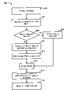
[00107] Reference is now made to Figure 14, which shows an example flow
diagram 800 of a method for joining a conference call in accordance with an
example embodiment. Reference is also made to the example interface 500 shown
in Figure 10 and the second interface 520 shown in Figure 11. The method shown
in Figure 13 is for joining a conference call from a communication device 11,
the
communication device 11 configured for being in a locked state or an unlocked
state. The memory 244 of the device 11 may include conference call scheduling
information with respect to a scheduled conference call, for example an
address link
or audio information for communicating with the enterprise communications
platform 14. At step 802, the method displays an interface 500 on the
communication device 11 while the communication device 11 is in the locked
state.
The interface 500 includes an option to join a scheduled conference call,
shown as
join now 510 (Figure 10). At step 804, by way of a user input device, the
device 11
receives an input for selection of the join now 510 option while the
communication
device 11 is in the locked state. At step 806, it is determined whether a
device
password is required to unlock the device 11. If so (if "yes"), the flow
diagram 800
proceeds to step 808 for receiving the device password. This includes
displaying a
password interface 516. The flow diagram 800 then proceeds to step 810 to
unlock
the device 11 to the unlocked state. In some example embodiments, if a
password
CA 02768789 2012-02-07
- 27 -
- is not required (if "no"), at step 812 an interface (e.g. interface
716 Figure 13) may
be displayed which prompts for an additional specified key sequence to be
input,
which may be required to prevent accidentally joining. For example and without
limitation, the interface may display the prompt to "Please enter 'ASTERISK
(*)
SEND' to join the conference call". At step 814, the specified key sequence is
received via user input. The flow diagram 800 then proceeds to step 810 to
unlock
the device 11.
[00108] At step 816, in response to the selection of the join now
510 option,
the device 11 sends a communication to the enterprise communications platform
14
for establishing a conference call session, using the contact information
stored in
memory 244. At step 818, the enterprise communications platform 14 answers the
communication and establishes a conference call session with the device 11.
[00109] In some other example embodiments, at step 806 if a
password is not
required (if "no"), the flow diagram 800 may proceed directly (not shown) to
step
810 to unlock the device 11, without the specified key sequence prompt.
[00110] Referring still to the flow diagram 800 of Figure 14,
note that, a similar
process can be followed with respect to the interface 600 shown in Figure 12.
For
example, the password interface 616 would be included within the same
interface
600 having the join now 610 option.
[00111] It can be appreciated that the specific words as shown in the
various
user interfaces are intended to be illustrative only. For example, any
suitable words
or phrases may be used, and would not be limited to the English language. For
example, any number of multi-lingual variations in different languages may be
displayed or output from the device.
[00112] Variations of the above example methods may be used. While some of
the above examples have been described as occurring in a particular order, it
will be
appreciated to persons skilled in the art that some of the messages or steps
or
processes may be performed in a different order provided that the result of
the
changed order of any given step will not prevent or impair the occurrence of
subsequent steps. Furthermore, some of the messages or steps described above
may be removed or combined in other embodiments, and some of the messages or
steps described above may be separated into a number of sub-messages or sub-
CA 02768789 2012-02-07
- 28 -
steps in other embodiments. Even further, some or all of the steps of the
conversations may be repeated, as necessary. Elements described as methods or
steps similarly apply to systems or subcomponents, and vice-versa.
[00113] For example, referring to Figure 10, the displaying of the
join now 510
option is not limited to the words "JOIN NOW", but can be any suitable text
such as
"MEET NOW". In other example embodiments, the join now 510 option displays the
actual link address (e.g. URL address) of the enterprise communications
platform 14
for joining the conference call.
[00114] Variations may be made to some example embodiments, which may
include combinations and sub-combinations of any of the above. The various
embodiments presented above are merely examples and are in no way meant to
limit the scope of this disclosure. Variations of the innovations described
herein will
be apparent to persons of ordinary skill in the art having the benefit of the
present
disclosure, such variations being within the intended scope of the present
disclosure.
In particular, features from one or more of the above-described embodiments
may
be selected to create alternative embodiments comprised of a sub-combination
of
features which may not be explicitly described above. In addition, features
from
one or more of the above-described embodiments may be selected and combined to
create alternative embodiments comprised of a combination of features which
may
not be explicitly described above. Features suitable for such combinations and
sub-
combinations would be readily apparent to persons skilled in the art upon
review of
the present disclosure as a whole. The subject matter described herein intends
to
cover and embrace all suitable changes in technology.