Note: Descriptions are shown in the official language in which they were submitted.
CA 02768872 2012-02-14
1
PACKAGES FOR ROLLED PRODUCTS
FIELD
The present disclosure generally relates to packages for rolled products and,
more
particularly, relates to large count packages for rolled products, such as
rolled fibrous products.
BACKGROUND
Rolled products or rolled absorbent or fibrous products such as paper towels,
toilet tissue,
disposable shop towels, and wipes, for example, are sometimes packaged and
shipped in bundles of
a plurality of rolls. The bundled packages often have two or more rolls
stacked in a side-by-side
fashion with another two or more rolls. Often, individually wrapped packages
of the two or more
rolls, or stacks of rolls, are packaged together into a larger "large count
package." In other
embodiments, large count packages can contain a plurality of "naked," (i.e.,
unwrapped) rolls of
product. The individually wrapped packages or naked rolls can be stacked or
positioned together
into a generally cuboid-shaped bundle and bound together with an overwrap.
Finished, overwrapped
large count packages can then be stacked on a pallet for shipping. Typical
pallets are designed to be
moved by fork lifts, are typically rectangular-shaped, and are usually about
three to about four and a
half feet long on each side. Such pallets are often also used in retail stores
for displaying the large
count packages of rolled products to consumers.
Pallets sizes, inside shipping truck dimensions, palletizing equipment,
packaging equipment,
and packaging processes can all place constraints on a manufacturer's ability
to innovate in the area
of packaging rolled products in a way that maximizes brand exposure to retail
customers while on
display in a retail store. Additionally, manufacturers desire to ship the
greatest amount of product in
the smallest amount of space in a form that ideally fulfills two goals:
convenient shipping and
handling and attractive shelf presence in a retail store that maximizes brand
exposure to retail
consumers.
Current packaging equipment and methodologies have certain limitations
relating to
optimizing shipping and retail presentation of rolled products. For example,
current equipment for
bundling naked rolls or individually wrapped packages of rolled products into
large count packages
of multiple rolls or multiple individually wrapped packages does so by
processing the rolls with the
rolled products in a vertical, stacked configuration (i.e., a longitudinal
axis of each core of each roll
is generally vertical). This is because the vertical orientation of the cores
offers weight bearing
structural support to the large count package in a vertical direction, which
allows for large count
CA 02768872 2012-02-14
2
package stacking and stacking of pallets of large court packages. The group of
vertically oriented
rolls is then processed through a bundler which applies an overwrap. The
overwrap is sealed with a
"gusset" seal on the leading and trailing sides of the group of the rolled
products.
Such gusset seals offer many advantages on large count packages for sealing
and handling
purposes, but they sometimes leave a poor visual appearance on the outer
perimeter of the large
count package by resulting in folds and creases of multiple layers of the
overwrap that block visual
aspects of the individually wrapped packages contained therein. Such folds and
creases can also
cover up or distort valuable branding information on the individually wrapped
packages.
Furthermore, gusset seals on the leading and trailing sides of the large count
package can inhibit the
full use of all of the area of the leading and trailing sides of the large
count package for advertising
or branding. In most instances, such advertising or branding may only be
printed on a portion of the
leading and trailing sides of the large count package owing to the positioning
of the gusset seals on
the leading and trailing sides. As a result, such positioning of the gusset
seals can decrease the
visual appeal of the leading and trailing sides when situated within a retail
store.
Furthermore, current equipment that bundles individually wrapped packages or
naked rolls
into large count packages has height limitations for the stacks of rolled
products. It would be
advantageous to be able to stack individually wrapped packages of rolled
products or naked rolls of
rolled products into relatively high stacks, in a large count package with a
relatively small footprint
(i.e., in what can be termed a "tower" version of large count packages).
Two problems can be associated with achieving higher stacks of rolled products
in a large
count package. First, the equipment (e.g., bundler) used to wrap the group of
individually wrapped
and stacked packages or naked rolls is limited in its height opening. Second,
even if the height
opening were made larger, the amount of polymer overwrap material associated
with the gusset seals
would become excessive, creating cost issues (with wasted polymer material),
potential safety issues
(with excess folds getting caught on adjacent objects), and aesthetic issues
(with multiple folds of
material bulging out and covering up or distorting the branded information on
the enclosed
individually wrapped packages of rolled products or decreasing the printable
area of the leading and
trailing sides of the large count package).
Therefore, there is a long-felt, unmet need for a way to manufacture large
count packages of
relatively high stacks of rolled products (i.e., tower versions).
CA 02768872 2012-02-14
3
Further, there is a long-felt, unmet need to make large count packages of
relatively high
stacks of rolled products, wherein each of the large count packages remains
stable when subjected to
side-to-side movement, shaking, and/or tilting during transport or otherwise.
Still further, there is along-felt, unmet need for large count packages of
individually wrapped
packages of two or more rolled products, wherein a gusset seal of the large
count package does not
significantly interfere with visibility of the branding indicia on the
individually wrapped packages
enclosed therein and/or does not significantly interfere with branding indicia
on the leading and
trailing sides of the large count packages.
SUMMARY
In one embodiment, the present disclosure is directed, in part, to a large
count package of
rolled products. The large count package comprises a generally cuboid shape
comprising six sides,
with the six sides arranged in three pairs of generally parallel opposing
sides. The large count
package comprises a film overwrap enclosing a plurality of individually
wrapped packages of rolled
products. Each package of the rolled products comprises at least two rolled
products and each rolled
product has a core defined therethrough. One of the first pair of opposing
sides is a top side and the
other of the first pair of opposing sides is a bottom side. One of the second
pair of opposing sides is
a front side and the other of the second pair of opposing sides is a back
side. One of the third pair of
opposing sides is a left side and the other of the third pair of opposing
sides is a right side. The
individually wrapped packages are disposed in the large count package with a
longitudinal axis of
each of the cores of each of the rolled products generally parallel with a
plane of each of the front,
back, left, and right sides. The overwrap is sealed with two seals. One seal
is disposed on each of
the top and bottom sides. The individually wrapped packages each comprise two
generally flat
sides. Each side has a plane that is positioned generally parallel to the
longitudinal axis of each of
the cores and that is positioned generally perpendicular to a longitudinal
axis of one of the seals.
In another embodiment, the present disclosure is directed, in part, to a
pallet comprising a
surface for supporting products. The pallet has four sides with each side
comprising an edge
positioned proximate to the surface. The edges define a perimeter of the
surface. The pallet
comprises a plurality of large count packages of rolled products supported by
the surface. Each of
the large count packages comprises the same or similar features as discussed
in the preceding
paragraph. Each of the large count packages is disposed on the surface such
that no portion of any
of the large count packages extends more than about 4 inches outside of the
perimeter of the surface.
The large count packages and the pallet are wrapped with a stabilizing film
such that the stabilizing
CA 02768872 2012-02-14
4
film wraps and stabilizes the large count packages and a portion of the
stabilizing film extends below
each edge and onto each pallet side.
In still another embodiment, the present disclosure is directed, in part, to a
pallet comprising
a plurality of large count packages supported on a surface thereof. Each of
the large count packages
comprises at least two individually wrapped packages of rolled products. Each
rolled product has a
hollow core defined therethrough. Each individually wrapped package of rolled
products comprises
at least two stacks of two rolls. The cores of each stack of two rolls are
generally parallel and
aligned and each adjacent stack of rolls lies generally in the same plane as
the other stack within the
individually wrapped package. The large count package comprises an overwrap of
film or polymer
film that encloses the individually wrapped packages of rolled products. The
overwrap is bound
with a seal on two sides. One of the seals is on a side supported by the
pallet and the other of the
seals is on the side opposite the side supported by the pallet. The
individually wrapped packages
each comprise two generally flat sides with each side having a plane that is
positioned generally
parallel to the longitudinal axis of each of the cores and that is positioned
transverse to a longitudinal
axis of one of the seals.
In yet another embodiment, the present disclosure is directed, in part, to a
method of
packaging a plurality of rolls of products having cores defined therethrough.
The method comprises
packaging at least two rolls together to form a first individually wrapped
package, packaging another
at least two rolls together to form a second individually wrapped package, and
positioning a
longitudinal axis of a core of each of the at least two rolls in the first
individually wrapped package
in a generally horizontal orientation generally in a machine direction on a
conveyor. The method
further comprises positioning a longitudinal axis of a core of each of the at
least two rolls in the
second individually wrapped package in a generally horizontal orientation
generally in the machine
direction on the conveyor, rotating the first individually wrapped package
into an upright position
where the longitudinal axis of the core of each of the at least two rolls in
the first individually
wrapped package is in a generally horizontal orientation, and rotating the
second individually
wrapped package into an upright position where the longitudinal axis of the
core of each of the at
least two rolls in the second individually wrapped package is in a generally
horizontal orientation.
The method further comprises positioning the first individually wrapped
package in a generally side-
by-side relationship with the second individually wrapped package, feeding the
first individually
wrapped package and the second individually wrapped package into a bundler,
applying an overwrap
around both of the first individually wrapped package and the second
individually wrapped package,
CA 02768872 2012-02-14
and forming seals on two vertically positioned sides created by a portion of
the first individually
wrapped package and a portion of the second individually wrapped package to
create a large count
package comprising the first individually wrapped package and the second
individually wrapped
package.
BRIEF DESCRIPTION OF THE DRAWINGS
The above-mentioned and other features and advantages of the present
disclosure, and the
manner of attaining them, will become more apparent and the disclosure itself
will be better
5 understood by reference to the following description of non-limiting
embodiments of the disclosure
taken in conjunction with the accompanying drawings, wherein:
Fig. 1 is a perspective view of a large count package for toilet tissue;
Fig. 2A is a front view of a large count package for paper towels;
Fig. 2B is a top view of the large count package of Fig. 2A;
Fig. 3 is a perspective view of a large count package in accordance with one
non-limiting
embodiment of the present disclosure;
Fig. 4A is a front view of a large count package in accordance with one non-
limiting
embodiment of the present disclosure;
Fig. 48 is a top view of the large count package of Fig. 4A in accordance with
one non-
limiting embodiment of the present disclosure;
Fig. 5 is a perspective view of an individually wrapped package in accordance
with one non-
limiting embodiment of the present disclosure;
Fig. 6 is a perspective view of another individually wrapped package in
accordance with one
non-limiting embodiment of the present disclosure;
Fig. 7 is a schematic illustration of a large count package, (B), in
accordance with one non-
limiting embodiment of the present disclosure, compared to a conventional
large count package (A);
Fig. 8 is a simplified perspective view of a pallet in accordance with one non-
limiting
embodiment of the present disclosure;
Fig. 9 is a simplified side view of a plurality of large count packages
positioned on a pallet in
accordance with one non-limiting embodiment of the present disclosure;
Fig. 10 is a process flow diagram for manufacturing large count packages in
accordance with
one non-limiting embodiment of the present disclosure;
CA 02768872 2012-02-14
s; . õ11 J,;01
71;444irrtie
'41 1/27,61.
=-
=.!! : 01111, - , 1' = '7
6
Fig. 11 is a cut away view taken along line 11-11 of Fig. 10, illustrating a
flipper mechanism
for flipping or rotating individually wrapped packages in accordance with one
non-limiting
embodiment of the present disclosure., and
Fig. 12 is a view of a large count package of the present disclosure
approaching an
orientation mechanism comprising a biasing bar in accordance with one non-
limiting embodiment of
the present disclosure. .
DETAILED DESCRIPTION
Various non-limiting embodiments of the present disclosure will now be
described to provide
an overall understanding of the principles of the structure, function,
manufacture, and use of the
large count packages for rolled products disclosed herein. One or more
examples of these non-
limiting embodiments are illustrated in the accompanying drawings. Those of
ordinary skill in the
art will understand that the large count packages for rolled products
specifically described herein and
illustrated in the accompanying drawings are non-limiting example embodiments
and that the scope
of the various non-limiting embodiments of the present disclosure are defined
solely by the claims.
The features illustrated or described in connection with one non-limiting
embodiment can be
combined with the features of other non-limiting embodiments. Such
modifications and variations
are intended to be included within the scope of the present disclosure.
Definitions
The term "cross direction" means the direction generally perpendicular to the
direction of
process flow of a product on a conveyor or assembly line (i.e., a direction
generally perpendicular to
a machine direction).
A "consumer" is the ultimate purchaser and/or user of the rolled product
within the Inge
count packages or within the individually wrapped packages of rolled product.
A "customer" is an entity that purchases large count packages or pallets of
large count
packages from a manufacturer with plans on selling the same to one or more
consumers.
The term "large count package" means a package comprising multiple
individually wrapped
packages of two or more rolled products or a plurality of naked rolls of
products enclosed, or at least
partially enclosed, in an overwrap, such as a film overwrap.
The term "machine direction" means the direction of process flow of a product
on a conveyor
or assembly line (i.e., a direction generally perpendicular to the cross
direction).
Disposable rolled products or disposable rolled absorbent products or
disposable rolled paper
products, such as paper towels, facial tissues, toilet tissues, shop towels,
wipes, and the like, are
CA 02768872 2012-02-14
7
generally made from one or more webs of fibers, such as cellulose fibers or
nonwoven fibers, for
example. If the fibrous products are to perform their intended tasks and to
find wide acceptance,
they, and the webs from which they are made, should usually exhibit certain
physical characteristics.
Among the more important of these characteristics are strength, softness, and
absorbency. Strength
is the ability of a fibrous web to retain its physical integrity during use.
Softness is a pleasing tactile
sensation the user perceives as the fibrous product is crumpled in their hand
and is contacted to
various portions of the anatomy. Absorbency is the characteristic of the
fibrous product that
facilitates the take up and retention of fluids, particularly water, aqueous
solutions, and/or
suspensions. Two important characteristics of a fibrous product include the
absolute quantity of a
to fluid the given amount of fibrous product will hold, but also the rate
at which the fibrous product
will absorb the fluid. When the fibrous product is formed into a paper towel,
toilet or facial tissue,
shop towel, and/or a wipe, for example, the ability of the fibrous product to
cause a fluid to
preferentially be taken up into the fibrous product and, thereby, leave a
wiped surface dry, or
substantially dry, is also important. "Rolled products" or "rolls of product"
or "rolls" within the
present disclosure can include products made from cellulose fibers, nonwoven
fibers, other suitable
fibers, and combinations thereof. In one embodiment, the rolled products can
be made of, or
partially made of recycled fibers.
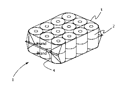
Referring to Fig. 1, in a conventional large count package 1 for toilet or
bath tissue rolls 2 or
multiples packages of the rolls 2, can be stacked two high vertically and then
feed into a bundler,
with a longitudinal axis of each core of each roll 2 being oriented in a
generally vertical direction.
The bundler is a piece of machinery that applies an overwrap 3 and creates
seals in the overwrap 3 to
form large count packages 1. The longitudinal axis of each core of each roll 2
is generally parallel to
a longitudinal axis of a core of another roll 2 in the stack of the rolls 2.
When the rolls 2 are fed into
the bundler in such an orientation, the overwrap 3 is positioned around the
stacks of the rolls 2 and
gusset seals 4 are formed on the leading and trailing sides in a horizontal
arrangement (i.e., a
direction generally parallel with a surface of a conveyor on which the large
count package 1 rests).
Such gusset seal locations may not be desirable to manufacturers, customers,
and/or consumers as
point-of-sale indicia, such as branding indicia, for example, on the overwrap
3 positioned on the
leading and trailing sides of the large count package 1, is usually limited to
the non-gusset seal areas
or less than about 70% of each of the leading and trailing sides. If ink is
printed on the overwrap 3
where the gusset seals 4 are to be formed, the gusset seals 4 may not be
formed properly, in that the
ink can adversely affect the formation of a heat seal bond used to form the
gusset seals 4.
CA 02768872 2012-02-14
8
Furthermore, using gusset seals 4 on the leading and trailing sides of the
conventional large count
package I can cause the overwrap 3 to bunch together and form creases therein,
sometimes leading
to a less than desirable aesthetic appearance for a customer and/or a
consumer. Additionally, such
configurations of large count packages are generally limited to one or three
rows of rolled product
high based on height dimension limitations of the bundler.
Referring to Fig. 2A and 28, a conventional large count package 5 for
individual rolls of
paper towels 6 is illustrated. Fig. 2A is a front view of the large count
package 5. Fig. 2B is a top
view of the large count package 5. In such a large count package 5, each
individual rolled paper
towel product 6 can be enclosed within an individually wrapped package (not
illustrated) and then
those paper towel products 6 can be packaged into the large count package 5.
In other embodiments,
the individual rolls of paper towel product may not be individually wrapped
and can instead be
"naked." In such embodiments, gusset seals 7 are positioned on the top and
bottom sides of the large
count package 5. The paper towel rolls 6 are usually only positioned two rows
high using "elevator"
technology. Elevator technology generally is technology that places one roll
of individually
wrapped paper towels 6 in a first row and a second roll of individually
wrapped paper towels 6 in a
second row that is on top of the first row before the individually wrapped
packages of paper towels 6
enter the bundler. In such an orientation, a longitudinal axis of each core of
each roll of paper towels
6 extends in a generally horizontal direction, in the machine direction. In
general, the large count
package 5 is usually only two rows high owing to the elevator technology being
capable of
supplying only a two roll stack of paper towels 6, the height restrictions of
the bundler, and because
of the individually packaged nature of each individually wrapped roll of paper
towels 6 (i.e., stability
issues).
Wrapping single rolls of toilet tissue to be positioned within a large count
package is
generally not desirable because of the give or looseness of the overwrap and
the possible relative
movement between the individually wrapped rolls, potentially leading to
stability issues of the large
count package. Also, consumers seem to desire that more than one roll of
toilet tissue is packaged
together for ease in distribution throughout a household or other premises.
Moreover, in some
instances, one or more individually wrapped rolls of toilet tissue can slide
or fall out of the generally
cuboid-shaped large count package, leading to various issues, including
unattractiveness of the large
count package when positioned within a retail store or other area. What is
more preferred is to wrap
two or more rolls of toilet tissue together and then position and align two or
more of those
individually wrapped packages of toilet tissue together and apply an overwrap
therearound to form a
CA 02768872 2012-02-14
9
large count package. Conventional techniques for packaging toilet tissue often
comprise packaging
two or more rolls of product together and orienting each of the rolls of
product with a longitudinal
axis of their respective cores in a vertical orientation when entering the
bundler. In such an instance,
gusset seals are formed on leading and trailing sides (in the machine
direction) of the large count
package. Various issues, as discussed herein, result from having gusset seals
positioned on the
leading and trailing sides of a large count package.
To provide better methods of packaging and better large count packages, the
present
disclosure provides, in part, large count packages for rolled products that
have seals or gusset seals
positioned on the top and bottom sides thereof instead of on the leading and
trailing sides (in a
to machine direction). The term "seals" can include any seals known to
those of skill in the art. Such
positioning of the seals or gusset seals results in a plane of the top and
bottom sides of the large
count packages to be situated generally perpendicular to a longitudinal axis
of a core of each roll
within the large count packages. The present disclosure also contemplates a
method of
manufacturing the large count packages and pallets of large count packages,
such as shipping and
display pallets. Various benefits of the large count packages of the present
disclosure are discussed
herein. The large count packages of the present disclosure can be sold in club
stores, supermarkets,
department stores, warehouses, discount outlets, and/or convenience stores,
for example.
In one embodiment, referring to Fig. 3, a large count package 10 encased in an
overwrap 12
of sealed or unsealed polymer film, or other film or material, can comprise
seals or gusset seals 14
on top and bottom sides thereof (bottom seal or gusset seal not illustrated).
The overwrap 12 can
hold individually wrapped packages 16 of at least two rolls of product
together to form the large
count package 10 into a rectangular cuboid shape or cuboid shape and add to
its stability. Each roll
of product can be wound about a paper, cardboard, paperboard, or corrugate
tube to form a core
through each roll. Each core can define a longitudinal axis extending
therethrough. In other various
embodiments, the rolls of product may not comprise the paper, cardboard,
paperboard, or corrugate
tube, but instead the product can be wound about itself to form a roll while
still forming a core
defined through each roll. The void area in the center of each roll where the
product winds about
itself can be considered a "core" for purposes of this disclosure and the
claims. Such rolls are
known in the art as "coreless" rolls. In such embodiments, the same principals
of the present
disclosure, including the orientation of the rolls within the various
individually wrapped packages
and large count packages, can be applied to "coreless" rolls.
CA 02768872 2012-02-14
In one embodiment, referring to Fig. 3, the large count package 10 comprises
18 rolls of the
rolled product, but, the present disclosure is not limited to such a number of
rolls within a large
count package. In fact, any suitable number of rolls equal to or greater than
4 can be combined into
a large count package. In various example embodiments, a large count package
can comprise 6
5
rolls, 8 rolls, 9 rolls, 12 rolls, 16 rolls, 18 rolls, 20 rolls, 24 rolls, 27
rolls, 30 rolls, 32 rolls, 36 rolls,
40 rolls, 45 rolls, 48 rolls, 54 rolls, 60 rolls, or 72 rolls, for example, or
any other suitable number of
rolls. The method of packaging a large count package of the present disclosure
permits greater
flexibility in the number of rolls and configurations of rolls that can be
provided in a specific large
count package.
10
In various embodiments, referring to Figs. 4A and 4B, a large count package
10' encased in
an overwrap 12' optionally of a sealed polymer film can comprise seals 14',
such as gusset seals, for
example, on top and bottom sides thereof is illustrated. Fig. 4A is a front
view of the large count
package 10' and Fig. 4B is a top view of the large count package 10'. The
large count package 10'
comprises 48 rolls of rolled products. In various embodiments, when viewing a
top side (Fig. 4B) of
the large count package 10', the number of rolls of product in a first
direction can be greater than a
number of rolls of product in a second direction to provide stability to the
large count package 10'.
Stated another way, a top side and a bottom side of the large count package
10' can be rectangular.
In other various embodiments, the top and bottom sides can be square or can be
any other suitable
shape.
In various embodiments, referring again to Fig. 3, the large count package 10
can have a
generally cuboid shape, a generally rectangular cuboid shape, or any other
suitable shape. In an
embodiment where the large count package 10 has a generally rectangular cuboid
shape, or a cuboid
shape, the large count package 10 can comprise six sides. The sides can be
arranged in three pairs of
generally parallel opposing sides. A first pair of the opposing sides can be a
top side and a bottom
side. A second pair of the opposing sides can be a front side and a back side.
A third pair of the
opposing side can be a left side and a right side. Point-of-sale indicia
(i.e., branding materials, other
indicia, and/or other materials that a consumer sees when purchasing a product
at a retail store) can
be printed or positioned on any of the top, bottom, front, back, left, and
right sides. In other various
embodiments, such indicia or other materials may only be printed or positioned
on the top, front,
back, left, and right sides, for example. In still other various embodiments,
such indicia or other
materials can be printed or positioned on one or more sides of the large count
package 10.
CA 02768872 2012-02-14
11
In one embodiment, referring generally to Fig. 3, for example, the large count
package 10
can comprise two or more individually wrapped packages 16 of rolls of product.
Each individually
wrapped package 16 can comprise at least two stacks of at least two rolled
products. A longitudinal
axis of each of the cores of each stack of at least two rolls can be generally
parallel and aligned with
each other and adjacent stack(s) of at least two rolls can lie in generally
the same plane as the other
stack(s) of at least two rolled products. All individually wrapped packages
will be referred to herein
as "16," although some individually wrapped packages will have a different
number of rolls of rolled
product therein. In various embodiments, the individually wrapped packages 16
can each comprise
two or more rolls of product, such as two, three, four, six, eight, nine, ten,
twelve, or fifteen rolls of
product, for example. Those of skill in the art will recognize that other
numbers of rolls of product
can be useful in individually wrapped packages depending on a desired
configuration of a particular
large count package or a consumer need. The two or more rolls of product can
be stacked on top of
each other and each stack can be positioned adjacent to another stack within
the individually
wrapped package 16. In such an embodiment, a longitudinal axis of each of the
cores of the two or
more rolls of product in each stack can be generally parallel and aligned and
each stack can be in the
same plane, or in generally the same plane, as each adjacent stack. In other
various embodiments,
the two or more rolls of product can be positioned generally in a side-by-side
fashion with respect to
each other within the individually wrapped package 16. In one embodiment,
referring to Fig. 5, the
individually wrapped package 16 can comprise four rolls of product and can
comprise a seal 17,
such as an envelope seal, for example, formed thereon. In another embodiment,
referring to Fig. 6,
the individually wrapped package 16 can comprise nine rolls of product
(envelope seal or other seal
not illustrated). Multiple rolls of product can be enclosed and/or sealed in a
polymer film or other
suitable material to form the individually wrapped packages 16.
In one embodiment, referring to Figs. 3-6, the individually wrapped packages
16 can each
comprise a first side 18 and a second side 20 which can each have planes that
are positioned
generally perpendicular (between axes 21 of the planes) to a longitudinal axis
22 of the seal or gusset
seal 14 or of both of the seals or gusset seals 14. In one embodiment, a plane
of the first side 18 and
the second side 20 can each intersect, in a generally perpendicular fashion,
with the longitudinal axis
22 of the seals or gusset seals 14. Point-of-sale indicia 19 (Figs. 5 and 6)
can be positioned on or
printed on the first side 18 and/or the second side 20. Such point-of-sale
indicia 19 can be visible
through the overwrap 12 through at least one side of the large count package
10. In various
embodiments, two or more, such as three, for example, individually wrapped
packages 16 can be
CA 02768872 2012-02-14
12
positioned within the large count package 10. Each individually wrapped
package 16 can comprise
at least two vertically oriented stacks of rolled products. In one embodiment,
the first side 18 and
the second side 20 of each individually wrapped package 16 can have generally
flat sides having
planes positioned generally parallel with the longitudinal axis of each of the
cores, wherein the first
and second sides 18 and 20 can comprise point-of-sale indicia, branding
indicia, and/or other
materials. The individually wrapped packages 16 can be oriented within the
large count package 10
such that at least on one side of the large count package 10 such indicia or
other materials are visible
through the overwrap 12. In various embodiments, the individually wrapped
packages 16, or
portions thereof, are viewable through the overwrap 12 from a position outside
of the large count
package 10.
In various embodiments, referring to Fig. 7, the first and second sides 18 and
20 of the
individually wrapped packages 16 not forming an outer perimeter of a large
count package can be
positioned adjacent to each other or generally in a side-by-side relationship.
In fact, the first and
second sides 18 and 20 of the individually wrapped packages 16 can be
positioned generally in a
face-to-face relationship within the large count package, with the exception
of those first and second
sides 18 and 20 that form a portion of the outer perimeter of the large count
package (i.e., the
individually wrapped packages 16 on the ends of the large count package). In
Fig. 7, large count
package B is more stable than large count package A owing to the orientation
and packaging of the
individually wrapped packages 16 within the large count packages A and B. When
both of the large
count packages A and B are pushed or moved in the directions indicated by
arrow C, the large count
package A is about as stable as the large count package B because both of the
large count packages
A and B comprise bases that are three rolls wide. When both of the large count
packages A and B
are pushed or moved in the directions indicated by arrow D, however, the large
count package B is
much more stable than the large count package A, as the large count package A
comprises two
individually wrapped packages 16' that can move and/or slide relative to each
other. Stated another
way, the two individually wrapped packages 16' in the large count package A
essentially form two
plate-like structures that can slide or move relative to one another. If the
large count package A is
put on an angled or inclined floor, one of the individually wrapped packages
16' will likely fall or
move lower than the other, thereby increasing the likelihood of the overall
large count package A
falling over. The large count package B, however, of the present disclosure,
is quite stable if moved
in the directions indicated by arrow D or if positioned on an angled or
inclined floor owing to the
configuration and packaging of the three individually wrapped packages 16 that
create a two roll
CA 02768872 2012-02-14
13
deep base bound together, verses a two roll deep base not bound together as
created by the
individually wrapped packages 16' of the large count package A.
In various embodiments, still referring to Fig. 7, the large count package B
can resist tipping
over or have a greater "tipping angle" than the large count package A owing to
the configuration
and/or orientation of the individually wrapped packages 16 within the large
count package B, as
compared to the configuration and/or orientation of the individually wrapped
packages 16' within
the large count package A. The tipping angle is the angle at which a large
count package will fall
over onto its side (verses sitting on its base or bottom side), if pushed or
moved in the directions
indicated by arrow D and/or if acted upon by forces of gravity when the base
is on an inclined
surface. The tipping angle can be measured between the inclined surface that a
large count package
is positioned on and the horizontal. The large count package A will tip over
easier than the large
count package B, when pushed or moved in the directions indicated by arrow D,
or if positioned on
an inclined surface, owing to the configuration and orientation of the
individually wrapped packages
16 and 16'.
The tipping angle for the large count package A can vary based on factors such
as large count
package dimensions, roll diameters, roll lengths, compressibility of the
rolled products, and/or
tightness of the overwrap around the individual packages of two or more rolled
of products, for
example.
In one embodiment, referring again to Fig. 7, large count packages can have
extra material in
the overwrap. Stated another way, the overwrap can fit loosely around the
individually wrapped
packages 16 and 16' within the large count packages A and B. By providing the
individually
wrapped packages 16 in the orientation illustrated in large count package B,
this loose fit of the
overwrap will not have any significant adverse influence on the stability of
the individually wrapped
packages 16 within large count package B owing to their orientation. A loose
overlap on large count
package A, however, can have an adverse influence on the stability of the
individually wrapped
packages 16' within large count package A in that the individually wrapped
packages 16' can more
easily slide relative to each other owing to their configuration (thereby
reducing stability in the D
directions). It is important to note that the orientation of the individually
wrapped packages 16
within large count package B provides improved stability to the large count
package B when pushed
in the D directions (see arrow in Fig. 7) when compared to large count package
A. In fact, large
count package A can have reduced stability when pushed in the D directions,
while large count
package B can have suitable stability when pushed in the D directions.
CA 02768872 2012-02-14
14
The large count package A can have seals or gusset seals formed on top and
bottom sides
thereof. The large count package A can be formed, for example, by providing
two individually
wrapped packages of 3 rolls wide, by 3 rolls wide, by 1 roll deep (i.e., nine
roll individually wrapped
packages). A first individually wrapped package of nine rolls can be
positioned on top of a second
individually wrapped package of nine rolls before the packages are conveyed
into a bundler. In such
an orientation, the longitudinal axis of each roll in each of the first and
second individually wrapped
packages 16' is positioned generally horizontally. The first individually
wrapped package can be
positioned on top of the second individually wrapped package using elevator
technology. The
incorporation of elevator technology into production lines, however, is quite
expensive (e.g.,
sometimes in the nature of millions of dollars per manufacturing line),
thereby somewhat limiting its
use. Furthermore, the elevator technology limits the configurations and
orientations of large count
packages that a manufacturing facility can produce when compared to the
technology of the present
disclosure.
Through the advancements taught by the present disclosure, more large count
packages can
be positioned on and/or supported by a pallet owing to the ability to now
produce stable "tower"
configuration large count packages having a smaller "footprint" or base than
conventional large
count packages 1 (see e.g., Fig. 1). Previously, a 24 roll large count package
generally was 3 rolls
wide, by 4 rolls deep, by two rolls high (i.e., two layers of 12 rolls). As
mentioned herein, a typical
bundler can usually only accept heights of two or three rolls high, thereby
limiting the configurations
available for previous large count packages. Stated another way, previous
large count packages
were limited to a two or three roll height and seals or gusset seals were
formed on the leading and
trailing sides of the large count package. With the technology of the present
disclosure, however, a
24 roll large count package can be 3 rolls wide, by 2 rolls deep (the limited
dimension), by 4 rolls
high owing to the fact that the height of large count packages 10 is not
longer limited. The size of
the large count package can now also be doubled to a 48 roll large count
package by making the
large count package 4 rolls wide, by 3 rolls deep, by 4 rolls high. Previous
technology for making
48 roll large count packages would not permit such a large count package to be
made because of
pallet spacing issues and bundler height limitations. As a result, not only do
the methods of
packaging large count packages of the present disclosure allow for a reduced
footprint of a large
count package on a pallet, but they also allow manufacturers to make large
count package
configurations that were previously not possible.
CA 02768872 2012-02-14
One difference in the present large count packaging methods is that a
longitudinal axis of
each core of each rolled product within an individually wrapped package is now
positioned generally
horizontally when it enters the bundler and when the bundler applies the
overwrap therearound, as
compared to the longitudinal axis of each of the cores of the rolled product
being positioned
5 generally vertically upon entry into the bundler. Stated another way, the
maximum height a bundler
can accept is no longer limiting to the configuration of large count packages
being produced. As
such, tower packs can now be produced where only the depth of the rolls of the
large count package
is limited to the maximum height of the bundler. As a result, although the
depth height is limited by
the bundler, tower large count packages can be produced that are easier to
handle, ship, transport by
10 consumers, and/or store. Previous large count packages, such as 60 roll
large count packages, were
often hard to handle, ship, transport, and/or store by consumers owing to
their large, short,
rectangular configuration.
A typical pallet 30, such as a shipping and/or display pallet, for example, is
illustrated in Fig.
8. The pallet 30 can be rectangular, for example. As known to those of skill
in the art, a rectangle
15 can include a square. In one embodiment, the pallet 30 can comprise four
sides 32, each side 32
comprising an edge 34 positioned adjacent to a pallet surface 31, wherein the
edges 34 together form
a surface perimeter. The surface 31 can be configured to receive or support
the large count packages
10. In one embodiment, a material, such a paperboard, for example, can be
positioned on the surface
31 to protect the large count packages from damage. Due to safety and product
damage reasons, any
large count package 10 on the pallet 30 may not usually extend more than about
4 inches outside of
the surface perimeter or hang over any of the edges 34 by more than about 4
inches. In other
embodiments, the large count packages 10 may not extend more than 3 inches, 2
inches, 1 inch, or at
all from the surface perimeter defined by the edges 34.
In one embodiment, referring to Fig. 9, the pallet 30 can be loaded with one
or more of the
large count packages 10. In various embodiments, the sides 36 of the large
count packages 10 can
have more than about 85% coverage of branding indicia, point-of-sale indicia,
other indicia, and/or
other materials owing to the fact that the seals or gusset seals 14 are
positioned on the top and
bottom sides of the large count packages 10. In another embodiment, such
indicia or materials can
cover from greater than 85% to about 100%, specifically reciting every one
percent therebetween, of
the surface area of each of the sides 36 of the large count packages 10. By
providing the large count
packages 10 of the present disclosure, more side wall surface area can be used
more fully to promote
branding or product benefits, thereby adding to the overall aesthetic
appearance of the large count
CA 02768872 2012-02-14
16
packages 10. End walls (not illustrated in Fig. 9) of the large count packages
10 can also be used for
branding or other printed material because of the positioning of the seals or
gusset seals 14 on the
top and bottom sides of the large count packages 10. In one embodiment, the
sides 32 of the pallet
30 may also comprise branding or other printed material. The pallet 30 and the
large count packages
10 supported thereon can be wrapped with a stabilizing film (not illustrated),
such as stretch wrap,
for example, that extends below each edge 34 (see Fig. 8) and onto each pallet
side 32. The
stabilizing film can be used to maintain the large count packages 10 on the
pallet 30 and to hold the
large count packages 10 together.
In one embodiment, a method of packaging a plurality of rolled products is
provided.
Referring to Fig. 10, the method can comprise packaging at least two rolled
products together in an
individually wrapped package 16. Multiple individually wrapped packages 16 can
be prepared, such
as two, three, four, five, six, eight, nine, ten, or twelve, for example. The
individually wrapped
packages 16 can be the same as any of the individually wrapped packages 16
described above. The
individually wrapped packages 16 can then be positioned on or conveyed to a
conveyor 40, such as a
ts set of rollers or a continuous belt, for example. When on the conveyor
40, one of the first side 18
and the second side 20 of each of the individually wrapped packages 16 can
rest on the conveyor 40,
with the other of the first side 18 and the second side 20 of each of the
individually wrapped
packages 16 facing away from the conveyor 40. In general, the first side 18
and the second side 20
can each have a larger surface area than the other four sides (i.e., two other
side walls and two end
walls) of the individually wrapped packages 16. The longitudinal axis
(indicated by dashed lines) of
each core of each roll can be positioned generally horizontally generally in
the machine direction (as
indicated by arrow E) and more than one stack of rows of rolled products can
be supported by the
conveyor 40. Each of the individually wrapped packages 16 can then be flipped
or rotated about 90
degrees in a cross-direction (i.e., a direction generally perpendicular to the
direction indicated by
arrow E) to an upright position where the longitudinal axis of each core of
each roll is positioned
horizontally, still generally in the machine direction, and one stack of rows
(i.e., a side wall other
than the first side 18 and the second side 20) can be supported by the
conveyor 40. Those of skill in
the art will recognize that, with individually wrapped packages 16 comprising
more than one row in
depth, the conveyor 40 can support two or more rows in a similar upright
orientation. After the
individually wrapped packages 16 are flipped or rotated about 90 degrees,
generally in the cross
direction into an upright position, each individually wrapped package 16 can
be conveyed or moved
between guide rails 38 or other structures to maintain the generally upright
positioning of the
CA 02768872 2012-02-14
17
individually wrapped packages 16 when they enter a bundler 42. Once inside the
bundler 42, the
multiple individually wrapped packages 16 can be bundled together with the
overwrap 12 to create
one of the large count packages 10 of the present disclosure. The overwrap 12
can be sealed using
seals or gusset seals 14, on the leading and trailing sides of the newly
formed large count package
10. During bundling, the longitudinal axis of each core of each roll can be
positioned generally
horizontally generally in the machine direction (as indicated by arrow E). The
large count package
can then be moved or conveyed out of the bundler 42.
In one embodiment, when the large count package 10 exits the bundler 42, the
longitudinal
axis of each core of each roll can be positioned generally horizontally
generally in the machine
10 direction. The large count package 10 can then be flipped or rotated
about 90 degrees in or opposite
to the machine direction into an orientation in which tha longitudinal axis of
each of the cores of the
rolls is in a generally vertical orientation. As such, the gusset seals 14, or
other seals, on the large
count package 10 are now positioned on the top and bottom sides of the large
count package 10 as
the large count package 10 rests on, or is supported by, the conveyor 40.
Stated another way, the
leading and trailing sides of the large count package 10 can be rotated into a
position where they
form the top and bottom sides of the large count package 10. In other
embodiments, the large count
package 10 can be flipped or rotated about 90 degrees in or opposite to the
machine direction while
within the bundler 42, but after application of the overwrap 12. The large
count package 10 can then
be conveyed or moved away from the bundler 42 for loading onto a pallet or
direct shipping, for
example.
In one embodiment, referring to Fig. 11, example flipper mechanisms 44 for
flipping or
rotating the individually wrapped packages 16 into an upright position are
illustrated. The cross-
sectional view of Fig. 11, taken about line 11-11 of Fig. 10, also illustrates
a roller 43 about which
the conveyor 40 can travel. The flipper mechanisms 44 can each comprise a
support member 46 and
a flipper 48. In one embodiment, the flipper 48 can be attached to the support
member 46 such that
the flipper 48 is held in a particular position or orientation. The flipper 48
can be movable with
respect to the support member 46. In one embodiment, the flipper 48 can be
operably engaged with
the support member 46 such that the flipper 48 can move upwards and downwards
with respect to
the support member 46. Such movement of the flipper 48 can permit flipping or
rotating of the
individually wrapped packages 16 into an upright position. The flipping or
rotating can occur
generally in the cross direction. In one embodiment, the flipper 48 can
comprise a high coefficient
of friction material or surface, small projections, an adhesive material,
and/or a tack material, for
CA 02768872 2012-02-14
18
example, to help enable the flipper 48 to engage and flip the individually
wrapped packages 16.
Upon approach of an individually wrapped package 16 on the conveyor 40, the
flipper 48 can be in a
first position proximate to a surface of the conveyor 40. Once the
individually wrapped package 16
is conveyed into a position in which at least a portion of the flipper 48 is
underneath or engages at
least a portion of the individually wrapped package 16, the flipper 48 can be
moved, likely by
automated movement, into a second position distal from the surface of the
conveyor 40. Such
movement by the flipper 48 can cause the individually wrapped package 16 to be
rotated between
about 70 and about 110 degrees (and specifically reciting each degree within
that range) and
alternatively about 90 degrees into the upright position. hi one embodiment,
although not illustrated,
a flipper mechanism can comprise a support member and a flipper, wherein the
flipper is rotatably or
pivotably engaged with the support member and can move relative to the support
member 46 by
rotational or pivotal movement. When the flipper is rotated or pivoted
relative to the support
member, an individually wrapped package 16 can be moved from a position in
which one of the first
side 18 and the second side 20 is supported by the conveyor 40 into an upright
position in which one
of the other sides is supported by the conveyor 40. Those of skill in the art
will recognize various
alternative approaches to flipping or rotating the individually wrapped
packages 16 of the present
disclosure into an upright position, such as flipping or rotating by hand,
rotation or flipping via
gravity, and/or rotation or flipping by movement or tilting of a conveyor in a
machine direction or a
cross direction, for example. As such, the present disclosure is not limited
to the examples set forth
herein.
In one embodiment, referring to Fig. 12, after the overwrap 12 is applied to
the individually
wrapped packages 16 to form the large count package 10, the large count
package 10 can have each
longitudinal axis of each roll of product positioned generally horizontally
generally in the machine
direction. In one example, after the large count package 10 is moved or
conveyed out of the bundler
42, it may be desirable to flip or rotate the large count package 10 about 90
degrees into a position in
which each longitudinal axis of each core of each roll of product is generally
in a vertical direction.
The rotating or flipping can generally occur in the machine direction, in a
direction opposite the
machine direction, or in a direction generally perpendicular to the cross
direction. In one
embodiment, an orientation mechanism 50 can comprise one or more supports 52
and a biasing bar
54. The biasing bar 54 can be operatively engaged with the supports 52 (or one
support) such that
the biasing bar 54 is moveable relative to the supports 52. In other
embodiments, the biasing bar 54
can be stationary relative to the supports 52 in configurations of large count
packages 10 that can fit
CA 02768872 2012-02-14
19
under the biasing bar 54 once the large count packages 10 are flipped or
rotated. The biasing bar 54
can initially be positioned a first distance away from the surface of the
conveyor 40 when the large
count package 10 is approaching on the conveyor 40. The biasing bar 54 can
remain in such a
position at least until it is contacted by the leading side of the large count
package 10. In one
embodiment, the biasing bar 54 can contact the leading side of the large count
package 10 on a
portion of the leading side above a plane extending horizontally from the
center of gravity of the
large count package 10 to aid in rotation of the large count package 10. Upon
contact between the
biasing bar 54 and the leading side of the large count package 10, the large
count package 10 can
begin to be rotated about 90 degrees in a direction generally opposite to the
machine direction into a
position in which a longitudinal axis of each core of each roll of product is
in a generally vertical
position. A sufficient coefficient of friction can exist between the surface
of the conveyor 40 and a
portion or side of the large count package 10 contacting the conveyor 40 to
allow such flipping or
rotation of the large count package 10. The biasing bar 54 can remain at the
same position (i.e., the
same distance away from the surface of the conveyor 40), or can move upwardly
during contact with
the leading side of the large count package 40. Whether the biasing bar 54
remains stationary or
moves upwardly (i.e., away from the surface of the conveyor 40) may depend on
the size and shape
of the large count package 10 and/or on the number of rolls and/or stacks of
rolls within the large
count package 10. Depending on the height of the large count package 10 (i.e.,
the distance from the
surface of the conveyor 40 to the top side of the large count package 10 when
a longitudinal axis of
each core of each roll is in the vertical position), the biasing bar 54 may or
may not need to move
upwards relative to the surface of the conveyor 40 so that the large count
package 10 can pass on the
conveyor 40 below the biasing bar 54 after the rotation. In one embodiment,
the large count package
10 can be flipped or rotated into a position in which a longitudinal axis of
each core of each roll is in
the vertical position by hand. Those of skill in the art will recognize
various alternative approaches
to flipping or rotating the large count packages of the present disclosure,
such as flipping or rotating
by hand, rotation or flipping via gravity, and/or rotation or flipping by
movement or tilting of a
conveyor in a machine direction or a cross direction, for example. As such,
the present disclosure is
not limited to the examples set forth above.
In one embodiment, the biasing bar 54 can comprise features that allow it to
temporarily
engage and/or temporarily grip a portion of the leading side of the large
count package 10 to enable
or assist the rotation or flipping. As used in the sentence above, the term
"temporarily" can mean
during contact or during a portion of the contact between a portion of the
biasing bar 54 and a
CA 02768872 2012-02-14
portion of the large count package 10. In one embodiment, the biasing bar 54
may comprise a
plurality of pins or other elongate projections (not illustrated) extending
therefrom that can pierce
small holes in portions of the leading side of the large count package 10 or
the overwrap 12 when the
large count package 10 approaches and contacts the pins or elongate
projections. The pins or
5 elongate projections, through their engagement with the large count package
12, can allow the
biasing bar 54 to essentially grip the large count package 10 for rotation or
flipping. In one
embodiment, the pins or elongate portions can have a length in the range of
about 0.1 inches to about
3 inches, specifically reciting all 0.1 inch increments therebetween. In other
embodiments, the
biasing bar 54 can comprise an adhesive material, a tack material, and/or a
high coefficient of
10 friction material or surface to allow temporary engagement between a
portion of the large count
package 10 and the biasing bar 54 during flipping or rotation. Those of skill
in the art will recognize
various alternative approaches to temporarily gripping or engaging a portion
of the large count
package 10 for flipping or rotation. As such, the present disclosure is not
limited to the examples set
forth above.
15 In one embodiment, a method of packaging a plurality of rolls of
products can comprise
packaging at least two rolls together to form a first individually wrapped
package, packaging another
at least two rolls together to form a second individually wrapped package,
positioning a longitudinal
axis of a core of each of the at least two rolls in the first package. in a
generally horizontal orientation
generally in a machine direction on a conveyor, and positioning a longitudinal
axis of a core of each
20 of the at least two rolls in the second package in a generally
horizontal orientation generally in the
machine direction on the conveyor. The method can further comprise rotating
the first individually
wrapped package into an upright position where the longitudinal axis of the
core of each of the at
least two rolls in the first package is in a generally horizontal orientation,
rotating the second
individually wrapped package into an upright position where the longitudinal
axis of the core of each
of the at least two rolls in the second package is in a generally horizontal
orientation, and positioning
the first individually wrapped package in a generally side-by-side
relationship with the second
individually wrapped package. The method can further comprise feeding the
first individually
wrapped package and the second individually wrapped package into a bundler,
applying an overvvrap
around both of the first individually wrapped package and the second
individually wrapped package,
and forming seals or gusset seals on two vertically positioned sides created
by a portion of the first
individually wrapped package and a portion of the second individually wrapped
package to create a
large count package comprising the first individually wrapped package and the
second individually
CA 02768872 2014-03-03
21
wrapped package. The steps recited in this paragraph can be performed in
sequential order or in
other orders. The method can further comprise rotating the large count package
about 90 degrees
after the seals or gusset seals are formed such that the longitudinal axis of
each core of each roll in
both the first individually wrapped package and the second individually
wrapped package is in a
generally vertical orientation. The large count package can then be positioned
on a pallet for
shipping, transport, storage, and/or display in a retail environment.
In one embodiment, the large count packages 10 of the present disclosure can
comprise a
handle or handle portion (hereafter handle). The handle can be formed with a
portion of the
overwrap 12 or can be formed of a separate component and attached to the
overwrap 12. In various
embodiments, the handle can be formed in one or more portions of the seals or
gusset seals 14 or a
separate handle can be attached to portions of one or more of the seals or
gusset seals 14. Various
handles and handle configurations and orientations are illustrated in U.S.
Publication No. 2012-
0145733, filed December 14, 2010, entitled, PACKAGE WITH HANDLE. Those of
skill in the art
will recognize that other handles and handle configuration can be used with
the large count packages
10 of the present disclosure.
The dimensions and values disclosed herein are not to be understood as being
strictly limited
to the exact numerical values recited. Instead, unless otherwise specified,
each such dimension is
intended to mean both the recited value and a functionally equivalent range
surrounding that value.
For example, a dimension disclosed as "40 mm" is intended to mean "about 40
mm."
The citation of any document, including any cross referenced or related
patents or patent
applications, is not an admission that it is prior art with respect to any
invention disclosed or claimed
herein or that it alone, or in any combination with any other reference or
references, teaches,
suggests or discloses any such invention. Further, to the extent that any
meaning or definition of a
term in this document conflicts with any meaning or definition of the same
term in a document cited
herein, the meaning or definition assigned to that term in this document shall
govern.
While particular embodiments of the present invention have been illustrated
and described, it
would be obvious to those skilled in the art that various other changes and
modifications can be
made without departing from the invention described herein. The scope of the
claims should not be
limited to the preferred embodiments but should be given the broadest
interpretation consistent with
the description as a whole.