Note: Descriptions are shown in the official language in which they were submitted.
PRE-NOTCHED DRIP EDGE ASSEMBLY AND METHOD
BACKGROUND OF THE INVENTION
The present invention relates to drip edges for building roofs and the like,
and in
particular, to a pre-notched drip edge assembly and related method which is
easy to
install and improves alignment between the adjacent drip edge sections.
Drip rails or edges are well known in the building industry, and typically
comprise
L-shaped sheet metal strips which are installed along the bottom edge of a
roof to
prevent rainwater and/or snow melt from leaking under the shingles or other
roofing
media. Without such protection around the perimeter of the building roof,
capillary
action between the roofing material and the roof structure, as well as high
winds and
other environmental conditions, will result in moisture collecting on the
building
structure, which ultimately results in leaks and degradation of the integrity
of the roof.
Most prior drip edge strips have a flat folded over nose which interconnects
the
top and bottom flanges, and protrudes outwardly to direct rainwater away from
the
associated building. An elongate strip of sheet metal or the like is first
roll formed or
otherwise formed to shape, and then cut off into a plurality of individual
drip edge
sections. During the cut off process, the nose portions of the drip edge
sections are
completely closed, which makes it difficult, if not impossible, to quickly
assemble and
align the same along the edge of the building roof. Heretofore, the ends of
the drip edge
sections are nested within one another at each joint so as to ensure a
continuous barrier
along the building roof edge. This nesting assembly is relatively difficult
when the noses
of the drip edge sections are completely closed, and can lead to bending the
drip edge
sections out of shape, which can also cause misalignment between the adjacent
drip
edge sections. Accordingly, there exists the need for an improved drip edge
assembly,
which addresses these concerns in a cost effective manner.
SUMMARY OF THE INVENTION
One aspect of the present invention is a pre-notched drip edge assembly for
building roofs, comprising a plurality of elongate drip edge sections having
opposite
ends interconnected in an end-to-end relationship to form a continuous
rainwater
barrier along an associated building roof edge. Each of the drip edge sections
has a
formed one-piece construction which includes a top flange portion normally
oriented
generally horizontally and having a forward edge area. Each drip edge section
also has a
1
CA 2768934 2018-11-05
CA 02768934 2012-02-23
front flange portion having an inverted generally L-shaped configuration with
a lower leg
,
A normally oriented generally vertically and having an upper edge area,
and an upper leg
oriented generally horizontally and having a forward edge area. The forward
edge area
of the top flange portion and the forward edge area of the upper leg are
integrally
interconnected along a folded-over nose portion having a generally wedge-shape
side
elevational configuration which projects outwardly from the lower leg and
extends
longitudinally along the drip edge section to deflect rainwater away from the
building.
Each of the drip edge sections also has a pair of notches formed in opposite
ends
thereof, which extend a preselected distance through the upper edge area of
the lower
leg, the forward edge area of the upper leg and the forward edge area of the
top flange
portion, thereby defining generally flat end tab areas on the top flange
portion that are
inserted into the folded-over nose portion of the next adjacent one of the
drip edge
sections to horizontally and vertically locate the same for end-to-end
interconnection of
the drip edge sections along the building roof.
Another aspect of the present invention is a method for making a pre-notched
drip edge assembly for building roofs of the type having a plurality of
elongate drip edge
sections with opposite ends interconnected in an end-to-end relationship to
form a
continuous rainwater barrier along an associated building roof edge. The
method
comprises selecting an elongate strip of formable material having a length
sufficient to
construct a plurality of the drip edge sections therefrom. The method also
includes
forming a plurality of substantially identical through windows in the strip in
a
longitudinally aligned and longitudinally spaced apart relationship. After the
window
forming step, the method also includes forming a top flange in the strip that
is normally
oriented generally horizontally and has a forward edge area, and also forming
a front
flange in the strip having an inverted generally L-shaped configuration with a
lower leg
normally oriented generally vertically and having an upper edge area, and an
upper leg
normally oriented generally horizontally and having a forward edge area.
Furthermore,
after the window forming step, the method includes bending the forward edge
area of
the top flange portion relative to the forward edge area of the upper leg to
define a
folded-over nose portion having a generally wedge-shaped side elevational
configuration which projects outwardly from the lower leg and extends
longitudinally
along the drip edge section to deflect rainwater away from the building.
Furthermore,
2
CA 02768934 2012-02-23
after the window forming step, the top flange forming step and the front
flange forming
step, the method includes cutting laterally through the formed strip at
locations
generally coincident with the center portions of the windows to form a
plurality of
completed drip edge sections, each with a pair of the notches in the opposite
ends
thereof which extend a predetermined distance through the upper edge area of
the
lower leg, the forward edge area of the upper leg and the forward edge area of
the top
flange portion, and define generally flat end tab areas of the top flange that
are shaped
for insertion into the folded-over nose portion of the next adjacent one of
the drip edge
sections. The method also includes inserting one of the flat end tab areas of
one of the
completed drip edge sections into the folded-over nose portion on the next
adjacent
one of the completed drip edge sections thereby horizontally and vertically
aligning and
locating the two completed drip edge sections in a continuous, and in
relationship along
the building roof. Finally, the method includes operably connecting each of
the two
completed and assembled drip edge sections to the building, thereby creating a
rainwater barrier along the associated building roof edge.
Yet another aspect of the present invention is a method for making a pre-
notched drip edge assembly for building roofs of the type having a plurality
of elongate
drip edge sections with opposite ends interconnected in an end-to-end
relationship to
form a continuous rainwater barrier along an associated building roof edge.
The method
includes selecting an elongate strip of formable material having a length
sufficient to
construct a plurality of the drip edge sections therefrom. The method also
includes
forming a plurality of substantially identical through windows in the strip in
a
longitudinally aligned and longitudinally spaced apart relationship. After the
window
forming step, the method also includes forming a top flange in the strip that
is normally
oriented generally horizontally and has a front forward edge, and also forming
a front
flange in the strip having an inverted generally L-shaped configuration with a
lower leg
normally oriented generally vertically and having an upper edge area, and an
upper leg
normally oriented generally horizontally and having a forward edge area. After
the
window forming step, the method also includes bending the forward edge area of
the
top flange portion relative to the forward edge area of the upper leg to
define a folded-
over nose portion having a slightly open, generally wedge-shape tapered side
elevational
configuration which projects outwardly from the lower leg and extends
longitudinally
3
CA 02768934 2012-02-23
along the drip edge section to deflect rainwater away from the building. After
the
window forming step, the top flange forming step and the front flange forming
step, the
method also includes cutting laterally through the formed strip at locations
generally
coincident with the center portions of the windows to form a plurality of
completed drip
edge sections, each with a pair of notches in the opposite ends thereof which
extend a
predetermined distance through the upper edge area of the lower leg, the
forward edge
area of the upper leg and the forward edge area of the top flange portion, and
define
generally flat end tab areas of the top flange that are shaped for insertion
into the
folded-over nose portion of the next adjacent one of the drip edge sections.
The method
also includes interconnecting a plurality of the completed drip edge sections
in a
continuous end-to-end relationship along the building roof using at least one
of first and
second interconnecting steps, wherein the first interconnecting step comprises
inserting
one of the flat end tab areas of one of the completed drip edge sections into
the folded-
over nose portion of the next adjacent one of the completed drip edge sections
thereby
horizontally and vertically aligning and locating the two completed drip edge
sections in
a continuous, end-to-end relationship along the building roof with the end
edges of
adjacent nose portions of the drip edge sections abutting to define a
partially
overlapped, abutting assembly condition, and wherein the second
interconnecting step
comprises inserting the nose portion of one of the completed drip edge
sections closely
into the slightly open, tapered nose portion of the next adjacent completed
drip edge
section with a snap lock to define a fully overlapped assembly condition.
Finally, the
method includes operably connecting each of the completed and assembled drip
edge
sections to the building thereby creating a rainwater barrier along the
associated
building roof edge.
The drip edge assembly and related method are efficient in use, economical to
manufacture and install, capable of a long operating life, and particularly
well adapted
for the proposed use.
These and other advantages of the invention will be further understood and
appreciated by those skilled in the art by reference to the following written
specification, claims, and appended drawings.
4
CA 02768934 2012-02-23
BRIEF DESCRIPTION OF THE DRAWINGS
,
- Fig. 1 is a perspective view of a pre-notched drip edge
assembly embodying the
present invention, shown positioned adjacent a building roof edge prior to
assembly.
Fig. 2 is a perspective view of the pre-notched drip edge assembly, shown in
an
assembled condition on the building roof.
Fig. 3 is a fragmentary top plan view of a drip edge section embodying the
present invention.
Fig. 4 is a fragmentary front elevational view of the drip edge section.
Fig. 5 is a fragmentary bottom plan view of the drip edge section.
Fig. 6 is a vertical cross sectional view of the drip edge section.
Fig. 6A is an enlarged cross sectional view of that portion of the drip edge
section
shown in the balloon VI A, Fig. 6.
Fig. 7 is partially schematic a top plan view of an elongate strip of formable
material through which a window has been formed.
Fig. 8 is a cross sectional view of the strip taken along the line VIII VIII,
Fig. 7.
Fig. 9 is a fragmentary front elevational view of the strip after roll
forming.
Fig. 10 is a vertical cross sectional view of the form strip taken along the
line X X,
Fig. 9.
Fig. 11 is a partially schematic front elevational view of the formed strip
being cut
to lengths.
Fig. 12 is a vertical cross sectional view of the formed strip being cut to
length.
Fig. 12A is an enlarged fragmentary view of that portion of the formed strip
being
cut to length shown in the balloon XII A, Fig. 12.
Fig. 13 is a fragmentary top plan view of two drip head sections
interconnected
end-to-end in a partially overlapped, abutting assembled condition, with a
portion
thereof broken away to reveal internal construction.
Fig. 14 is a front elevational view of the pair of assembled drip edge
sections
shown in Fig. 13.
Fig. 15 is a perspective view of the pair of assembled drip edge sections
shown in
Figs. 13 and 14.
Fig. 15A is a vertical cross sectional view of the pair of assembled pair drip
edge
sections shown in Figs. 13-15, taken along the line XVI A XVI A, Fig. 14.
5
CA 02768934 2012-02-23
Fig. 16 is a fragmentary top plan view of a pair of drip edge sections shown
.
00 interconnected in a fully overlapped assembly condition with a
portion thereof broken
away to reveal internal construction.
Fig. 17 is a front elevational view of the pair of assembled drip edge
sections
shown in Fig. 16.
Fig. 18 is a perspective view of the pair of assembled drip edge sections
shown in
Figs. 16 and 17.
Fig. 18A is a vertical cross sectional view of the pair of assembled drip edge
sections shown in Figs. 16-18, taken along the line XVIII A XVIII A, Fig. 17.
DETAILED DESCRIPTION OF THE PREFERRED EMBODIMENTS
For purposes of description herein the terms "upper", "lower", "right",
"left",
"rear", "front", "vertical", "horizontal", and derivatives throughout as shall
relate to the
invention as oriented in Figs. 1 and 2. However, it is to be understood that
the invention
may assume various alternative orientations and step sequences, except where
expressly specified to the contrary. It is also to be understood that the
specific devices
and processes illustrated in the attached drawings, and described in the
following
specification, are simply exemplary embodiments of the inventive concepts
defined in
the appended claims. Hence, specific dimensions and other physical
characteristics
relating to the embodiments disclosed herein are not to be considered as
limiting, unless
the claims expressly state otherwise.
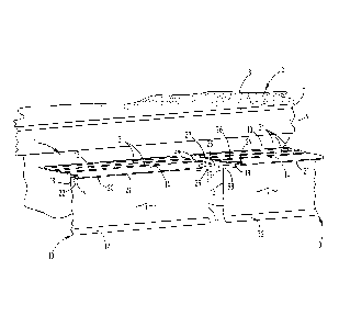
The reference numeral 1 (Figs. 1 and 2) generally designates a pre-notched
drip
edge assembly embodying the present invention. Pre-notched drip edge assembly
1 is
specifically designed for building roofs, such as the illustrated roof 2
having a plurality of
underlayment panels or sheathing 3 and a fascia 4 extending along the bottom
edge 5 of
roof 2.
Pre-notched drip edge assembly 1 includes a plurality of elongate drip edge
sections 10 having opposite ends 11 and 12 which are interconnected in an end-
to-end
relationship to form a continuous rainwater barrier along the bottom edge 5 of
roof 2.
Each of the drip edge sections 10 has a formed, one-piece construction, which
includes a
top flange portion 13 which is normally oriented generally horizontally, and
has a
forward edge area 14. Each pre-notched drip edge section 10 also includes a
front flange
portion 16 having an inverted, generally L-shaped configuration with a lower
leg 17
6
which is normally oriented generally vertically, and has an upper edge area
18. Front
flange portion 16 also has an upper leg 19 which is normally oriented
generally
horizontally, and has a forward edge area 20. The forward edge area 14 of the
top flange
portion 13 and the forward edge area 20 of the upper leg 19 are integrally
interconnected along a folded-over nose portion 21, which has a generally
wedge-
shaped side elevational configuration which projects outwardly from the lower
leg 17
and extends longitudinally along the drip edge section 10 to deflect rainwater
away from
the building. Each of the pre-notched drip edge sections 10 has a pair of
notches 24 and
25 formed in the opposite ends 11 and 12 of the drip edge section 10, which
extend a
preselected distance through the upper edge area 18 of the lower leg 17, the
forward
edge area 20 of the upper leg 19 and a forward edge area 14 of the top flange
portion
13, and define two generally flat end tab areas 26 and 27 on the top flange
portion,
which during installation, are inserted into the folded-over nose portion 21
of the next
adjacent ones of the drip edge sections 10 to horizontally and vertically
locate the same
for quick and accurate end-to-end interconnection of the drip edge sections 10
along the
building roof 2.
In the illustrated example, each drip edge section 10 of the pre-notched drip
edge assembly 1 has a substantially identical configuration, and is preferably
constructed from a strip of relatively thin sheet metal, such as aluminum or
steel, which
may have a baked-on paint surface or the like on the exterior side thereof.
Notches 24
and 25 similarly have a substantially identical shape, size and location on
the opposite
ends 11 and 12 of each drip edge section 10. As best illustrated in Figs. 6
and 6A, the
folded-over nose portion 21 of each of the drip edge sections 10 has a
slightly open,
tapered shape which defines a tapered slot area 22 that opens rearwardly, with
end
edges 28 and 29 that abut the end edges on the nose portions 21 of the next
adjacent
ones of the drip edge sections 10 to define a partially overlap, abutting
assembled
condition, as shown in Figs. 2 and 13-15A, and discussed in greater detail
below. The
slightly open, tapered shape of the folded-over nose portion 21 also
facilitates closely
receiving in slot area 22 the end of a next adjacent one of the drip edge
section in a
nested relationship which snap locks the ends together to define a fully
overlapped
assembly condition which is illustrated in Figs. 16-18A, and described in
greater detail
hereinafter.
7
CA 2768934 2018-11-05
In the illustrated example, the top flange portion 13 of each drip edge
section 10
has a plurality of raised, longitudinally extending reinforcing channels or
ribs 31 which
add rigidity to the structure. Also, the lower legs 17 of the illustrated drip
edge sections
have an angled, forwardly protruding bottom lip portion 32, which serves to
direct
5 rainwater away from the associated building. The illustrated notches 24
and 25 open
longitudinally, and are defined by end edges 28 and 29, lower edges 33 and 34,
and
upper edges 35 and 36.
With reference to Figs. 5, 14 and 15, in the illustrated example, the end tab
areas
26 and 27 of top flange portion 13 have a generally rectangular plan shape
(Fig. 5), and
10 are disposed at the opposite forward corners of top flange portion 13,
directly behind
the associated notches 24 and 25. The forward or leading edges of end tab
areas 26 and
27 are defined by notch edges 35 and 36, and extend along the entire length
thereof. In
one working embodiment of the present invention, end tab areas 26 and 27 have
a fore-
to-aft width in the range of 0.125-0.250 inches, and a longitudinal length in
the range of
.. 0.50 inches, so that when the same are received in the slot areas 22 of the
next adjacent
nose portion 21, they positively locate the two drip edge sections 10
vertically and
horizontally.
Figs. 7-12A illustrate a method embodying the present invention for making the
drip edge sections 10. With reference to Fig. 7, an elongate strip 40 of sheet
metal
material or the like, such as aluminum or steel, is unreeled from an
associated coil (not
shown), straightened, and fed into a stamping machine or the like which forms
a series
of rectangular windows 41 completely through the flat strip 40 at a location
slightly
offset from the center of the strip 40. In one working embodiment of the
present
invention, window 41 has a longitudinal length of approximately 1.00 inches,
and a
.. lateral width of approximately 0.54 inches. In the illustrated example,
after strip 40 is
completely formed to shape and cut into a plurality of individual segments,
each of the
subject drip edge sections 10 will have a length of approximately ten feet,
although it
will be understood that other lengths can also be formed, depending on the
specific
application. Consequently, the illustrated windows 41 are spaced approximately
ten feet
.. apart, as measured from the centerline of one window 41 to the centerline
of the next
adjacent window 41. After the windows 41 have been formed in the flat strip
40, the
windowed strip is then passed through a roll forming machine, or is otherwise
bent to
8
CA 2768934 2018-11-05
CA 02768934 2012-02-23
the formed shape illustrated in Figs. 7-12A. In the illustrated example, top
flange portion
13 is oriented at a predetermined included angle in the range of 85-90 degrees
from the
front flange portion 16, with top flange portion 13, and assumes a normally,
generally
horizontal orientation, and front flange portion 16 assumes a generally
vertical
orientation. After the windowed strip 40 has been roll formed into the formed
shape
illustrated in Fig. 8, the elongate windowed and formed strip is cutoff
lengthwise to
define a plurality of individual drip edge sections 10, which in one working
embodiment
of the present invention, are approximately ten feet in length. More
specifically, as best
illustrated in Figs. 11-12A, the windowed and formed strip 40 is positioned in
a fixtured
anvil, wherein the rearward portion of the top flange portion 13 rests a
buttingly on the
upper surface of an upper anvil member 48. The upper leg 19 of the front
flange portion
16 is abuttingly supported on the upper surface of a forward anvil member 49,
and the
lower leg 17 of front flange portion 16 extends through a slot 50 located
between upper
anvil member 48 and forward anvil member 49. In the illustrated example, a
vertically
reciprocating cutoff blade 51 is positioned above the anvil supported, or
fixtured
windowed and formed strip 40 at a location immediately above the centerline of
the
window 41. When the cutoff blade 51 is actuated, it passes through the top
flange
portion 13, the center of window 41 and then through the lower leg 17 of front
flange
portion 16, as illustrated by the broken cut line 52 in Fig. 11, thereby
forming an
individual drip edge section 10 with sidewardly or longitudinally opening
notches 24 and
at the opposite ends thereof. It is noteworthy that cutoff blade 51 passes
through the
formed windows 41 in strip 40, so that the folded-over nose portion 21 is not
flattened
or otherwise distorted from its original, formed designed shape, as shown in
Figs. 7-11,
during the cutoff operation. As noted above, in the manufacture of prior art
of the drip
25 edge sections, the cutoff operation completely closes off or flattens
the nose portion of
the drip edge, such that the top flange portion and the front flange portions
lay flat
against one another. In the present invention, the nose portion 21 remains
open with a
slightly open, wedge-shaped side elevational configuration which facilitates
easy
interconnection of adjacent drip edge sections 10 either in a partially
overlap, abutting
assembly condition, as shown in Fig. 2 and 13-15, or in a nested, snap locked,
fully
overlapped assembly condition, as shown in Fig. 16-18.
9
CA 02768934 2012-02-23
In operation, a plurality of drip edge sections 10 can be installed along the
,
= bottom edge 5 of an associated building roof 10 in a partially
overlapped, abutting
assembly condition, as shown in Figs. 2 and 13-15A, in the following fashion.
A first drip
edge section 10 is positioned over the outer edge of roof 2 and the fascia 4
in the
manner illustrated in Fig. 2, and attached to the roof 2 by fasteners that may
be driven
either through the front flange portion 16 into the fascia 4 and/or through
the top flange
portion 13 into the sheathing 3 of roof 2. If the roof 2 is pitched, the
installer bends the
top flange portion 13 of drip edge section 10 relative to the front flange
portion 16 along
nose portion 21 in a hinge like fashion to conform drip edge section 10 to the
exact
angle of roof 2. A second drip edge section 10 is placed in a longitudinally
aligned
relationship with the first installed drip edge section 10 and shifted
laterally in a
generally horizontal direction, so that the end tab'area 27 of the second drip
edge
section 10 is inserted into the slot area 50 of the nose portion 21 of the
first drip edge
section 10, which quickly and accurately locates the two drip edge sections 10
both
horizontally and vertically relative to one another in a longitudinally
aligned condition.
The end edges 28 and 29 of the adjacent nose portions 21 abut, thereby forming
a stop
which automatically indicates that the two drip edge sections 10 are in their
proper
position for installation on roof 2. In the example illustrated in Figs. 13-
15A, the top and
front flanges 13, 16 overlap each other approximately 0.50 inches. The second
drip edge
section 10 is then attached to the building roof 2 in a manner similar to that
of the first
drip edge section 10. Additional drip edge sections 10 are then installed in a
similar
manner until the edge of the roof 2 is completely covered. The notched ends of
the first
and last drip edge sections 10 may be cut off to form squared off ends.
Alternatively, a plurality of drip edge sections 10 can be installed along the
bottom edge 5 of an associated building roof 2 with a more conventional,
nested snap-
lock in a fully overlapped assembly condition, as shown in Figs. 16-18, in the
following
fashion. A first drip edge section 10 is attached to the building roof 2 in a
manner similar
to that described above, except that the interior end of the drip edge section
10 is left
unattached. A second drip edge section 10 is positioned in a fully overlapped
condition
along the rear surfaces of the first drip edge section 10 with the exterior of
the nose
portion 21 of the second drip edge section 10 disposed immediately behind the
interior
of the nose portion 21 of the first drip edge section 10. The adjacent ends
11, 12 of two
CA 02768934 2012-02-23
drip edge sections 10 are then converged into a nested relationship, so that
they snap
lock together in a fully overlapped assembly condition. Because the nose
portion 21 of
the drip edge sections 10 is slightly open with a tapered shape, it is easy to
snap the two
drip edge sections 10 together in a fully overlapped condition. In the example
shown in
Figs. 16-18, the top and front flanges 13, 16 overlap several inches, although
it is to be
understood that this amount can be readily changed by the installer, since
there is no
longitudinal stop feature with this assembly technique. The joined or
overlapped areas
of the drip edge sections 10 are then fastened to the roof 2. Additional drip
edge
sections 10 are then installed in a similar manner, until the bottom edge 5 of
the roof 2
is completely covered.
In the foregoing description, it will be readily appreciated by those skilled
in the
art that modifications may be made to the invention without departing from the
concepts disclosed herein. Such modifications are to be considered as included
in the
following claims, unless these claims by their language expressly state
otherwise.
11