Note: Descriptions are shown in the official language in which they were submitted.
CA 02769204 2014-05-22
REPEATABLE, COMPRESSION SET DOWNHOLE BYPASS VALVE
BACKGROUND
Technical Field
[0002] These
inventions relate, generally, to apparatus and methods used in well
servicing, such as oil and gas wells. More specifically, the inventions relate
to downhole
CA 02769204 2012-01-26
WO 2011/020006
PCT/US2010/045456
apparatus which when assembled in a tubing string can repeatedly and
selectively create a
fluid bypass in the circulating system of a well being serviced.
Background Art
[0003] As is known in the relevant art, bypass tools are typically run
into
wellbores assembled or connected in a tubular string and are utilized to
selectively discharge
fluids from the interior of the tubing string into the annular space around
the tool. In some
applications, this discharge is used to boost or assist the flow of debris in
the annulus.
[0004] As used herein, the words "comprise," "have," "include," and
all
grammatical variations thereof are each intended to have an open, non-limiting
meaning
that do not exclude additional elements or steps. The term "wellbore" refers
to the
subterranean well opening, including cased and uncased. The term "tubing
string" is
used generically to refer to tubular members positioned in a wellbore, such as
drill pipe,
tubing and the like. The term "well fluids" refers broadly to any fluids found
in a
wellbore. As used in this application, the term "bypass" refers to a fluid
flow path from the
bore or interior of a tubing string into the wellbore/tubing string annulus,
at some point along
the length of the tubing string, rather than out the lower most end of the
tubing string and
downhole assembly. It is understood that even in a bypass mode, some fluid may
still
traverse the length of the tubing string and exit the lowermost end thereof As
used herein,
"weight down" is used to describe a condition of the tubing string where at
least a portion of
the weight of the tubing string is supported downhole in compression rather
than tension. As
used herein, the term "poppet valve" is used to refer to a valve operated by
springs or the like
that plugs and unplugs its openings by axial movement.
SUMMARY OF THE INVENTIONS
[0005] The present inventions provide a tool with a tubular body for assembly
in a tubing string which can be selectively activated to provide bypass flow.
The tool
preferably includes a body with one or more ports or passageways connecting
the interior
of the tubing string with the annulus. The tool includes metallic, ball-shaped
valves and
metallic seats. The ball-shaped valves can be cycled or moved into and out of
positions
2
CA 02769204 2012-01-26
WO 2011/020006
PCT/US2010/045456
blocking or permitting bypass flow through the passageways even when the fluid
are
being pumped through the tool under pressure. In other words, it is not
required to shut
down fluid circulation when activating the tool. In addition, the tubing
string can be
rotated and axially cycled while the tool is in the bypass flow position.
BRIEF DESCRIPTION OF THE DRAWINGS
[0006] The drawings are incorporated into and form a part of the
specification
to illustrate at least one embodiment and example of the present inventions.
Together
with the written description, the drawings serve to explain the principles of
the
inventions. The drawings are only for the purpose of illustrating at least one
preferred
example of at least one embodiment of the inventions and are not to be
construed as
limiting the inventions to only the illustrated and described example or
examples. The
various advantages and features of the various embodiments of the present
inventions
will be apparent from a consideration of the drawings in which:
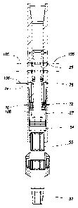
[0007] Figure 1 is a partial section view of the bypass valve of the
present
inventions illustrated in a closed position;
[0008] Figure 2 is a partial section view of the bypass valve of the
present
inventions in a weight down position (that is, where weight has been set down
on the tool,
thereby putting the tool in longitudinal compression and shifting the inner
mandrel with
respect to the main body);
[0009] Figure 3 is a partial section view of the bypass valve of the
present
inventions in an open or bypass position;
[0010] Figure 4 is an enlarged perspective view of the spool element
of the
bypass valve of the present inventions; and
[0011] Figure 5 is an enlarged sectional view of the check valve
portion of the
tool of the present inventions.
3
CA 02769204 2012-01-26
WO 2011/020006
PCT/US2010/045456
DETAILED DESCRIPTION OF THE INVENTIONS
[0012] Referring now to the drawings, wherein like reference characters
refer
to like or corresponding parts throughout the several figures, there is
illustrated in Figure
1, compression set bypass valve 10 positioned in a wellbore 12, forming an
annulus 14
around the tool inside the wellbore. Typically, the wellbore 12 contains well
fluids, such
as drilling mud, debris such as cuttings and the like and can be cased (as
illustrated) or
uncased. In Figure 1, the arrow "H" references the uphole or well head
direction, without
regard to the actual physical orientation of the wellbore. The bypass valve 10
has an
elongated tubular shape comprising a main body 20 with means thereon,
typically threaded
connections 30 and 57, for connecting the tool in a tubing string 16. In the
illustrated
embodiment, the bypass valve 10 is connected in a tubing string. In this
embodiment, the
tubing string 16 is a drill string and the bypass valve 10 is connected in the
tubing string
between the well head and the drill bit or clean out tool (not shown).
100131 A central passageway or bore 22 extends the length of the bypass
valve
10, as shown, and when assembled in a tubing string the passageway is in fluid
communication with the interior of the string as indicated by arrows F. Main
body 20
may be made in two body sections 20A and 20B, joined by a threaded connection
24. Two
axially spaced sets of ports 26 extend through the wall of the upper body
section 20A. In
this embodiment, each set comprises a plurality of ports, in this example,
four ports are
circumferentially spaced at 90 degree intervals. Also, in this embodiment only
two sets of
ports are illustrated, however it should be understood that, depending on the
valve diameter
and bypass flow requirements, more or less sets could be present. As will be
described,
these ports 26, when open, provide bypass flow from the bore 22 of the bypass
valve 10 to
the annulus 14.
[0014] A generally cylindrical spool 40 is disposed within bore 22 of
main
body 20 for rotational and axial movement therein. The term "spool" is not
intended to be
limited to a particular shape. The spool 40 is located adjacent the ports 26.
Figure 4
illustrates additional details of spool 40. Spool 40 comprises a continuous
indexer slot 42
formed in the outer wall of the spool. In this embodiment, the indexer slot 42
contains eight
4
CA 02769204 2012-01-26
WO 2011/020006
PCT/US2010/045456
notch configurations 43 spaced 45 degrees apart. The function of indexer slot
42 is described
in more detail later.
10015] Spool
40 is held within bore 22 by one or more index pins 25 mounted to
extend through the wall of main body 20 so as to protrude into indexer slot
42. It is
understood that spool 40 may move axially and rotate as the index pins 25 ride
or are
confined in the indexer slot 42. It is to be understood that the positions of
the pin and slot
could be reversed, with the slot formed on the interior of the body and the
pin mounted on the
body. Spool 40 further comprises a plurality of openings or ports 44 through
the wall of the
spool 40. As shown, the spool of the illustrated embodiment has two axially
spaced sets of
eight ports 44. These ports 44 are circumferentially spaced 45 degrees apart.
The axial
spacing of these sets of ports 44 correspond to the axial spacing of the sets
of ports 26 in
the upper section 26a. Balls 46, preferably of hard metal such as carbon
chrome, are
mounted in enlarged (counter-bored) alternate ports 44. When fluid pressure or
flow is present
inside the spool 40, the balls 46 move outwardly so as to seal the flow path
through ports 44
and 26These counterbores form pockets for loosely retaining the balls. Ports
44 are spaced
and mounted to align with ports 26 in upper body section 20a. When spool 40 is
in one
position (with the index pins 25 resting in one notch configuration 43), balls
46 are aligned
with ports 26, and when so aligned, balls 46 are moved outwardly by fluid
pressure/flow so as
to seal the ports 26 and prevent any fluid flow through ports 44 and 26. When
spool 40 is in the
adjacent position (with the pins 25 located in the adjacent notch
configuration 43), namely
rotated one "notch," then open ports 44 (that is, without balls 46 therein)
are aligned with ports
26, and the bypass is thereby open and fluid may flow from bore 22 into the
annulus 14,
thereby affecting the bypass. The method of moving the spool 40 from between
the notch
configurations 43 will be described hereinafter. It is understood that the
alternate ports 44
and balls 46 could be eliminated, allowing the spool to act as a valve
element.
[0016] The
bypass valve 10 also comprises a mandrel 50 disposed within main
body 20. As illustrated in the drawings, mandrel 50 comprises a longitudinal
bore 52. A
reduced or smaller diameter upper mandrel section 53 extends upwardly into
bore 22 of main
body 20 and is connected to the spool 40 at 49. A lower, larger diameter
plunger section 54
is sized to fit snugly within a chamber 27 formed within the lower body
section 20B of the
CA 02769204 2012-01-26
WO 2011/020006
PCT/US2010/045456
main body 20. Preferably, external splines 55 engage internal splines 29
formed in chamber
27 of the lower body section 20A. The interaction or meshing of the splines
serves to
rotationally lock mandrel 50 in the main body 20 while permitting and
telescoping movement.
Plunger section 54 further comprises seals 56 to provide a fluid seal with the
walls of
chamber 27. The lower end of mandrel 50 preferably has a means for connecting
the
mandrel to a drill string, such as threaded connection 57. Mandrel 50 may also
be provided
with a second set of external splines 58, which serve as a mounting base for
an enlarged
diameter member such as a stabilizer or landing ring 100.
[0017] Bypass valve 10 further comprises a check valve system which
controls
fluid flow into and out of the chamber 27. As will be explained, the check
valve system
operates as a mechanical trigger which can be preset to prevent telescoping of
the mandrel
with the body unless a set telescoping force is applied. Figure 5 shows
greater detail of the
check valve system. The check valve system comprises a plurality of one way or
check
valves, such as poppet valves 70 and 72 controlling the flow respectively
through with fluid
passage 74 and 76. One of the valves, for example poppet valve 70, controls
fluid flow
through fluid passage 74 and into chamber 27 (but does not permit flow out of
the chamber).
The poppet valve 72 control fluid flow through fluid passages 76 and out of
chamber 27 (but
does not permit flow into the chamber). While only two poppet valves 70 and 72
are shown
for simplicity, it is to be understood that bypass valve 10 may comprise a
greater number of
poppet valves, such as two valves controlling fluid flow into chamber 27 and
two valves
controlling fluid flow out of chamber 27.
[0018] In the illustrated embodiment, the poppet valves 70 and 72
comprise balls
77 and 78, respectively, which act as valve elements. So as to affect the
fluid seal, springs 79
resiliently urge the balls 77 and 78 against seats 80 and 82, respectively.
Springs or other
biasing elements can be selected, as desired, to control the pressure required
to open the
valves for fluid entry/exit. The springs are selected to apply sufficient
force to the balls to
prevent friction or drag on the tubing String and landing ring 100 during
insertion in the well
from causing poppet valve 72 to opening. On the other hand, the springs are
selected so that
poppet valve 72 will open and discharge fluid from chamber 27 when the string
is in the
weight down condition.
6
CA 02769204 2012-01-26
WO 2011/020006
PCT/US2010/045456
[0019] For example, with bypass valve 10 in the closed position (Figure
1), the
tubing string can be placed in a weight down condition with the landing ring
100 supported
from a liner top 102 (illustrated in Figure 2). In this weight down condition,
a down hole
directed force is applied to bypass valve 10 (and chamber 27B) while the
mandrel 50 is held
in position. This force causes plunger 54 to compress the fluids in chamber
27. When a
sufficient force is reached to cause the pressure in chamber 27 to overcome
the springs 79
holding balls 78 against its seat 82, fluid will be discharged from the
chamber through fluid
passage 76. This in turn will allow bypass valve 10 to move down (telescope)
with respect to
the plunger 54 and the weight of the tubing string will force upper mandrel
section 53 to lift
spool 40. As the spool 40 moves axially up (direction of arrow H), index pins
25 will move
to the bottom of the notch configuration 43, rotating the spool 22 'A degrees.
When the string
is lifted off the liner top 102, lower body section 20B will be lifted and the
weight of the
tubing string will force plunger 54 to pump fluid into chamber 27 through
passageway 74
and past poppet valve 70. As the lower body section 20B is lifted, the pins 25
will move to
the top of the adjacent notch configuration 53, which in turn rotates the
spool an additional 22
1/2 degrees, for a total of 45 degrees, which opens the bypass valve 10 to the
bypass condition
(Figure 3). The procedure can be repeated to close the bypass valve 10.
[0020] Other structural features of bypass valve 10 and how the various
parts
interact with one another can be described by a description of the operation
or function of
bypass valve 10 by reference to Figures 1 - 3. In Figure 1, the bypass valve
10 is illustrated
in a closed position, that is, no fluid path or bypass exists from the bore 22
of the valve to the
annulus 14. While the tool may be run into a wellbore in either a closed or
open position, a
process will be described wherein the tool is run into the wellbore in a
closed position (as in
Figure 1).
[0021] Prior to the tool being run into the wellbore, spool 40 is
rotated such that
balls 46 are aligned with ports 26 in main body 20. In this position, fluid
flow through the
ports is blocked, and the tool is therefore "closed." As illustrated, mandrel
50 is in a
lowermost position with respect to main body 20. In this position plunger
section 54 is at the
bottom of chamber 27. As bypass valve 10 is lowered into the wellbore,
wellbore fluid is in
chamber 27. It is understood that poppet valve 70 can be spring biased to open
at a desired
7
CA 02769204 2012-01-26
WO 2011/020006
PCT/US2010/045456
pressure to equalize the pressure in chamber 27 and the annulus 14. Fluid in
chamber 27
cannot flow from chamber 27 until the telescoping force on the valve and
pressure in
chamber 27 overcomes the opening pressure/force for poppet valve 72 (which is
spring
biased to open at a desired pressure). As the string containing the tool is
inserted into the
well, drag forces on the tool string below the bypass valve 10 may cause the
plunger 54 to
compress the well fluid in chamber 27; however, by selecting a spring 79 with
sufficient bias
on the ball 72 to prevent fluid discharge, inadvertent activation of the tool
can be avoided. It
is understood that mandrel 50 can move longitudinally with respect to main
body 20, within
structural limits, but mandrel 50 and main body 20 are always rotationally
locked by virtue of
splines 55 and 28. This feature permits rotating the drill string below bypass
valve 10 in
either closed or bypass position.
[0022] in
order to open the bypass valve 10 when down hole, it is necessary to
move main body 20 with respect to the mandrel 50, which in turn causes the
spool 40 to
rotate with respect to upper body section 20A. This movement is created by
placing the
bypass valve 10 in a weight down position as illustrated in Figure 2. In
Figure 2, the tubing
string has been lowered until landing ring 100 contacts the liner hanger 102.
In this position,
downward movement of the mandrel 50 is prevented by contact between the ring
100 and
hanger 102. Continued lowering of the tubing string places substantial weight
down on the
tool, causing the upper body 20A to move downward (telescope) with respect to
the mandrel
50 which if the weight is sufficient causes plunger 54 to pump the fluid from
chamber 47
through poppet valve 72 and out passages 76 as indicated by arrow 104.
Downward
movement of the upper body section 20A also causes spool 40 to rotate, by
virtue of an
angled portions (or drum cam surfaces) of indexer slot 42 bearing against
indexer pins 25.
When the upper body 20A is thereafter lifted or moved upward, the action of
the indexer pins
25 and slot 42 completes rotation of the spool 40 to the open position. This
combined
longitudinal/rotational or "indexing" rotates the open ports in spool 40 into
alignment with
ports 26 in main body 20.
[0023] It can
be appreciated that telescoping movement between the mandrel 50
and the main body 20 causes plunger section 54 to pump the fluid in chamber 27
out of
chamber 27 through poppet valve 72. As previously mentioned, poppet valve 72
can be
8
CA 02769204 2012-01-26
WO 2011/020006
PCT/US2010/045456
preset so as to control the amount of force which must be imposed on mandrel
50 to cause fluid
to flow through poppet valve 72. This aspect of bypass valve 10 permits the
user to control
how much weight must be set down before poppet valve 72 will permit fluid to
flow from
chamber 27, and thereby permit mandrel 50 to move into main body 20. As
previously
pointed out, setting the poppet valve 72 to a sufficient level prevents
inadvertent activation of
the valve during insertion and axial movement in the well.
[0024] As mentioned above, after mandrel 50 has been moved upwardly,
by
setting weight down on bypass valve 10, the drill string must be raised so as
to move the
main body 20 upward with respect to the mandrel 50, thereby moving spool 40
downwardly
so as to align open ports 44 (namely, without balls 46 therein) and 26, and
forming the fluid
bypass flow path. As can be seen in Figure 3, the bypass valve 10 has been
raised until
the mandrel 50 is again at its lowest position. As the bypass valve 10 is
raised, well fluids
flow into chamber 27 through fluid passages 74 and poppet valve 70 as
indicated by arrows
106. Now, spool 40 is also moved into its lowest position, and the flow ports
are aligned for
bypass flow as indicated by arrows 105.
100251 The bypass valve can be cycled between open and closed
positions as
many times as desired, by setting weight down on the tool and then picking up.
This
endless cycling of the valve is accomplished by making the indexer seat 42
endless. In this
embodiment, the indexer slot extends continuously circumferentially around the
spool 40. It
is envisioned that configurations of continuous indexer slots are known in the
industry and
would enable endless cycling of the valve. Balls 46 in spool 40 are preferably
made of
carbon chrome steel, and thereby form a metal-to-metal seal in ports 26,
enabling the tool
cycling to be done under flow conditions, e.g. while fluid bypass is
occurring, without cutting
out of the hard metal balls or seats. This is in distinction to prior art
bypass valves which
used resilient seal elements, such as 0-rings, which are highly likely to be
cut and destroyed by
fluid flow thereby. Replaceable, removable annular seats (see Figures 1-3)
conform to the
spherical valve element, and the ball's movement to the seat accommodates wear
and
assembly tolerances. As described, the ball is loosely held in the counterbore
formed pocket
arid differential pressure moves the ball up against the seat to seal, like a
ball check valve.
9
CA 02769204 2012-01-26
WO 2011/020006
PCT/US2010/045456
This loose mounting of the ball accommodates sealing even with misalignment
and part
wear.
[0026] Several novel aspects flow from the structure and operation of
the tool.
Once the tool has been placed into either the bypass open or closed positions,
reciprocation of the drill string and tool can be resumed; this is in contrast
to known prior
art downhole bypass valves which (once the bypass has been opened) require
that the tool be
kept in compression to maintain the bypass open, thereby preventing
reciprocation of the
drill string. As described above in the operational sequence, the bypass can
be cycled an
unlimited number of times, yielding a repeatable bypass activation system.
This
repeatable aspect is of key importance should the bypass mechanism be
prematurely
opened, for example from encountering a downhole obstruction while tripping in
the
hole, shifting the tool because of high down hole fluid friction forces, etc.
The
present inventions are capable of handling high pressures, as the metal-to-
metal
seal in the bypass is not readily deformed or destroyed by high pressures.
Finally,
the structure of the tool lends it to use with any type of fluid in the
wellbore, from
solids laden mud to clear brines.
[0027] As is well known in the relevant art, high strength metals and
metal
alloys may be used to fabricate many of the parts of the bypass valve. Seal
elements
(such as 0-rings or other resilient seals) are provided as necessary to create
fluid/pressure seals between components.
100281 While the preceding description contains many specificities, it
is to
be understood that same are presented only to describe some of the presently
preferred embodiments of the inventions, and not by way of limitation. Changes
can
be made to various aspects of the inventions, without departing from the scope
thereof. For example, dimensions and materials can be changed to suit
particular
situations; the tool can be run in conjunction with other downhole tools; etc.
Therefore,
the scope of the inventions is not to be limited to the illustrative examples
set forth
above, but encompasses modifications which may become apparent to those of
ordinary skill in the relevant art.
CA 02769204 2014-05-22
[00291 Therefore, the present inventions are well adapted to cany out
the objects
and attain the ends and advantages mentioned as well as those which are
inherent therein.
While the inventions have been depicted, described, and are defined by
reference to
exemplary embodiments of the inventions, such a reference does not imply a
limitation on the
inventions, and no such limitation is to be inferred. The inventions are
capable of
considerable modification, alteration, and equivalents in form and function,
as will occur to
those ordinarily skilled in the pertinent arts and having the benefit of this
disclosure. The
depicted and described embodiments of the inventions are exemplary only, and
are not
exhaustive of the scope of the inventions. Consequently, the inventions are
intended to be
limited only by the scope of the appended claims, giving full cognizance to
equivalents in all
respects.
[0030] Also, the terms in the claims have their plain, ordinary meaning
unless
otherwise explicitly and clearly defined by the patentee. Moreover, the
indefinite articles "a"
or "an", as used in the claims, are defined herein to mean one or more than
one of the element
that it introduces. If there is any conflict in the usages of a word or term
in this specification
and one or more patent(s) or other documents that may be incorporated herein
by reference,
the definitions that are consistent with this specification should be adopted.
11