Note: Descriptions are shown in the official language in which they were submitted.
CA 02769431 2012-02-29
TITLE
Segmented Brake Rotor with Externally Vented Carrier
CROSS-REFERENCE TO RELATED APPLICATIONS
[0001] This application claims the benefit of United States Provisional Patent
Application No.
61/464,280, filed on March 1, 2011, as well as United States Provisional
Patent Application No.
61/629,751, filed on November 25, 2011, both in the names of Geoffery K.
McCord et al., and
entitled "Segmented Brake Rotor with Externally Vented Carrier". The entire
contents of these
earlier filed and commonly owned patent applications is herein expressly
incorporated by
reference.
STATEMENT REGARDING U.S. FEDERALLY SPONSORED RESEARCH
[00021 None.
BACKGROUND OF THE INVENTION
1. Field of the Invention
[0003] The present invention relates to braking systems for vehicles,
including aircraft, and
more particularly pertains to the brake rotors and segmented brake rotors in a
disc braking
system.
2. Discussion of Related Art
[0004] Increasing fuel prices, fuel economy and emission standards provide
incentive to reduce
the mass of vehicles by substituting light weight components in place of heavy
steel or cast iron
components. A large opportunity for such mass reduction exists in the
vehicles' braking system.
[0005] A disc-and-caliper braking system is increasingly common on motor
vehicles, and in
particular, becoming more common on military, commercial and vocational
vehicles. In this
system, braking is effected by high pressure hydraulic fluid forcing one or
more pistons in a
caliper to press a pair of brake pads against the friction surface of a brake
rotor. The brake rotor
CA 02769431 2012-02-29
is connected to, and rotates at the same speed as the wheel of the vehicle.
The brake rotor
traditionally is made from a ferrous-based material such as cast iron or
steel. These materials
have worked well for many years, but suffer from relatively high weight.
[00061 In recent times, brake designers have experimented with brake rotors
based on aluminum
and its alloys. Aluminum is much lighter than iron or steel, but cannot
operate at as high a
temperature as iron steel, a significant drawback in a braking system where
operating
temperatures can exceed 600C. Aluminum also has a much higher coefficient of
thermal
expansion (CTE) than does iron or steel. An aluminum brake rotor that is
constrained as it heats
up under braking action is at risk of warping or buckling. Aluminum also has a
much higher
thermal conductivity than does iron or steel. As such, if the heat of braking
is not dissipated into
the surrounding air, it will more quickly travel into the surrounding
structure to which it is
mounted, which could have an adverse effect on other component material and
lubricants.
[00071 Accordingly, many brake rotor designs rely on vents to help dissipate
heat into the
surrounding air. Incorporating vents into the brake rotor design adds
complexity and therefore
cost. To present a uniform friction surface, the vent designs typically are
internal to the brake
rotor. Brake rotors typically are made by a casting process. Unless the rotor
is cast in two half-
disc units and later assembled, the internal vents cause difficulty in
casting, what with metal
having to be cast around sand or similar cores, and the cores subsequently
being removed to
create the vents.
[00081 U.S. Patent No. 6,536,564 addresses the problem of casting in the vents
in a vented brake
rotor design, more specifically an aluminum composite or Metal Matrix
Composite(MMC)
brake rotor design. Specifically, and in one particular embodiment, a vented
disc brake rotor
features first and second braking surfaces that jointly define inner and outer
circumferential
surfaces and a central region. A hub surface is disposed in the central region
and contains a main
aperture adapted for mounting the rotor onto a vehicle. A plurality of curved
directing walls are
disposed between the first and second braking surfaces to define a plurality
of flow channels.
Each flow channel extends from the inner circumferential surface to the outer
circumferential
surface. A curved separating wall is disposed in each flow channel and extends
from a point
between the inner and outer circumferential surfaces to the outer
circumferential surface. The
2
CA 02769431 2012-02-29
separating wall can divide the flow channel into two subchannels. Also, the
separating wall has a
width that increases from its first end to its second end located at the outer
circumferential
surface. As a result, each flow channel has a total cross-sectional area that
remains substantially
constant from the inner circumferential surface to the outer circumferential
surface. Lastly, a
plurality of directing fins is disposed on the inner circumferential surface.
Each directing fin
defines a directing surface and is adapted to direct air into a flow channel
positioned adjacent the
directing fin. Each flow channel may be opened to one of the braking surfaces,
giving a gapped
or intermittent configuration to the braking surface(s). This configuration
may facilitate
manufacturing by allowing the first and second braking surfaces to be
integrally formed by a
singular brake member by a suitable process, such as die-casting or squeeze-
casting.
[00091 Another problem with a light metal such as aluminum is that it is
softer than iron or steel,
and thus wears out faster in frictional contact with a brake pad. Accordingly,
some brake
designers have modified the frictional surface of an aluminum brake rotor to
address the wear
problem and to maintain or perhaps even enhance the frictional characteristics
of the surface. A
popular approach to this modification is to add or incorporate wear plates to
the brake rotor
frictional surface. In its simplest form, the wear plates take the form of an
annular ring attached
to each of the two frictional surfaces in a typical brake rotor. The
attachment may be by means
of common fasteners such as bolts or rivets. In another embodiment, the
frictional surfaces of
the brake rotor are machined somewhat to accommodate the thickness of the
annular rings
without changing the overall profile or thickness of the original brake rotor.
[00101 One common issue with this approach is that there is often a large
difference in the CTE
between the wear plates and the aluminum substrate, chassis or "carrier". As
the system heats
up, the wear plates and carrier attempt to expand at different rates. Since
they are constrained, at
least to some degree, there is the potential to warping or buckling of the
carrier, or fracture of the
wear plates.
[00111 One modification that at least partially addresses this problem is to
break up the annular
wear plate ring into a plurality of wear or friction plate segments. In
addition to the known
fasteners, wear or friction plate segments can be attached to the brake rotor
carrier and held in
position by machining recesses in the friction surfaces, and placing the wear
or friction plate
3
CA 02769431 2012-02-29
segments into the recesses. U.S. Patent No. 6,935,470 is but one example among
many of this
approach.
[00121 Despite these developments, there are still problems with applying wear
plates,
segmented or annular, to the friction surfaces of a brake rotor carrier
fashioned from a
lightweight metal such as aluminum. In particular, a common deficiency exists
in segmented
rotors in the absorption and dissipation of the heat created on the braking
friction surfaces. Heat
management, even in internally vented rotor carriers, remains a significant
performance issue as
the rotor cannot dissipate the heat generated during the braking action
quickly.
The instant invention addresses and solves this problem.
SUMMARY OF THE INVENTION
[00131 In accordance with the instant invention, the externally vented brake
rotor (EVR) core
design, such as exemplified by U.S. Patent No. 6,536,564, is being used to
improve the function
and effectiveness of a segmented brake rotor (SBR) through more efficient
management of the
thermal forces created in the segmented rotor. In particular, an EVR is
resized as required in the
friction surface area to accept two or more segmented wear plates that are
fastened to the resized
rotor "carrier" platform. The friction wear plates can be any available
suitable braking material
such as cast iron, stainless steel, MMC alloys, titanium, carbon ceramic and
so on, which are
fastened to the rotor carrier using commonly known mounting fasteners such as
rivets. The
novel design of the EVR, when applied to the segmented rotor carrier platform,
results in
improved convection, radiation and conductive heat dissipation, and increased
transfer of heat
from the friction plates to the lightweight rotor carrier platform for
dissipation.
BRIEF DESCRIPTION OF THE FIGURES
100141 FIG. 1 is a peripheral view of a prior art brake rotor.
4
CA 02769431 2012-02-29
[00151 FIG. 2 is a peripheral view of a brake rotor carrier according to a
first embodiment of the
present invention.
[00161 FIG. 3 is a radial sectional view of a rotor similar to the rotor
illustrated in FIG. 2.
[00171 FIG. 4 is a magnified view of the brake rotor illustrated in FIG. 3.
[00181 FIG. 5 is peripheral view of a brake rotor carrier according to a
second embodiment of
the invention.
[00191 FIG. 6A is a side and top view of a single friction plate segment.
[00201 FIG. 6B is an isometric view of a friction plate segment featuring a
pair of tabs or
protrusions designed to engage corresponding recesses in a carrier surface.
[00211 FIG. 7 is an exploded isometric view of the major components of a
vented brake rotor
embodiment of the instant invention.
[00221 FIG. 8 is an isometric view of an assembled vented brake rotor
embodiment of the instant
invention.
DETAILED DESCRIPTION OF THE INVENTION
[00231 The invention is an extension of U.S. Patent No. 6,536,564 for an
externally vented brake
rotor (EVR). The EVR core design is being used to improve the function and
effectiveness of a
segmented brake rotor (SBR) through more efficient management of the thermal
forces created
in the segmented rotor. A common deficiency exists in segmented rotors in the
absorption and
dissipation of the heat created on the braking friction surfaces. The novel
design on the EVR,
when applied to the segmented rotor carrier platform, results in improved
convection, radiation
and conductive heat dissipation, greater surface area, increased volume and
velocity of air flow
CA 02769431 2012-02-29
through and around the rotor friction area and increased transfer of heat from
the friction plates
to the lightweight rotor carrier platform for dissipation.
[00241 The invention contemplates an alloy, alloy composite or ultra light
composite(common
aluminum compounds, MMC, high strength aluminum polymer, carbon fiber, etc.)
based EVR,
resized as required in the friction surface area to accept two or more
segmented wear plates that
are fastened to the resized rotor "carrier" platform. The friction wear plates
can be any available
suitable braking material such as cast iron, stainless steel, MMC alloys,
titanium, carbon ceramic
and so on, which are fastened to the rotor carrier using commonly known
mounting fasteners
such as rivets. Different materials can be used as the friction plates at the
same time, either on
one or the other friction surface, or alternating on the same surface.
The Internally Vented Brake Rotor (not part of the instant invention)
[00251 Before the concept of the "Externally Vented Brake Rotor" can be
discussed, some
terminology must first be discussed and explained in the context of the
Internally Vented Rotor
(NR). The IVR is not part of the instant invention.
[00261 FIG. 1 illustrates an internally vented disc brake rotor 10. The rotor
10 comprises a brake
member 12 having first 14 and second 16 braking surfaces. Also, the rotor 10
has an inner
circumferential surface 18 and an outer circumferential surface 20. The
braking surfaces 14, 16
are annular and therefore define a central region 22. A hat region 24 is
disposed in the central
region 22, and defines mounting surface 25 and a hub pilot 26. In use, the
rotor 10 is mounted to
a shaft end, such as an axle, by passing the shaft end through the hub pilot
26 and securing the
mounting surface 25 to a mounting portion of the shaft, such as conventional
wheel studs.
The Externally Vented Brake Rotor (a part of the instant invention)
[00271 FIG. 2 illustrates a first embodiment of a brake rotor that can be used
in connection with
the instant invention.
6
CA 02769431 2012-02-29
[0028] In this embodiment, the rotor 110 includes a singular brake surface
member 112 that
defines the first 114 and second 116 braking surfaces. Also, a first plurality
of directing walls
128a extends from an underside 115 of the first braking surface 114 toward the
second braking
surface 116, and a second plurality of directing walls 128b extends from an
underside 117 of the
second braking surface 116 toward the first braking surface 114.
[0029] Also preferable, the first braking surface 114 defines a first
plurality of gaps 170a that
provide access to at least one of a first set of flow channels 130a. Likewise,
the second braking
surface 116 defines a second set of gaps 170b providing access to at least one
of a second set of
flow channels 130b. Preferably, each flow channel of the first set of flow
channels 130a is
disposed between two flow channels of the second set of flow channels 130b. In
this
arrangement, the rotor 110 includes flow channels 130 oriented towards
opposing braking
surface 112, 114 in an alternating fashion.
[0030] Also, the gaps 170a providing access to the first set of flow channels
130a extend into
the inner circumferential surface 118. Since the hat region 124 is disposed
between the second
set of flow channels 130b and the inner circumferential surface 118, an
aperture 172 in the inner
circumferential surface 118 provides fluid access to the second set of flow
channels 130b.
[0031] A separating wall 132 is preferably disposed within each flow channel
130. Each
separating wall 132 is a solid wall member having first 134 and second 136
ends. The first end
134 is preferably disposed at a point between the inner circumferential
surface 118 and the outer
circumferential surface 120. Particularly preferable, the first end 134 is
disposed at a point
nearer the outer 120 circumferential surface than the inner circumferential
surface 118. The
second end 136 preferably comprises a portion of the outer circumferential
surface 120. Similar
to the directing walls 128, the separating walls 132 can be straight or
curvilinear in form.
Preferably, the separating walls 132 are similar in form to the directing
walls 128. Accordingly,
the separating walls 132 preferably have a curved configuration. Each side of
the separating wall
132 preferably conforms substantially to the curvilinear shape of the adjacent
directing wall 128.
[0032] Similar to the directing walls 128, the separating walls 132 preferably
extend from an
underside of the first braking surface 114 to an underside of the second
braking surface 116. As
7
CA 02769431 2012-02-29
a result, each separating wall 132 can maintain a unitary channel design or
divided the
appropriate flow channel 130 into first 138 and second 140 subchannels. The
channel or
subchannels 138, 140 terminate in openings 139 on the outer circumferential
surface 20. Thus,
as best illustrated in FIG. 2, the flow channels 130 begin as a single
passageway at the inner
circumferential surface 118 and terminate at the outer circumferential surface
120 as either a
single passageway 230 (best seen in FIG. 5) or two independent passageways
Fig. 2 138, 140 as
may be required by the application.
[00331 FIG. 3 is a longitudinal cross-section of a brake rotor design similar
but not necessarily
identical to that illustrated in FIG. 2. As best illustrated in FIG. 3, a
plurality of directing walls
28 are disposed between the first 14 and second 16 braking surfaces. The
directing walls 28 can
be straight or curvilinear in form. As illustrated in FIG. 3, the directing
walls 28 preferably
extend from the inner circumferential surface 18 to the outer circumferential
surface 20 along a
curvilinear path. Also preferable, the directing walls 28 extend from an
underside of the first
braking surface 14 to an underside of the second braking surface 16.
100341 As a result of this configuration, each adjacent pair of directing
walls 28 define a flow
channel 30 that extends from the inner circumferential surface 18 to the outer
circumferential
surface 20. The flow channel 30 is open at both ends, thereby allowing fluid
communication
between the central region 22 and outer 20 circumferential surfaces. Also, in
the embodiment
illustrated in FIG. 3, the flow channels 30 have a curved configuration due to
the curvilinear
shape of the directing walls 28.
100351 Referring again to FIG. 2, the total cross-sectional area of each flow
channel 130
preferably remains substantially constant over the length of the flow channel
130 from the inner
circumferential surface 118 to the outer circumferential surface 120. That is,
the cross-sectional
area of the flow channel 130 at a point near the inner circumferential surface
118, i.e., a point on
the flow channel 130 in which the flow channel comprises a single passageway,
is preferably
substantially identical to the sum of the cross-sectional areas of the first
138 and second 140
subchannels at a point near the outer circumferential surface 120
8
CA 02769431 2012-02-29
[0036] A plurality of directing fins 144 project into the central region 122.
Preferably, the fins
144 are defined by the brake member 112. The fins can be, however, separately
attached
members. Each directing fin 144 is disposed adjacent a flow channel 130. Also,
each directing
fin 144 defines a directing surface 146 that directs air into the flow channel
130. Preferably, as
best illustrated in FIG. 2, the directing surface 146 comprises a curved or
angulated surface. This
allows the directing fin 144 to alter the course of air encountering the
directing surface 146 and
direct it into the flow channel 130.
[0037] FIG. 3 shows a side view in cross section of similar directing fins.
FIG. 4 is a higher
magnification view of FIG. 3. Here, the directing fins are identified as 44,
the directing wall is
46, and the flow channel is 30.
[0038] FIG. 5 illustrates a brake rotor according to a second embodiment that
can be used in
connection with the present invention. This embodiment is similar to the first
embodiment
except as detailed below. Accordingly, like references numbers refer to
similar features and/or
components illustrated in FIG. 2.
[0039] In this embodiment, flow channels 230 have a constant width along their
length from the
inner circumferential surface 218 to the outer circumferential surface 220.
The desired
substantially constant cross-sectional area is accomplished in this embodiment
by elimination of
the separating wall 132 in FIG. 2. Accordingly, flow channels 230 are unitary,
lacking the first
and second subchannels of the previous embodiments.
[0040] The brake rotor carriers of the present invention can be fabricated by
any suitable
manufacturing process. However, the brake rotors of the first and second
embodiments of the
present invention are advantageously fabricated using various suitable casting
techniques. Due
to the unitary design of the brake member, the rotors of these embodiments can
be made using
suitable dies configured to produce the desired pattern of flow channels in
the braking surfaces.
Examples of suitable fabrication techniques include die-casting, sand-casting,
and squeeze-
casting using methods and techniques known to those skilled in the art.
9
CA 02769431 2012-02-29
Segmented friction plates
[00411 The invention will now be discussed in terms of how the segmented
friction plates
function in combination with the externally vented brake rotor carrier design.
[00421 In essence, the surfaces of the externally vented rotor that formerly
were braking surfaces
are now carrier surfaces for the plurality of segmented friction plates. More
specifically, the
carrier surfaces are termed "the first and second friction plate carrier
surfaces". When the
plurality of the segmented friction plates are properly positioned and
fastened to the first and
second friction plate carrier surfaces, they define the first and second
braking surfaces.
[00431 In one aspect of the instant invention, the replaceable friction plates
reside between a
separating shoulder or locating ridge to relieve lateral stress forces.
Alternatively, where a
separating shoulder is not available, a positioning or locating "tab", or
other form of protrusion
on the underside of the plate can be employed to exactly locate the plate and
relieve the lateral
stress forces. Specifically, such tab or protrusion is arranged to engage a
corresponding recess
located on the carrier surface. Alternatively, the tab or protrusion may be
located on the carrier
surface, with the receiving recess located on the friction plate.
[00441 In another aspect of the invention, the friction plates attach directly
(e.g., with known
fasteners such as rivets) to the first and second friction plate carrier
surfaces. Either way, the
friction plates are positioned directly over the cooling channels.
Accordingly, the cooling
channels will be strategically located to maximize the cooling to the
underside of the friction
plates. In addition the friction plates optionally may incorporate cross-
drilled though-holes either
directly over the cooling channel or elsewhere on the friction wear plates to
provide further
cooling efficiency.
[00451 Many methods of attachment of the friction plates to the brake rotor
carriers are available
to one skilled in the art, including rivets, bolts, retainment rings, side
plate flanges, gear rotor
edges, dovetail flanges, or generally some interlocking device.
CA 02769431 2012-02-29
100461 Referring now to FIG. 6A, what is shown is a single friction plate
segment from side and
top views. Shown are inner circumferential edge 302, outer circumferential
edge 304, leading
edge 306 and trailing edge 308. Surface 310 is a braking surface that contacts
the brake pad
during braking. Through-holes 312 are for mounting the friction plate segment
to the rest of the
vented brake rotor, and specifically on the friction plate carrier. Zones 314
are countersunk
regions so that the head of the fastener (bolt, rivet, etc.) will lie below
the braking surface.
Holes 316 are also through-holes, and specifically result form a cross-
drilling operation. The
purpose or function of these holes is to help cool the friction plate,
specifically by creating
additional surface area throughout the friction plate, and permitting cooling
air to gain access to
those surfaces throughout the friction plate, and exchange heat with those
surfaces.
[00471 FIG. 6B illustrates, in isometric form, the embodiment of a single
friction plate segment
containing positioning tabs or protrusions. The cross-drilled holes, if such
are desired, are not
shown here to simplify the drawing. This embodiment features a pair of tabs or
positioning
protrusions. Positioning protrusion 350 is near leading edge 306, and
positioning protrusion 352
is near trailing edge 308.
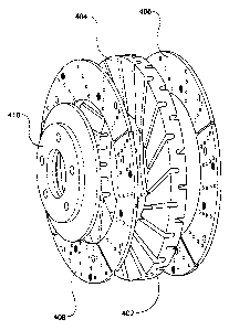
100481 FIG. 7 is an exploded view in isometric view of the major components of
the vented
brake rotor of this embodiment of the instant invention, showing how the
component parts are to
be assembled with respect to one another. In particular, Figure 7 shows how
the plurality of
segmented friction plates are arranged with respect to one another to form the
first and second
braking surfaces of the rotor. Brake rotor substrate body 402 has first (not
shown) and second
friction plate carriers 404 that support the friction plates 406, 408. Hat
region 410 mounts
within the central portion of the brake rotor substrate body.
[00491 FIG. 8 is an isometric view of the assembled vented brake rotor. In
particular, it shows a
plurality of friction plates 406a, 406b, 406c, 406d attached to the first
friction plate carrier
surface of the brake rotor substrate body 402, thereby forming a first braking
surface 502. The
attachment is by means of fasteners 504. Note that through-holes 316a, 318a,
320a and 322a
line up with channel 506, meaning that each of these through-holes is in fluid
communication
with channel 506. This means that air can flow into channel 506 at the inner
circumferential
surface, pass through holes 316a, 318a, 320a and 322a and exit at first
braking surface 502,
11
CA 02769431 2012-02-29
exchanging heat all along the way. During braking, each through hole also
passes over a brake
pad, so heat can also be directly extracted from the contact area between the
brake pad and
friction surface, thereby helping to cool the brake pads as well.
[0050] The preceding description of embodiments provide examples of the
present invention.
The embodiments discussed herein are merely exemplary in nature, and are not
intended to limit
the scope of the invention in any manner. Rather, the description of these
embodiments and
methods serves to enable a person of ordinary skill in the relevant art to
make, use and perform
the present invention.
INDUSTRIAL APPLICABILITY
[0051] The vented brake rotor and segmented brake rotor carrier platform of
the instant
invention will provide the following benefits over known vented brake rotors;
however, not all
embodiments will necessarily feature all of these benefits.
Improved Cooling
[0052] The EVR carrier or platform provides increased directional cooling air
flow directly
under the friction plates. This benefits rotor performance in two ways: by
dissipating heat
directly from the friction plates through the vent channels and reducing the
heat storage in the
rotor carrier platform. Further, heat stored in the light weight carrier can
be dissipated quickly
due to its greater mass and heat transfer design. Such storage and dissipation
of heat is critical to
broadening and maintaining the brake within its optimal performance range.
[0053] The "directional fins" embodied in the EVR patent, which operate as fan
blades, increase
the volume and velocity of cooling air through the cooling vents, thereby
significantly
increasing the cooling capacity and decreasing the associated heat build-up in
the friction wear
segments and platform or carrier.
12
CA 02769431 2012-02-29
[0054] The friction plates, cross-drilled (can be a variety of shapes and
sizes, slots, ovals,
circular etc) such that a series of cooling holes are placed, as required by
application, through the
friction plate area further increases the dissipation of heat from the
friction plates. The size and
shape flexibility is important to allow the part to be "tuned" to eliminate
noise frequency that
can develop.
[0055] The air cooling channels can be made, as provided in U.S. Patent No.
6,536,564 with a
"primary channel" and "secondary channels", or with one uniform single
channel. The channel
design flexibility enables application specific design to address cooling,
structural integrity, heat
location management(i.e., if there is significantly greater heat in the outer
edge region of the
rotor segments)
[0056] Brake rotors are all cooled by convection, radiation and conductive
heat dissipation. All
three of these properties are improved by the invention's design and will
result in:
= Reduced brake fade;
= Greater brake pad and rotor life;
= Less thermal distortion from heat build up which results in warping and
coning
causing vibration and judder;
= Extended component life from reduced heat transfer to wheel, axle hub and
bearing
components; and
= Reduced metal fatigue and thermal cracking.
One and Two-Piece design
[0057] The flexibility of providing segmented rotor carriers in a one-piece
design, where the
mounting hat and friction segment carrier are integrated and a two-piece
design, where the hat
and friction segment carrier are two separate attached components provides
complete flexibility
of application and manufacture. The utilization of a two-piece design enables
common carrier
sizes to be mated to different mounting hat dimensions, providing greater
fitment flexibility and
reducing manufacturing costs by reducing the number of size dependent molds,
inventory SKUs
and all related ancillary costs such as freight, warehousing etc.
13
CA 02769431 2012-02-29
[00581 It is common that brake rotors, under high heat, warp, fade and
generally lose braking
effectiveness, sometimes referred to as judder or thermal judder. One of the
primary cause of
this judder is "Coning" or "Cupping" caused when the friction ring bends
toward the hub region
(inboard). The utilization of a two-piece design substantially eliminates this
cupping, greatly
improving the performance of the rotor, or segmented rotor.
Reduced manufacturing cost and manufacturing flexibility
[00591 The externally vented design embodied by U.S. Patent No. 6,536,564
provides important
lower cost manufacturing when compared to traditional internal cooling channel
designs used in
segmented brake rotors. This results from the elimination of mold inserts
(sand, clay or
mechanical fingers) used to create common internal vent designs in alloy
segmented rotors.
[00601 The externally vented design benefits from the flexibility to machine
the rotor carrier to
variable thickness requirements without concern for the limitations on
structural integrity
inherent in the internally vented rotor.
Other Economic Benefits
[00611 The other large benefit is the logistical advantage to reduce shipping
costs initially and
create a secondary market of re-buildable rotor disc platforms with
replaceable wear plates with
fasteners in a box that costs even less to ship to the users/customers who
include military,
commercial, and vocational end-users.
Light Weight
[00621 The alloy based SBR "carrier" as contemplated by this invention,
embodies the structural
integrity to absorb high stress while providing a significant weight reduction
over common cast
iron based segmented rotors.
14
CA 02769431 2012-02-29
100631 The reduced weight of the rotor will reduce rotating mass and vehicle
unsprung weight,
allowing for overall vehicle weight reduction or redistribution of weight to
critical component
areas, such as batteries in hybrid vehicles.
[00641 An artisan of ordinary skill will appreciate that various modifications
may be made to the
invention herein described without departing from the scope or spirit of the
invention as defined
in the appended claims.