Language selection

Search

Patent 2769502 Summary

Third-party information liability

Some of the information on this Web page has been provided by external sources. The Government of Canada is not responsible for the accuracy, reliability or currency of the information supplied by external sources. Users wishing to rely upon this information should consult directly with the source of the information. Content provided by external sources is not subject to official languages, privacy and accessibility requirements.

Claims and Abstract availability

Any discrepancies in the text and image of the Claims and Abstract are due to differing posting times. Text of the Claims and Abstract are posted:

  • At the time the application is open to public inspection;
  • At the time of issue of the patent (grant).
(12) Patent Application: (11) CA 2769502
(54) English Title: METHOD FOR SEPARATING MAGNETIZABLE PARTICLES FROM A SUSPENSION AND ASSOCIATED DEVICE
(54) French Title: PROCEDE DE SEPARATION DES PARTICULES MAGNETISABLES D?UNE SUSPENSION ET DISPOSITIF ASSOCIE
Status: Deemed Abandoned and Beyond the Period of Reinstatement - Pending Response to Notice of Disregarded Communication
Bibliographic Data
(51) International Patent Classification (IPC):
  • B03C 1/28 (2006.01)
  • B03C 1/033 (2006.01)
(72) Inventors :
  • HARTMANN, WERNER (Germany)
  • KRIEGLSTEIN, WOLFGANG (Germany)
(73) Owners :
  • BASF SE
  • SIEMENS AKTIENGESELLSCHAFT
(71) Applicants :
  • BASF SE (Germany)
  • SIEMENS AKTIENGESELLSCHAFT (Germany)
(74) Agent: SMART & BIGGAR LP
(74) Associate agent:
(45) Issued:
(86) PCT Filing Date: 2010-07-23
(87) Open to Public Inspection: 2011-02-03
Examination requested: 2015-03-17
Availability of licence: N/A
Dedicated to the Public: N/A
(25) Language of filing: English

Patent Cooperation Treaty (PCT): Yes
(86) PCT Filing Number: PCT/EP2010/060683
(87) International Publication Number: WO 2011012539
(85) National Entry: 2012-01-27

(30) Application Priority Data:
Application No. Country/Territory Date
10 2009 035 416.6 (Germany) 2009-07-31

Abstracts

English Abstract

In a method for separating magnetisable particles from a suspension, the suspension is passed through a cylinder-symmetrical separator wherein the substance streams are separated by means of at least one tubular separation screen. According to the invention, the separator separates the substance stream into a concentrate as well as a so-called tailing and the control of the separation rate of the concentrate and tailing is carried out solely by controlling the flow rate. To this end, at least one separation screen (11, 21) is displaceable in the separator (10, 20), so that a variable gap (15, 25) is formed.


French Abstract

L?invention concerne un procédé de séparation des particules magnétisables d?une suspension, la suspension étant transportée à travers un séparateur cylindrosymétrique dans lequel a lieu une séparation des flux de matières par l?intermédiaire d?un écran de séparation au moins de forme tubulaire. Selon l?invention, le flux de matières, en passant dans le séparateur, est séparé en un concentré d?une part et en un résidu (gangue) d?autre part, le taux de séparation concentré/résidu n?étant influencé que par le débit. En outre, au moins un écran de séparation (11, 12) est mobile dans le séparateur (10, 20), de telle sorte qu?une fente variable (15, 25) soit formée.

Claims

Note: Claims are shown in the official language in which they were submitted.

1
Claims
1. A device for separating magnetizable particles from a
suspension that is present in the form of a material flow and
contains metallic and non-metallic fractions and has a
predefined mass flow rate, the device comprising a
longitudinally symmetrical magnetic separator which for
separation of the material flows has at least one separating
gap which has a variable gap width, characterized in that an
at least partially tubular separating screen (11, 21) is
provided for adjusting the separating gap (15, 25), the at
least one separating screen (11, 21) being adjustable in the
circumferential direction of the longitudinally symmetrical
separator (1, 2), electronic control elements being provided
for adjusting the gap width of the separator (1, 2), which
electronic control elements receive as a control variable a
signal which can be obtained from the magnetite quantity
contained in parts of the material flow or in the material
flow relating to the volume-based magnetizability thereof.
2. The device as claimed in claim 1, characterized in that
the separating screen (11) is segmented, two segments (11',
11'', 11''') at least partially overlapping in pairs in each
case (Fig. 2).
3. The device as claimed in claim 1, characterized in that
the separating screen (21) is axially displaceable.
4. The device as claimed in claim 1, characterized in that
the separator (1, 2) is cylindrically symmetrical and has a
circular cross-section.

5. The device as claimed in claim 2, characterized in that
the individual segments (11) are moved by means of connecting
link-like, circular segment-shaped guides (12) which form
acentric control cams.
6. The device as claimed in claim 5, characterized in that
an approximately closed external contour is always achieved
during the movement of the acentric control cams (12).
7. The device as claimed in claim 1, characterized in that
in the cylindrically symmetrical separator the space between
the external contour and the separator inner wall forms a
separating gap (25) which is variable in width and which can
be used as a wedge-shaped screen (21) for varying the
concentrate stream independently of other method parameters.
8. The device as claimed in claim 7, characterized in that
the wedge-shaped separating screen (21) is arranged so as to
be displaceable in the cylindrically symmetrical separator,
such that a larger or smaller separating gap (25) forms for
separating the concentrate depending on the position of the
screen (21).
9. The device as claimed in claim 6, characterized in that
the wedge-shaped separating screen (21) is arranged so as to
be displaceable in the flow direction or against the flow
direction.
10. The device as claimed in claim 7, characterized in that
the incline of the wedge-shaped separating screen (21) faces
toward the inner wall of the cylindrically symmetrical
separator.

Description

Note: Descriptions are shown in the official language in which they were submitted.


CA 02769502 2012-01-27
PCT/EP2010/060683 / 2008P23247WO
1
Description
Method for separating magnetizable particles from a suspension
and associated device
The invention relates to a method as claimed in the preamble
of claim 1. In addition the invention relates to a device for
carrying out said method.
In'the ore mining industry rock containing ore fractions in
the percentage range is extracted, from which a valuable
material concentrate must be obtained. In the prior art this
is effected in practice in a purely mechanical manner by way
of what are known as floating aggregates. Magnetic separation
is also proposed. In the case of magnetic separation within
the context of ore extraction there exists the requirement to
separate magnetizable particles, and where applicable
agglomerates of magnetizable particles with mineral particles,
in particular valuable ore particles, from other mineral
particles which are contained in the same suspension (pulp) by
means of magnetic fields. In particular it is required that
this is done in a continuous process in order to manage the
desired high mass flow rates of typically 1000 m3/h and more.
Magnet arrangements have already been described which allow a
concentrated pulp stream, what is known as the concentrate, in
which the magnetizable particles are present in high
concentration, to be obtained in proximity to the wall of the
magnet system of a tubular or gap-like separating reactor,
which is generally called a separator. The depleted mass
stream (tailing) flows in the remaining tube or gap volume,
and accordingly the task is to separate this from the valuable
material stream. Since both mass flow rate and particle

CA 02769502 2012-01-27
PCT/EP2010/060683 / 2008223247W0
2
concentrations may be subject to strong variations, the
separation of concentrate and tailing must be able to
compensate for correspondingly large variations in the partial
mass streams.
Until now no continuously operating ore separation methods
have existed in practice in which a corresponding separation
of concentrate and tailing is performed. It is proposed to
accomplish the separation through lateral extraction of the
concentrate by way of a corresponding pipe socket, it being
possible to influence the separation rate only by influencing
the flow rate, for example by way of additional pumps or
restriction of the volume flow. It is furthermore proposed
that in a cylindrically symmetrical arrangement the separation
of the concentrate and tailing material flows is performed by
way of a tubular separating screen. In this case, however, the
diameter of the separating screen generally cannot be changed,
so the ratio of the concentrate-tailing flow rates can
similarly only be influenced through control of the mass flow
rate. It is therefore necessary to disclose a separating
screen construction by means of which the ratio of the volume
flow rates is easily and reliably controlled as a function of
corresponding control variables so that the overall process
always executes in an optimal manner.
From this starting point it is the object of the invention to
propose an improved method and to create suitable devices for
separating material flows containing magnetizable particles.
The object is achieved according to the invention by the
measures of claim 1. An associated device for carrying out the
inventive method is disclosed in claim 11. Developments of the
invention are the subject matter of the dependent claims. The

CA 02769502 2012-01-27
PCT/EP2010/060683 / 2008P23247WO
3
specific mode of operation of the device in particular may
also be derived therefrom.
Within the context of the invention it is proposed to use, in
particular in a tubular or tubular gap-shaped arrangement, a
separating screen which is segmented in the circumferential
direction and in which segments partially overlap in pairs in
each case, the individual segments being moved on circular,
acentric control cams in such a way that an approximately
closed external contour is always achieved. In this case the
space between said external contour and the separator inner
wall forms a separating gap which can be varied in width and
with the aid of which the concentrate stream can be changed
independently of other method parameters.
Alternatively a wedge-shaped separating screen can be arranged
in a corresponding separator so as to be displaceable in or
against the flow direction, such that a larger or smaller
separating gap forms for separating the concentrate depending
on the position of the screen. The incline of the separating
wedge faces toward the inner wall of the separator, such that
the gap located therebetween at the end of the separator can
be enlarged or reduced by way of this axial displacement. This
may be implemented in all conceivable flow cross-sections, in
rectangular gaps and in rotationally symmetrical arrangements
or in tubes with a non-circular cross-section.
The following advantages result from the invention:
a continuous edge is produced by the annular, nested tubular
segments, which may, for example, be circular segment
control cams,

CA 02769502 2012-01-27
PCT/EP2010/060683 / 2008P23247WO
4
- the control cams are controlled by way of a common cam disk,
thereby producing an approximately closed external contour,
- the external radius matches the internal radius of the
separator gap,
the edges of the segments can be provided with hard metal,
hard ceramic or another form of wear protection against
abrasion due to the mineral solid fraction of the pulp, and
this is also possible with an axially displaced, one-piece
separating screen,
- alternatively a separating screen which is conically shaped
toward the magnet-side surface of the separating gap can be
axially displaced in order thereby to enlarge or reduce the
separating gap in a particularly easy manner,
- the separator gap width can be adjusted by way of
electromechanical actuating elements which are controlled by
an electronic controller. As a control variable the
electronic controller receives a signal which can be
obtained from the magnetite quantity contained in the
partial streams or the output mass stream relating to the
volume-based magnetizability thereof.
Further details and advantages of the invention will emerge
from the following figure-related description of exemplary
embodiments with reference to the drawing and in conjunction
with the claims.
In the figures, in each case in a schematic view,
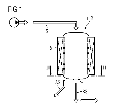
Fig. 1 shows a magnetic separator,
Fig. 2 shows the cross-section of a magnetic separator with
azimuthally adjustable screens, and

CA 02769502 2012-01-27
PCT/EP2010/060683 / 2008P23247WO
Fig. 3 shows a longitudinal section through a separator
according to Fig. 1 with an axially adjustable screen
device.
In Fig. 1 reference numeral 1 designates a separator which is
symmetrical to a longitudinal axis I. The separator preferably
has a round cross-section, although it may also have a
rectangular or square cross-section. Located on the separator
1 is a magnetic device which in practice is formed by a coil
as an electromagnet for electrically activatable
magnetization. Other mechanical magnetic devices are also
possible.
A material flow S which consists of an ore with magnetizable
particles and other substances is conveyed into the separator
by means of a pump or the like. The material flow is to be
separated into a valuable material concentrate and a residual
gangue (tailing).
In the prior art a material flow is separated in practice into
a valuable material concentrate and a residual gangue
predominantly according to what is known as the floating
principle, wherein the different substances are separated by
means of flowing liquids. If magnetic separation is to be
performed, it must be ensured that the metallic particles of
the crude ore are rendered magnetizable following grinding to
particles of less than 1 pm. In the case of copper ores, in
which the metallic part is bound in particular as copper
sulfide, this can be achieved in that magnetizable iron ore
components, in particular in the form of magnetite (Fe2O3),
accumulate on the copper sulfide particles. Reference is made
specifically in this regard to the relevant patent
applications of the applicant.

CA 02769502 2012-01-27
PCT/EP2010/060683 / 2008P23247WO
6
In Fig. 2 reference numeral 10 designates the tube wall of the
separator 1 from Fig. 1. The section is made in the lower
region of the separator 1. It can be seen that a separating
screen 11 is present which consists of three part-screens 11',
11'', 11.. which overlap around the circumference. The part-
screens 11', 1111, 11"1 can each be pivoted about a guide
axis 12', 1211, 12"' which are in turn each guided in a
connecting link 12 as an acentric guide cam. A gap 15 is
formed between the separating part-screens 11', 11'', 11"' in
each case. The width of the gap 15 can be varied externally
and adjusted to the particular requirements in particular by
way of an electric controller.
The fraction. of the material flow discharged as valuable
material concentrate can therefore be influenced by the
current width of the gap 15. The residual gangue, what is
referred to as the tailing, is discharged in the central part.
In the case of a cylindrically symmetrical construction of the
separator according to Fig. 2, a displacer (which is not shown
specifically in Fig. 2) may be present in order.to improve
efficiency. Separation of the material flow into valuable
material and tailing is improved thereby.
In Fig. 3 a tube wall of the separator 1/2 from Fig. 1 is
designated by reference numeral 20. The longitudinal section
in the lower region is shown here. In this embodiment variant
a screen device 21 is arranged therein so as to be axially
displaceable, a gap 25 being produced between screen 21 and
tube inner wall 20 of the separator 2. The screen device is
embodied therein in such a way that the circumferential gap 25
is changed with the axial displacement. The fraction of the

CA 02769502 2012-01-27
PCT/EP2010/060683 / 2008P23247WO
7
material flow is again channeled out at the circumference
thereby and a variable value flow created.
In Fig. 3 a wear protection mechanism 22 is arranged on the
surface of the separating screen 21. A coil 35 can also be
seen here as part of the magnetic device 5 from Fig. 1 with
which suitable magnetic fields can be produced for the
intended purpose.
It can be shown that with appropriate conditioning of the
material flow by means of the magnetic activation the
magnetizable particles are enriched at the circumference of
the cylindrically symmetrical separator. Thus, efficient
separation is possible by virtue of the magnetic activation.
Separation rates of up to 85 % can be achieved.
A further enrichment can be accomplished if the tailing passes
through a further magnetic separating device. A cascade-like
arrangement of magnetic separators according to Fig. 2 or Fig.
3 is also possible.

Representative Drawing
A single figure which represents the drawing illustrating the invention.
Administrative Status

2024-08-01:As part of the Next Generation Patents (NGP) transition, the Canadian Patents Database (CPD) now contains a more detailed Event History, which replicates the Event Log of our new back-office solution.

Please note that "Inactive:" events refers to events no longer in use in our new back-office solution.

For a clearer understanding of the status of the application/patent presented on this page, the site Disclaimer , as well as the definitions for Patent , Event History , Maintenance Fee  and Payment History  should be consulted.

Event History

Description Date
Time Limit for Reversal Expired 2017-07-25
Application Not Reinstated by Deadline 2017-07-25
Inactive: Abandoned - No reply to s.30(2) Rules requisition 2016-09-23
Deemed Abandoned - Failure to Respond to Maintenance Fee Notice 2016-07-25
Inactive: S.30(2) Rules - Examiner requisition 2016-03-23
Inactive: Report - No QC 2016-03-21
Letter Sent 2015-03-27
Request for Examination Received 2015-03-17
All Requirements for Examination Determined Compliant 2015-03-17
Request for Examination Requirements Determined Compliant 2015-03-17
Change of Address or Method of Correspondence Request Received 2015-01-15
Amendment Received - Voluntary Amendment 2014-04-07
Inactive: Cover page published 2012-04-04
Inactive: Notice - National entry - No RFE 2012-03-13
Inactive: IPC assigned 2012-03-09
Application Received - PCT 2012-03-09
Inactive: IPC assigned 2012-03-09
Inactive: First IPC assigned 2012-03-09
National Entry Requirements Determined Compliant 2012-01-27
Application Published (Open to Public Inspection) 2011-02-03

Abandonment History

Abandonment Date Reason Reinstatement Date
2016-07-25

Maintenance Fee

The last payment was received on 2015-06-05

Note : If the full payment has not been received on or before the date indicated, a further fee may be required which may be one of the following

  • the reinstatement fee;
  • the late payment fee; or
  • additional fee to reverse deemed expiry.

Please refer to the CIPO Patent Fees web page to see all current fee amounts.

Fee History

Fee Type Anniversary Year Due Date Paid Date
Basic national fee - standard 2012-01-27
MF (application, 2nd anniv.) - standard 02 2012-07-23 2012-06-06
MF (application, 3rd anniv.) - standard 03 2013-07-23 2013-06-07
MF (application, 4th anniv.) - standard 04 2014-07-23 2014-06-23
Request for examination - standard 2015-03-17
MF (application, 5th anniv.) - standard 05 2015-07-23 2015-06-05
Owners on Record

Note: Records showing the ownership history in alphabetical order.

Current Owners on Record
BASF SE
SIEMENS AKTIENGESELLSCHAFT
Past Owners on Record
WERNER HARTMANN
WOLFGANG KRIEGLSTEIN
Past Owners that do not appear in the "Owners on Record" listing will appear in other documentation within the application.
Documents

To view selected files, please enter reCAPTCHA code :


To view images, click a link in the Document Description column. To download the documents, select one or more checkboxes in the first column and then click the "Download Selected in PDF format (Zip Archive)" or the "Download Selected as Single PDF" button.

List of published and non-published patent-specific documents on the CPD .

If you have any difficulty accessing content, you can call the Client Service Centre at 1-866-997-1936 or send them an e-mail at CIPO Client Service Centre.


Document
Description 
Date
(yyyy-mm-dd) 
Number of pages   Size of Image (KB) 
Description 2012-01-27 7 255
Claims 2012-01-27 2 70
Drawings 2012-01-27 2 38
Abstract 2012-01-27 1 16
Representative drawing 2012-01-27 1 4
Cover Page 2012-04-04 1 37
Description 2014-04-07 9 315
Claims 2014-04-07 4 135
Abstract 2014-04-07 1 15
Notice of National Entry 2012-03-13 1 193
Reminder of maintenance fee due 2012-03-26 1 112
Reminder - Request for Examination 2015-03-24 1 115
Acknowledgement of Request for Examination 2015-03-27 1 174
Courtesy - Abandonment Letter (Maintenance Fee) 2016-09-06 1 172
Courtesy - Abandonment Letter (R30(2)) 2016-11-07 1 163
PCT 2012-01-27 20 674
Correspondence 2015-01-15 2 63
Examiner Requisition 2016-03-23 4 244