Note: Descriptions are shown in the official language in which they were submitted.
CA 02769730 2013-07-30
SYNTHETIC STRUCTURE FOR SOFT TISSUE REPAIR
BACKGROUND
1. Technical Field
Synthetic structures for the repair of soft tissue are described. Such
structures
may include, in embodiments, fibrillar structures that may be utilized to
approximate the
physical characteristics of soft tissue and thus may be useful as implants to
promote the
repair of soft tissue.
2. Background
There are currently several ways in which various types of soft tissues such
as
ligaments or tendons, for example, are reinforced and/or reconstructed, such
as,
bioprosthetic techniques or synthetic techniques. Bioprosthetic techniques
include, for
example: autografting, where tissue from the patient's body is used;
allografting, where
donor tissue from the same species is utilized; and, xenografting, in which
tissue from a
donor of a different species is used. Other bioprosthetic techniques for soft
tissue
attachment, reinforcement, and/or reconstruction have included small
intestinal
submucosa (SIS) or other naturally occurring extracellular matrix (ECM), and a
naturally
CA 02769730 2012-01-31
WO 2011/014755
PCT/US2010/043881
occurring ECM or ECM component. Bioprosthetic techniques may be used alone or
in
conjunction with synthetic devices for tissue repair.
Synthetic techniques of tissue reconstruction, reinforcement and repair do not
utilize donor material. Mechanical techniques such as suturing the torn or
ruptured ends
of the tissue are used to restore function. Sutures may be reinforced through
other
synthetic non-bioabsorbable or bioabsorbable materials.
One example of a material often used in conjunction with sutures in tissue
repair
is a surgical mesh. Surgical meshes may be used to support and/or reinforce
damaged or
weakened portions of the body. Surgical meshes may also be used as a scaffold
for tissue
regeneration. In this regard, the mesh must be sufficiently porous to allow
for growth of
tissue through the mesh after implantation. The healing tissue grows through
porous
openings in the implanted mesh, thereby assimilating the mesh and adding
structural
integrity to the tissue. Surgical meshes may also be utilized in tendon
repair. Tendons of
the body are under continuous movement causing stress and tension or pulling
in the
tendon. Accordingly, surgical meshes used in tendon repair should exhibit
sufficient
yield and tensile strength to endure the weight and stress or strain put on
the tendon.
However, the mesh should also be flexible and pliable enough to move with the
tendon
without breaking. The mesh should also be suturable and have a high suture
pullout
strength to allow the implant to function properly in vivo.
Various surgical meshes attempt to provide strength by knitting, weaving,
braiding, or otherwise forming a plurality of yarns into a support trellis.
These meshes
may be produced with monofilament or multifilament yarns made of materials
such as
2
CA 02769730 2012-01-31
WO 2011/014755
PCT/US2010/043881
polypropylene and polyester. Surgical mesh formed of monofilament yarn
provides
satisfactory reinforcement ability, but is often stiff and has limited
pliability.
SUMMARY
The present disclosure provides an implant, which includes a multi-layer
planar
fibrillar structure wherein the layers of the fibrillar structure are
intermittently secured to
each other on at least one edge portion. The multi-layer planar fibrillar
structure of the
implant may approximate mechanical properties of soft tissue. The multi-layer
planar
fibrillar structure may include two layers. The edge portion of the implant
may be
intermittently secured by intermittent ultrasonic welds. In embodiments, two
opposing
edge portions of the multi-layer planar fibrillar structure are intermittently
secured. In
embodiments, the multi-layer planar fibrillar structure includes two unsecured
opposing
edge portions.
In embodiments, the multi-layer planar fibrillar structure of the implant is
bioabsorbable. In embodiments, the bioabsorbable multi-layer planar fibrillar
structure is
fabricated from glycolide, lactide, trimethylene carbonate, dioxanone,
caprolactone,
alkylene oxides, ortho esters, collagen, hyaluronic acids, alginates, and/or
combinations
thereof.
In embodiments, the multi-layer planar fibrillar structure of the implant is
non-
bioabsorbable. The non-bioabsorbable multi-layer planar fibrillar structure
may be
fabricated from polypropylene, polyethylene, polyamide, polyalkylene
therephalate,
polyvinylidene fluoride, polytetraflouroethylene and/or combinations thereof.
3
CA 02769730 2012-01-31
WO 2011/014755
PCT/US2010/043881
In embodiments, the multi-layer planar fibrillar structure is adapted to
approximate the mechanical properties of a human tendon and/or a human
ligament. In
embodiments, multi-layer planar fibrillar structure is has a stiffness of from
about 10 to
about 500 Newtons per millimeter. In embodiments, the multi-layer planar
fibrillar
structure has a tensile strength of from about 20 to about 2000 Newtons. In
embodiments,
the multi-layer planar fibrillar structure is has a failure strain at from
about 105% to about
170% of its original length.
In embodiments, the multi-layer planar fibrillar structure has from about 10
to
about 200, e.g. about 150, warp fibers per inch. At least one layer of the
multi-layer
planar fibrillar structure may be felt, knitted, woven, or non-woven.
The multi-layer planar fibrillar structure may include least one fiber having
a
diameter from about 10 microns to about 200 microns or multi-layer planar
fibrillar
structure may include at least two fibers of different diameters.
The multi-layer planar fibrillar structure may have a suture pullout strength
from
about 80 N to about 1200 N per centimeter of structure width. In embodiments,
the
suture pullout strength may be, e.g., about 350 N per centimeter of structure
width.
The multi-layer planar fibrillar structure may include a bioactive agent.. In
embodiments, the bioactive agent is within at least one secured edge portion.
In
embodiments, the implant includes three layers wherein the middle layer
contains a
bioactive agent. The middle layer may be secured between the layers of the
multi-layer
planar fibrillar structure or the middle layer may not be secured. In
embodiments, the
middle layer is non-woven, woven, knitted, hydrogel, or combinations of these.
In
4
CA 02769730 2012-01-31
WO 2011/014755
PCT/US2010/043881
embodiments, the middle layer is felt. In embodiments the bioactive agent
includes
platelet-rich plasma, bone marrow, growth factor and combinations of these.
The present disclosure also provides an implant having a multi-layer planar
fibrillar structure having a first woven layer; a felt middle layer; and a
second woven
layer. The first and second woven layers are intermittently secured to each
other on at
least one edge portion. In embodiments, the middle layer includes a bioactive
agent
selected from platelet-rich plasma, bone marrow, growth factor and
combinations thereof.
The present disclosure further includes a method of treating soft tissue. The
method includes providing an implant comprising a multi-layer planar fibrillar
structure
wherein the layers of said fibrillar structure are intermittently secured on
at least one edge
portion and affixing the fibrillar structure to the soft tissue or portions
thereof. The soft
tissue may be a tendon or a ligament. In embodiments, the fibrillar structure
is adapted to
approximate mechanical properties of a human tendon or a human ligament.
The present disclosure also includes a method of replacing soft tissue
including
providing an implant comprising a multi-layer planar fibrillar structure
wherein the layers
of said fibrillar structure are intermittently secured on at least one edge
portion and
affixing the fibrillar structure to a member to muscle, bone, ligament,
tendon, and/or
portions thereof. The fibrillar structure may approximate the mechanical
properties of a
tendon or a ligament. In embodiments, the tendon or ligament is a human tendon
or a
human ligament.
The present disclosure also includes a method of manufacturing an implant
including providing a first planar fibrillar structure having at least one
edge portion,
providing a second planar fibrillar structure having at least one edge
portion; and
5
CA 02769730 2012-01-31
WO 2011/014755
PCT/US2010/043881
intermittently securing edge portions of the first planar fibrillar structure
to the edge
portion of the second planar fibrillar structure to form an implant having at
least one
intermittently secured edge portion. The intermittently securing may be
intermittently
welding. The method further includes providing a third planar fibrillar
structure, which
includes a bioactive agent and positioning it between the first and second
planar fibrillar
structures. The third planar structure may be felt and the bioactive agent may
be platelet
rich plasma, bone marrow, growth factors and combinations of these.
BRIEF DESCRIPTION OF DRAWINGS
Figure 1 is a top view of one embodiment of an implant of the present
disclosure
having opposing parallel edge portions intermittently secured;
Figure 2 is a side view of one embodiment of an implant of the present
disclosure
having a through-hole between unsecured edge portions;
Figure 3 shows a theoretical strain-stress curve for a biological tissue; and
Figure 4 is a side view of one embodiment of an implant of the present
disclosure
having three layers.
DETAILED DESCRIPTION OF PREFERRED EMBODIMENTS
A synthetic implant for soft tissue repair may include a multi-layer planar
fibrillar
structure that is adapted to approximate mechanical properties of soft tissue.
In
embodiments, the fibrillar structure may be a multi-layer planar structure
which is
adapted to approximate the mechanical properties of a tendon and/or ligament.
In
6
CA 02769730 2012-01-31
WO 2011/014755
PCT/US2010/043881
embodiments, the multi-layer planar fibrillar structure is adapted to
approximate the
mechanical properties of a htunan ligament and/or human tendon.
In embodiments, the formation of an intermittently secured edge portion of the
multi-layer planar fibrillar structure provides a fibrillar structure of the
present disclosure
with enhanced strength at the point of attachment and may minimize the chance
that the
fibrillar structure of the present disclosure may become detached from the
sutures or
similar means utilized to affix a fibrillar structure of the present
disclosure to tissue. In
addition, intermittently secured edge portions, in contrast to a continuous
length of
attachment, allow the fibrillar structure to be more flexible, especially in
the edge portion.
The mechanical properties of soft tissue and/or the multi-layer planar
fibrillar
structures in accordance with the present disclosure may be determined by any
technique
within the purview of those skilled in the art. For example, mechanical
properties of soft
tissue and/or the fibrillar structures can be determined by placing a sample
in a spring
loaded clamp attached to the mechanical testing device and subjecting the
sample to
constant rate extension (5 mm/sec) while measuring load and displacement and
recording
the resulting strain-stress curve. In embodiments, the multi-layer planar
fibrillar structure
may exhibit a stiffness approximating the stiffness of soft tissue. In
embodiments, a
suitable stiffness may be from about 10 to about 500 Newtons per millimeter
(N/mm),
and suitable tensile strength may be from about 20 to about 2000 Newtons. In
embodiments, the stiffness of the polymeric fibrillar structure will be from
about 20 to
about 80 N/mm. In embodiments, the fibrillar structure may exhibit a failure
strain at
from about 105% to about 160% of its original length.
7
CA 02769730 2012-01-31
WO 2011/014755
PCT/US2010/043881
The fibrillar structure may be prepared using any method within the purview of
those skilled in the art. For example, the fibrillar structure may be woven.
It is also
contemplated that the fibrillar structure could be a non-woven structure,
provided that it
possesses suitable mechanical properties, for example, the stiffness, tensile
strength,
and/or failure strain described above. In embodiments, each layer of the
fibrillar
structure may be woven and include from about 10 to about 200 warp fibers per
inch,
e.g., about 180 fibers per inch, in embodiments from about 30 to about 100
warp fibers
per inch. In embodiments, from about 50 to about 75 warp fibers per inch.
The fibrillar structure may be prepared from fibers having a diameter of from
about 10 microns to about 1.0 mm; in embodiments from about 15 microns to
about 200
microns; in embodiments from about 20 microns to about 50 microns. Each layer
of the
fibrillar structure may be prepared from monofilaments, traditional
multifilament yarns,
or bi-component multifilament yarns. In embodiments each layer of the
fibrillar structure
may be prepared from multiple fibers of at least two different diameters.
The multi-layer planar fibrillar structure can be made from any biocompatible
polymeric material capable of providing suitable mechanical properties. The
biocompatible material may be bioabsorbable, non-bioabsorbable, or a
combination of
bioabsorbable and non-bioabsorbable. Suitable absorbable materials include,
but are not
limited to, glycolide, lactide, trimethylene carbonate, dioxanone,
caprolactone, alkylene
oxides, ortho esters, polymers and copolymers thereof, collagen, hyaluronic
acids,
alginates, and combinations thereof. Suitable non-absorbable materials
include, but are
not limited to, polypropylene, polyethylene, polyamide, polyallcylene
therephalate (such
8
CA 02769730 2012-01-31
WO 2011/014755
PCIAIS21110/043881
as polyethylene therephalate, polybutylene therephalate, and the like),
polyvinylidene
fluoride, polytetraflouroethylene, and blends and copolymers thereof.
In embodiments the each layer of the fibrillar structure may have the same
characteristics, i.e., number of fibers, fiber diameter, absorbability, and
the like. In
embodiments, the characteristics of the layers of the fibrillar structure may
be different.
The layers of the multi-layer planar fibrillar structure are intermittently
secured.
"Intermittently secured" is intended to mean a series of discrete points of
attachment.
Methods of intermittently securing the fibrillar structure may include, for
example,
intermittent ultrasonic welding, intermittent stitching, intermittent gluing,
or intermittent
welding. Securing the layers intermittently allows for secure attachment
between layers
of the fibrillar structure while simultaneously providing flexibility in the
secured edge
portion similar to that in the unsecured edge portions. The discrete points of
attachment
may be arranged linearly in one or more lines, staggered or in any other
pattem.
In embodiments, the layers of the multi-layer planar fibrillar structure may
be
manufactured by providing a first and second fibrillar structure each having
at least one
edge portion and intermittently securing the edge portion of the first planar
fibrillar
structure to the edge portion of the second planar fibrillar structure to form
an implant
having at least one intermittently secured edge. For example, the planar
fibrillar
structures may be sonically welded on opposite edge portions using an
ultrasonic welder.
As another example, the planar fibrillar structures may be intermittently
secured by
intermittent stitching.
9
CA 02769730 2012-01-31
WO 2011/014755
PCT/US2010/043881
As used herein the term "edge portion" includes the outside edge of the
fibrillar
structure to an area recessed therefrom by approximately 10% of the size of
the fibrillar
structure.
The dimensions of the multi-layer planar fibrillar structure may be any
suitable
dimensions. The dimensions of the each layer of the multi-layer planar
fibrillar structure
can vary within those ranges conventionally used for a specific application
and delivery
device. For example, such ranges include dimensions of about 1 centimeter by
about 1
centimeter, to about 15 centimeters by about 15 centimeters. Although
described herein
as square shaped, the planar fibrillar structure may be any geometric shape,
for example,
round, polygonal, square, or oblong. In embodiments, a thin mesh may be formed
having
a thickness from about 0.05 millimeters to about 1.0 millimeters, in
embodiments from
about 0.1 millimeters to about 0.75 millimeters. The present multi-layer
planar fibrillar
structures may advantageously be dimensioned to it to be rolled or otherwise
folded so as
to fit within a cannula having a small diameter to allow arthroscopic or
laparoscopic
implantation. In embodiments, the fibrillar structures in accordance with the
present
disclosure may define openings on the order of from about 0.5 mm to about 2
mm, in
embodiments from about 0.7 mm to about 1.3 mm.
In embodiments, the implant of the present disclosure exhibits a suture
pullout
strength from about 80 N to about 1200 N per centimeter of structure width. In
embodiments, the suture pullout strength may be, e.g., about 350 N per
centimeter of
structure width. As used herein "suture pullout strength" means the maximum
force
required to pull simple loops of sutures through the ends of the multi-layer
planar fibrillar
structure.
CA 02769730 2012-01-31
WO 2011/014755
PCT/US2010/043881
In embodiments, the multi-layer planar fibrillar structure of the present
disclosure
may have two layers. In embodiments, the multi-layer planar fibrillar
structure may have
three or four or more layers. The layers of the multi-layer planar fibrillar
structure of the
present disclosure may include at least one edge portion intermittently
secured. In
embodiments, the intermittently secured edge portion may be referred to as a
"secured
edge portion." The intermittently secured edge portion of the multi-layer
planar fibrillar
structure may be formed by ultrasonic welding. In embodiments, all of the edge
portions
of a multi-layer planar fibrillar structure may be intermittently secured. In
embodiments
edge portions of the multi-layer planar fibrillar structure may be
intermittently secured at
more than one edge portion.
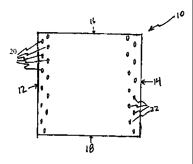
A two layer square embodiment of the multi-layer plarmar fibrillar structure
of the
present disclosure is depicted, for example, in Figure 1. The embodiment of
Figure 1
includes a multi-layer planar fibrillar structure 10 of the present disclosure
having two
layers 24 and 26 (layer 24 not shown). These layers 24, 26 (layer 24 not
shown) include
secured edge portions 12 and 14, and unsecured edge portions 16 and 18. As
depicted in
Figure 1, secured edge portions 12, 14, are intermittently welded along rows
20 and 22 at
numerous points. In embodiments, not shown, multiple rows of intermittent
welding may
be utilized to form the secured edge portions 12, 14 of the multi-layer planar
fibrillar
structure 10. In embodiments, not shown, one or more rows of intermittent
welding may
secure edge portions 16 and 18, of the multi-layer planar fibrillar structure.
In embodiments, two secured edge portions of the multi-layer planar fibrillar
structure may create a through-hole or "tunnel" between the unsecured edge
portions.
The secured edge portions then form the sides of the tunnel. Figure 2, shows a
side view
11
CA 02769730 2012-01-31
WO 2011/014755
PCT/US2010/043881
of the multi-planar fibrillar structure of Figure 1. The layers 24, 26 are
separated along
unsecured edge portions 18 and 16 (edge portion 16 not shown). Edge portions
12 and
14 are secured by intermittent welding 20 and 22 respectively, to form through-
hole 28.
In use, the fibrillar structure may be attached to tissue utilizing any method
within
the purview of those skilled in the art, including the use of fasteners such
as, for example,
staples, barbs, sutures, tacks, adhesives, combinations thereof, and the like.
Returning to
Figure 1, in embodiments, secured edge portion 12 of fibrillar structure 10
may be affixed
to tissue by placing a line of sutures along welded row 20 thereby attaching
edge portion
12 of fibrillar structure 10 to tissue; similarly, secured edge portion 14 of
fibrillar
structure 10 may be affixed to tissue by placing a line of sutures along
welded row 22
thereby attaching edge portion 14 of fibrillar structure 10 to tissue.
It is further contemplated that a bioactive agent may be applied to one or
more
layers of the fibrillar structure. The term "bioactive agent", as used herein,
is used in its
broadest sense and includes any substance or mixture of substances that have
clinical use.
Bioactive agents may or may not have pharmacological activity, e.g., as a dye,
or
fragrance. Alternatively, bioactive agents may provide a therapeutic or
prophylactic
effect. For example, bioactive agents may affect or participate in tissue
growth, cell
growth, cell differentiation, and the like, and may also be able to invoke a
biological
action such as an immune response or play any other role in one or more
biological
processes.
Examples of classes of bioactive agents which may be utilized in accordance
with
the present disclosure include anti-adhesives, antimicrobials, analgesics,
antipyretics,
anesthetics, antiepileptics, antihistamines, anti-inflammatories,
cardiovascular drugs,
12
CA 02769730 2012-01-31
WO 2011/014755
PCT/US2010/043881
diagnostic agents, sympathornimetics, cholinomimetics, antimuscarinics,
antispasmodics,
hormones, growth factors, muscle relaxants, adrenergic neuron blockers,
antineoplastics,
immunogenic agents, immunosuppressants, gastrointestinal drugs, diuretics,
steroids,
lipids, lipopolysaccharides, polysaccharides, and enzymes. It is also intended
that
combinations of bioactive agents may be used.
Suitable antimicrobial agents which may be included as a bioactive agent with
a
fibrillar structure of the present disclosure include triclosan, also known as
2,4,4'-
trichloro-2'-hydroxydiphenyl ether, chlorhexidine and its salts, including
chlorhexidine
acetate, chlorhexidine gluconate, chlorhexidine hydrochloride, and
chlorhexidine sulfate,
silver and its salts, including silver acetate, silver benzoate, silver
carbonate, silver
citrate, silver iodate, silver iodide, silver lactate, silver laurate, silver
nitrate, silver oxide,
silver palmitate, silver protein, and silver sulfadiazine, polymyxin,
tetracycline,
aminoglycosides, such as tobramycin and gentarnicin, rifampicin, bacitracin,
neomycin,
chloramphenicol, miconazole, quinolones such as oxolinic acid, norfloxacin,
nalidixic
acid, pefloxacin, enoxacin and ciprofloxacin, penicillins such as oxacillin
and pipracil,
nonoxynol 9, fusidic acid, cephalosporins, and combinations thereof. In
addition,
antimicrobial proteins and peptides such as bovine lactoferrin and
lactoferricin B may be
included as a bioactive agent with a fibrillar structure of the present
disclosure.
Other bioactive agents which may be included as a bioactive agent with a
fibrillar
structure of the present disclosure include: local anesthetics; non-steroidal
antifertility
agents; parasympathomimetic agents; psychotherapeutic agents; tranquilizers;
decongestants; sedative hypnotics; steroids; sulfonamides; sympathomimetic
agents;
vaccines; vitamins; antimalarials; anti-migraine agents; anti-parkinson agents
such as L-
$3
CA 02769730 2012-01-31
WO 2011/014755
PCT/US2010/043881
dopa; anti-spasmodics; anticholinergic agents (e.g. oxybutynin); antitussives;
bronchodilators; cardiovascular agents such as coronary vasodilators and
nitroglycerin;
alkaloids; analgesics; narcotics such as codeine, dihydrocodeinone,
meperidine, morphine
and the like; non-narcotics such as salicylates, aspirin, acetaminophen, d-
propoxyphene
and the like; opioid receptor antagonists, such as naltrexone and naloxone;
anti-cancer
agents; anti-convulsants; anti-emetics; antihistamines; anti-inflammatory
agents such as
hormonal agents, hydrocortisone, prednisolone, prednisone, non-hormonal
agents,
allopurinol, indomethacin, phenylbutazone and the like; prostaglandins and
cytotoxic
drugs; estrogens; antibacterials; antibiotics; anti-fungals; anti-virals;
anticoagulants;
anticonvulsants; antidepressants; antihistamines; and immunological agents.
Other examples of suitable bioactive agents which may be included with a
fibrillar structure of the present disclosure include viruses and cells,
peptides,
polypeptides and proteins, analogs, muteins, and active fragments thereof,
such as
immunoglobulins, antibodies, cytokines (e.g. lympholcines, monokines,
chemokines),
blood clotting factors, hemopoietic factors, platelet-rich plasma, bone
marrow,
interleulcins (IL-2, IL-3, IL-4, IL-6), interferons (0-1FN and
erythropoietin,
nucleases, tumor necrosis factor, colony stimulating factors (e.g., GCSF, GM-
CSF,
MCSF), insulin, anti-tumor agents and tumor suppressors, blood proteins,
gonadotropins
(e.g., FSH, LH, CG, etc.), hormones and hormone analogs (e.g., growth
hormone),
vaccines (e.g., tumoral, bacterial and viral antigens); somatostatin;
antigens; blood
coagulation factors; extracellular matrix molecules such as fibronectin and
laminin;
hyaluronic acid; collagens; glycosaminoglycans; morphogens; chemoattractants;
growth
factors (e.g., nerve growth factor, insulin-like growth factor, EGF, FGF, PDGF
and
14
CA 02769730 2012-01-31
WO 2011/014755
PCT/US2010/043881
VEGF); protein inhibitors, protein antagonists, and protein agonists; nucleic
acids, such
as antisense molecules, DNA and RNA; oligonucleotides; polynucleotides; and
ribozymes.
The bioactive materials may be applied to the fibrillar structure using any
technique within the purview of those skilled in the art. For example, the
bioactive agent
may be applied to the fibrillar structure of the present disclosure in any
suitable form of
matter, e.g., films, powders, liquids, gels and the like. In embodiments, a
solution of the
bioactive agent in a suitable solvent may be prepared and the solvent driven
off to leave
the bioactive material deposited on the fibrillar structure. A further example
is a
bioactive agent that may be crosslinked around the fibrillar structure so as
to embed one
or more layers of the fibrillar structure within the bioactive agent.
Anti-adhesive agents may be used to prevent adhesions from forming between the
fibrillar structures of the present disclosure and the surrounding tissues.
Some examples
of these agents include, but are not limited to poly(vinyl pyrrolidone),
carboxymethyl
cellulose, hyaluronic acid, polyethylene oxide, poly vinyl alcohols and
combinations
thereof.
Where a secured edge portion of the fibrillar structure is formed, a bioactive
material may also be placed between the layers of the fibrillar structure
prior to
intermittently securing. In this manner, bioactive agents may be released at
the site of
attachment of the fibrillar structure, in embodiments wherein the defect
itself being
treated, thereby enhancing healing of the defect.
In embodiments, the bioactive material may be placed in a tube structure
which,
in turn, is placed between the layers of the multi-layer planar fibrillar
structure. Any
CA 02769730 2012-01-31
WO 2011/014755
PCT/US2010/043881
biocompatible material within the purview of those skilled in the art may be
utilized to
form a tube within which a bioactive material may be placed. Alternatively,
the bioactive
material itself may be tube shaped.
In embodiments, a multi-layer planar fibrillar structure includes one or more
middle layers incorporating a bioactive agent. In embodiments, the one or more
middle
layers may be secured to adjacently disposed layers. In embodiments, the one
or more
middle layers may be intermittently secured to adjacently disposed layers. In
embodiments, the one or more middle layers may be unsecured to adjacently
disposed
layers.
A three-layer multi-layer planar fibrillar structure of the present disclosure
is
depicted, for example, in Figure 4. The three-layer embodiment 30 includes two
fibrillar
layers 32 and 34 that include intermittently secured edge portions 36 and 38.
The middle
layer 40 includes a bioactive agent, such as are described above. In
embodiments, the
bioactive agent in the middle layer 40 is bone marrow. In embodiments, the
bioactive
agent in the middle layer 40 is platelet-rich plasma. In embodiments, the
bioactive agent
may be a combination of platelet rich plasma and bone marrow. The middle layer
40
may be of the same or different material than the two fibrillar layers 32, 34.
For example,
the structure of the middle layer 40 may be non-woven, woven, knit, a
hydrogel, or
combinations thereof. In embodiments, the middle layer is felt. In
embodiments, the
middle layer 40 is intermittently secured to the fibrillar layers 32, 34. In
embodiments,
the middle layer 40 rests between the fibrillar layers 32, 34but is not
secured therein.
Each of the two or more layers of the multi-layer planar fibrillar structure
may
have the same or different mechanical properties, provided that the
combination of the
16
CA 02769730 2012-01-31
WO 2011/014755
PCT/US2010/043881
two or more layers approximates mechanical properties of soft tissue. As used
herein,
"approximates mechanical properties of soft tissue" means close to or exactly
the same as
at least one property of the soft tissue, which is intended to be treated or
replaced. Such
properties include but are not limited to stiffness, modulus of elasticity,
tensile strength,
and the like. In embodiments, each of the two or more layers may have the same
or
different bioabsorbability properties. In embodiments, each of the two or more
layers
may optionally have the same or different bioactive materials applied thereto.
The fibrillar structure may be packaged and sterilized in accordance with any
of
the techniques within the purview of those skilled in the art. The package in
which the
implant or plurality of implants are maintained can take a variety of forms
within the
purview of those skilled in the art. The packaging material itself can be
bacteria and fluid
or vapor impermeable, such as a film, sheet, or tube made of polyethylene,
polypropylene, poly(vinylchloride), poly(ethylene terephthalate), and the
like. Seams,
joints, seals, and the like may be formed in such packaging by conventional
techniques,
such as, for example, heat sealing and adhesive bonding. Examples of heat
sealing
include sealing through the use of heated rollers, sealing through use of
heated bars, radio
frequency sealing, and ultrasonic sealing. Peelable seals based on pressure
sensitive
adhesives may also be used.
The fibrillar structures described herein can be used to treat, i.e., to
repair,
support, and/or reconstruct soft tissue, such as ligaments and tendons. In
embodiments,
the fibrillar structures may rapidly restore mechanical functionality to the
soft tissue. In
embodiments, the fibrillar structure may be used to replace soft tissue.
Mechanical
functionality of a human ligament or human tendon may include a stiffness, for
example,
17
CA 02769730 2012-01-31
WO 2011/014755
PCT/US2010/043881
from about 10 to about 500 Newtons per millimeter (N/mm). Mechanical
functionality of
a human ligament or human tendon may include, for example, a tensile strength
from
about 20 to about 2000 Newtons.
In embodiments, a single layer fibrillar structure is contemplated. One such
single
layer embodiment includes an edge portion having intermittently spaced
ultrasonic welds
to prevent the edge portion of the single layer fibrillar structure from
unraveling. In other
single layer embodiments one or more edges of the single layer fibrillar
structure is
folded over to create an edge portion, and the folded-over edge portion is
intermittently
secured as described above. The materials and characteristics for these single
layer
embodiments are the same as described above for the multi-layer embodiments.
The fibrillar structure may be implanted using conventional surgical or
laparoscopic/arthroscopic techniques. The fibrillar structure may be affixed
to the soft
tissue or to bone adjacent to or associated with the soft tissue to be
repaired. In
embodiments, the fibrillar structure may be affixed to muscle, bone, ligament,
tendon, or
fragments thereof. Affixing the fibrillar structure can be achieved using
techniques within
the purview of those skilled in the art using, fasteners, with or without the
use of anchors,
pledgets, etc.
The present fibrillar structure may be used alone or in combination with other
tissue repair products within the purview of those skilled in the art.
Suitable tissue repair
products that may be used in combination with the present fibrillar structures
include, for
example, RESTORE a small intestine submucosa (SIS) biologic graft material
that is
commercially available from Depuy Orthopedics Inc., Warsaw IN; GRAFTJACICET ,
an
acellular dermal tissue matrix commercially available from Wright Medical
Technology,
18
CA 02769730 2012-01-31
WO 2011/014755
PCT/11S2010/043881
Inc., Arlington, TN; CUFFPATCHTm Type I porcine collagen material from Biomet
Sports Medicine, Inc./Arthrotek (Warsaw, IN); TISSUEMENDe acellular collagen
membrane materials from Stryker (Kalamazoo, MI); and ENCUFFe a cross-linked
pericardium xenograft that has been subjected to an anti-calcification process
commercially available from Selhigh, Inc., Union NJ. Other tissue repair
products
suitable for use in connection with the present fibrillar structures will be
apparent to those
skilled in the art. The other tissue repair product can be separate from or
attached to the
fibrillar structure.
In order that those skilled in the art may be better able to practice the
compositions and methods described herein, the following examples are given as
an
illustration of the preparation of the present compositions and methods. It
should be noted
that the fibrillar structure is not limited to the specific details embodied
in the examples.
EXAMPLES
Ultrasonic Welding Method of Multi-layer planar fibrillar Structure Formation
A multi-layer planar fibrillar structure was intermittently sonically welded
on two
opposite edge portions. The ultrasonic welder used included an actuator and a
power
supply. The actuator was a Branson model #: 921AFS with a 920M Power Supply
Settings for the power supply and actuator are in Table 1 below.
19
CA 02769730 2013-07-30
. ,
Table 1
Part/Setting Example 1 Example 2
Example 3 _
Pressure (PSI) 70 70 70
Welding Time (s) 65 280 350
Hold Time (s) 1 1 1
Trigger Force (lb) 5 9 10
Energy (+) limit 75 N/A N/A
Energy (-) limit 60 N/A N/A
The resulting multi-layer planar fibrillar structure of the disclosure is
represented
in Figure 1.