Note: Descriptions are shown in the official language in which they were submitted.
CA 02769935 2012-02-28
METHOD AND SYSTEM FOR CLEANING FRACTURE PORTS
Field of the Invention
[0002] The present invention is directed to a method and system for cleaning
out or
stimulating fracture ports and the immediate bore hole area.
Background
[0003] An oil or gas well relies on inflow of petroleum products from the
subterranean
formation it intersects. Productive intervals may be left uncased (open hole)
to expose
porosity and permit unrestricted wellbore inflow of petroleum products.
Alternately, the hole
may be cased with a liner, which is then perforated to permit inflow through
the openings
created by perforating.
[0004] Drilling deeper and horizontally into tighter reservoir rock has become
more viable in
many oil and gas bearing formations. However, it is still challenging to
successfully
completing these deeper oil and gas reservoirs using horizontal wells. When
natural inflow
from the well is not economical, the well may require wellbore treatment
termed stimulation.
This is accomplished by pumping stimulation fluids such as fracturing fluids,
acid, cleaning
chemicals or proppant laden fluids to improve wellbore inflow.
[0005] As drilling technology continues to exploit more complex and
unconventional
reservoirs, completion technology is being designed and developed to
effectively stimulate
multiple stages along a horizontal wellbore. The growth in multi-stage
fracturing has been
tremendous due to completion technology that can effectively place fractures
in specific
CA 02769935 2012-02-28
=
2
places in the wellbore. By placing the fracture in specific places in the
horizontal wellbore,
there is a greater ability to increase the cumulative production in a shorter
time frame.
[0006] In a conventional multi-stage fracture completion, Fracture ports are
intermittently
placed along the horizontal wellbore, between open hole packers to isolate
each fracture zone.
Following a fracturing operation, it is often necessary to clean out and re-
stimulate the
fracturing ports and the near bore hole area, if they have plugged or are
suffering from wax,
scale or asphaltene buildup. Near bore hole buildup of organic or inorganic
scale and solids is
referred to as skin damage in the industry. Conventionally, cleaning of
fracture ports and
reversal of skin damage is done by isolating a portion of the production
string including the
fracture port using tubing run isolation packers, and using fluid pressure
and/or chemicals to
stimulate or clean out the open fracture port.
[0007] However, coiled tubing run isolation packers is a time-consuming
process to place, set
and unset the packers. Furthermore, the packers can fail to be set and seal on
the liner. Liners
can have detritus materials like scale, corrosion, and metal and mechanical
debris, which can
cause packers to not set and seal.
[0008] There is a need in the art for alternative and efficient methods of
stimulating or
cleaning fracture ports.
Summary of the Invention
CA 02769935 2012-02-28
3
[0009] In one aspect, the invention comprises a system for stimulating or
cleaning a fracture
port, comprising an assembly configured to be run on coiled tubing, the
assembly comprising
a fluid pulse generator and jetting tool, and not comprising an isolation
packer or seal.
[0010] In another aspect, the invention may comprise a method of stimulating
or cleaning
fracture ports, comprising the steps of inserting a tubing string having a
downhole assembly
configured to be run on coiled tubing, the downhole assembly comprising a
fluid pulse
generator and jetting tool, and not comprising an isolation packer or seal.
Brief Description of The Drawings
[0011] In the drawings, like elements are assigned like reference numerals.
The drawings are
not necessarily to scale, with the emphasis instead placed upon the principles
of the present
invention. Additionally, each of the embodiments depicted are but one of a
number of
possible arrangements utilizing the fundamental concepts of the present
invention. The
drawings are briefly described as follows:
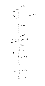
10012] Figure 1 is a schematic view of an oil and gas well having horizontal
section and a
multi-fracture port completion.
[0013] Figure 2 is an exploded view of one embodiment of fluid pulse generator
and jetting
tool.
Detailed Description Of Preferred Embodiments
[0014] The invention relates to a method and system of treating a series of
fracture ports in a
wellbore using a fluid pulse generator and jetting tool. When describing the
present
CA 02769935 2012-02-28
4
invention, all terms not defined herein have their common art-recognized
meanings. To the
extent that the following description is of a specific embodiment or a
particular use of the
invention, it is intended to be illustrative only, and not limiting of the
claimed invention. The
following description is intended to cover all alternatives, modifications and
equivalents that
are included in the spirit and scope of the invention, as defined in the
appended claims.
[0015] As used herein, a "a fluid pulse generator and jetting tool" means a
tool which may be
run into production tubing using coiled tubing, through which a fluid may be
pumped. The
tool comprises at least one jetted opening, and preferably a plurality of
jetted openings, which
emit a fluid stream at a relatively high velocity, and a pulse generator which
creates pressure
pulses in a fluid stream. The fluid pulse generator may also be referred to as
a fluidic
oscillator.
[0016] In embodiments of the invention, a fluid pulse generator and jetting
tool (100) is used
to re-stimulate, or clean out fracture ports and the near bore hole area, by
incorporating the
tool in a wellbore stimulation assembly. The assembly may be a conventional
horizontal
wellbore (12) assembly which can be used to effect fluid treatment of a
formation (10), and
may include a tubing string (14) having a lower end (14a) and an upper end
extending to
surface (not shown). Tubing string (14) includes a plurality of spaced apart
ported intervals
(16a) to (16e) each including a plurality of fracturing ports (17) opened
through the tubing
string wall to permit access between the tubing string inner bore (18) and the
wellbore.
[0017] A packer (20a) is mounted between the upper-most ported interval (16a)
and the
surface and further packers (20b) to (20e) are mounted between each pair of
adjacent ported
CA 02769935 2012-02-28
5 intervals. In the illustrated embodiment, a packer (20f) is also mounted
below the lower most
ported interval (16e) and lower end (14a) of the tubing string. The packers
are disposed about
the tubing string and selected to seal the annulus between the tubing string
and the wellbore
wall, when the assembly is disposed in the wellbore. The packers divide the
wellbore into
isolated segments wherein fluid can be applied to one segment of the well, but
is prevented
from passing through the annulus into adjacent segments. As will be
appreciated the packers
can be spaced in any way relative to the ported intervals to achieve a desired
interval length or
number of ported intervals per segment. In addition, packer (20f) need not be
present in some
applications.
[0018] The packers may be of any construction, such as conventional solid body-
type with at
least one rubber or elastomeric packing element.
[0019] Each of the ports may have a mechanism to open and close the openings,
such as
sliding sleeves. In this embodiment, a sliding sleeve is mounted over each
ported interval to
close them against fluid flow, but can be moved away from their positions
covering the ports
to open the ports.
100201 Conventionally, the assembly is run in and positioned downhole with the
sliding
sleeves each in their closed port position. The sleeves are moved to their
open position when
the tubing string is ready for use in fluid treatment of the wellbore.
Preferably, the sleeves for
each isolated interval between adjacent packers are opened individually to
permit fluid flow to
one wellbore segment at a time, in a staged, concentrated treatment process.
The sleeves may
be actuated by use of a plug or ball inserted into the tubing string, which
may be seated into a
6
.. sealing position and activated by fluid pressure. A suitable apparatus is
described in US
Patent Application No. 2011/0278010 Al.
[0021] The tubing string is run into the well and the packers are placed
between the perforated
intervals. If blast joints are included in the tubing string, they are
preferably positioned at the
same depth as the perforated sections. The packers are then set by mechanical
or pressure
.. actuation. Once the packers are set, stimulation fluids are then pumped
down the tubing
string. The packers will divert the fluids to a specific segment of the
wellbore. A ball or plug
is then pumped to shut off the lower segment of the well and to open a siding
sleeve to allow
fluid to be forced into the next interval, where packers will again divert
fluids into specific
segment of the well. The process is continued until all desired segments of
the wellbore are
.. stimulated or treated. When completed, the treating fluids can be either
shut in or flowed back
immediately.
[0022] The fracture ports are left open to the formation, allowing ingress of
production fluids.
Over time, the fracturing ports may plug or suffer from wax, scale or
asphaltene buildup.
Thus, it is often necessary or desirable to clean out or re-stimulate the
fracture ports.
Conventionally, this is done by isolating a portion of the production string
including the
fracture port using isolation packers run inside the tubing string, and using
fluid pressure
and/or chemicals to stimulate or clean out the open fracture port.
[0023] The applicants have unexpectedly found that a fluid pulse generator and
jetting tool
positioned within the tubing string and adjacent a fracture port may
efficiently clean out a
CA 2769935 2019-07-12
CA 02769935 2012-02-28
7
fracture port, without the need to isolate the interval. Therefore, the system
of the present
invention does not require an isolation packer or seal.
[0024] The fluid pulse generator and jetting tool is a tool which generates
fluid pressure
pulses and a pressurized fluid stream. One embodiment of the tool (100) is
adapted to be run
in on coiled tubing with a bottom hole assembly (102). The tool provides at
least one, and
preferably a plurality of jetted fluid streams, with a pressure pulse
generator.
[0025] In one embodiment, the bottom hole assembly or BHA (102) comprises an
internal
check valve (not shown) and attaches to the tubing in a conventional manner.
The bottom of
the BHA threadingly engages the top of the top jet sub (104) in a conventional
fluid-tight
manner. The other components of the tool are fitted together in top to bottom
order: a top
.. reflective focussing chamber (106), a pulse generator (108), a bottom
reflective focussing
chamber (110), a down jet sub (112), and a nose jet cone (114).
[0026] Both the top jet sub and the bottom jet subs (104, 112) define a
plurality of jetted
openings (116), which preferably are angled towards the ends of the tool. In
one embodiment,
each sub comprises 6 jetted openings located around the periphery of the sub.
[0027] The pulse generator (108) comprises an outer housing (120) and an
internal generator
(122) which defines at least one angled opening. Fluid under pressure which
exits the internal
generator will cause the generator to spin within the outer housing. The outer
housing defines
at least one opening which periodically aligns with the generator angled
opening as the
generator spins within the outer housing. The generator attaches to the top
reflective
CA 02769935 2012-02-28
=
8
focussing chamber (106) and the bottom reflective focussing chamber (110) with
top and
bottom cross-overs (124, 126) respectively.
[0028] Each of the top and bottom reflective focussing chambers comprises an
inner tube
(130) which provides fluid communication between the top jet sub and the
bottom jet sub and
the pulse generator, and a slotted outer tube (132). The outer tube has an
inside diameter
which is slightly larger than the outside diameter of the inner tube, creating
an annular space
therebetween. The outer tube defines a plurality of slots, which preferably
are configured
diagonally such the slot ends are farther away from the pulse generator than
the middle of the
slots. The focussing chambers cause pressure pulses to propagate in the
annular space
between the inner and outer tubes, and reflect back towards the pulse
generator.
[0029] The bottom jet sub is similar to the top jet sub and comprises a
plurality of jetted
openings which are preferably angled away from the pulse generator. The nose
jet cone is
fitted to the bottom end of the tool, and may comprise a jetted opening, which
is preferably
aimed away from tool.
[0030] In use, the tool is run into the production tubing using conventional
coiled tubing
techniques and positioned adjacent a fracture port which is to be treated.
Fluid is pumped
under pressure through the coiled tubing and BHA. Upon reaching the tool
(100), the fluid is
jetted out the jet openings in the top and bottom jet subs, as well as the
nose jet cone. The
fluid also causes rotation of the generator within the pulse generator outer
housing. When the
angled opening aligns with the outer housing opening, a pressure pulse is
emitted from the
CA 02769935 2012-02-28
9
pulse generator. As well, the pressure pulse is accompanied by a simultaneous
pressure drop
at all the jetted openings, resulting in an reverse pressure pulse through the
jet openings.
[0031] The fluid which is pumped through the tool may comprise various
chemistries
designed to remove scale, wax or asphaltene build-up among other objectives,
such as the
breakdown of emulsions and dispersal of formation fines. For example, the
fluid may
comprise an acid, such as hydrochloric acid, which may facilitate dissolution
of iron and
calcium based scales. Organic acids or surfactants may also be effective. The
fluid may
comprise a solvent component which helps remove hydrocarbon components of the
scale,
such as wax or asphaltenes, and may help water wet the reservoir.
[0032] Because of the jet and pulse action of the tool, and the chemical
action of the injection
.. fluid, pressure isolation of the fracture port is not required. The jetted
fluid and pressure
pulses are effective in cleaning out the fracture port, so long as the tool is
appropriately
positioned adjacent the fracture port.
100331 EXAMPLE
[00341 In one example, a tool configured as shown in the Figures was rigged
onto coiled
tubing and pressure tested. Once the pressure test was complete, the tool is
run in hole at a
run rate of about 25 m/min while clean brine was slowly pumped (50 1/min) into
the tool to
ensure the BHA and tool remain clean while running in hole.
[0035] Once near the tubing bottom, the brine fluid rate was increased to
above (18)0 1/min
and the run rate slowed to about 10 na/min. Fluid was then switched to a
xylene solvent while
CA 02769935 2012-02-28
5 the tool was run towards the toe, while attempting to locate the fracture
ports using a collar
locator and a measurement schedule.
[0036] Once at the toe, the tool is then slowly pulled out of hole, while
locating the terminal
fracture port. The fluid was then switched to acid while pulling out of hole.
While in the
vicinity of fracture ports, the acid was pumped at a high rate (>(18)0 1/min)
and was pumped
10 at a lower rate (50 1/min) between fracture ports. The well was then
shut in and the chemical
was allowed to soak for a few hours.
10037] As will be apparent to those skilled in the art, various modifications,
adaptations and
variations of the foregoing specific disclosure can be made without departing
from the scope
of the invention claimed herein.