Language selection

Search

Patent 2769953 Summary

Third-party information liability

Some of the information on this Web page has been provided by external sources. The Government of Canada is not responsible for the accuracy, reliability or currency of the information supplied by external sources. Users wishing to rely upon this information should consult directly with the source of the information. Content provided by external sources is not subject to official languages, privacy and accessibility requirements.

Claims and Abstract availability

Any discrepancies in the text and image of the Claims and Abstract are due to differing posting times. Text of the Claims and Abstract are posted:

  • At the time the application is open to public inspection;
  • At the time of issue of the patent (grant).
(12) Patent Application: (11) CA 2769953
(54) English Title: A CONTROL UNIT FOR A COOKING HOB
(54) French Title: UNITE DE COMMANDE POUR PLAQUE DE CUISSON
Status: Deemed Abandoned and Beyond the Period of Reinstatement - Pending Response to Notice of Disregarded Communication
Bibliographic Data
(51) International Patent Classification (IPC):
  • F24C 7/08 (2006.01)
  • F24C 15/10 (2006.01)
(72) Inventors :
  • HUNTSCHA, MATHIAS (Germany)
  • NEUKAMM, ALWIN (Germany)
  • HOFFMANN, HARALD (Germany)
  • LEIKAM, JUERGEN (Germany)
(73) Owners :
  • ELECTROLUX HOME PRODUCTS CORPORATION N.V.
(71) Applicants :
  • ELECTROLUX HOME PRODUCTS CORPORATION N.V. (Belgium)
(74) Agent: GOWLING WLG (CANADA) LLP
(74) Associate agent:
(45) Issued:
(86) PCT Filing Date: 2010-07-06
(87) Open to Public Inspection: 2011-03-03
Availability of licence: N/A
Dedicated to the Public: N/A
(25) Language of filing: English

Patent Cooperation Treaty (PCT): Yes
(86) PCT Filing Number: PCT/EP2010/004022
(87) International Publication Number: WO 2011023259
(85) National Entry: 2012-02-02

(30) Application Priority Data:
Application No. Country/Territory Date
09011028.9 (European Patent Office (EPO)) 2009-08-28

Abstracts

English Abstract

The present invention relates to a control unit (10) for a cooking hob with at least one viewing window (24). The control unit (10) is attached or attachable below said viewing window (24) and comprises a plurality of control elements (12) operable from a top side of the control unit (10), at least one display (14) arranged on the top side of the control unit (10), a control panel (16) forming an unmoveable part of the control unit (10), and a number of elastic elements (30) for a resiliently supporting of the display (14) on the control unit (10). The control unit (10) comprises a display frame (18) for enclosing at least partially the display (14), wherein the display frame (18) includes a sealing lip (28) on its upper side and the elastic elements (30) at its lower side. Further, the present invention relates to a corresponding cooking hob with at least one control unit (10).


French Abstract

La présente invention porte sur une unité de commande (10) pour une plaque de cuisson, qui comprend au moins une fenêtre d'observation (24). L'unité de commande (10) est fixée ou peut être fixée au-dessous de ladite fenêtre d'observation (24) et elle comprend une pluralité d'éléments de commande (12) qui peuvent être man?uvrés à partir d'un côté supérieur de l'unité de commande (10), au moins un affichage (14) disposé sur le côté supérieur de l'unité de commande (10), un panneau de commande (16) qui forme une partie inamovible de l'unité de commande (10), et un certain nombre d'éléments élastiques (30) destinés à supporter de façon souple l'affichage (14) sur l'unité de commande (10). L'unité de commande (10) comprend un cadre d'affichage (18) servant à entourer au moins partiellement l'affichage (14), le cadre d'affichage (18) comprenant une lèvre d'étanchéité ((28) sur son côté supérieur et les éléments élastiques (30) sur son côté inférieur. La présente invention porte aussi sur une plaque de cuisson correspondante comportant au moins une unité de commande (10).

Claims

Note: Claims are shown in the official language in which they were submitted.

Claims
1. A control unit for a cooking hob with at least one viewing
window (24), which control unit (10) is attached or
attachable below said viewing window (24) and comprises:
- a plurality of control elements (12) operable from a top
side of the control unit (10),
- at least one display (14) arranged on the top side of the
control unit (10),
- a control panel (16) forming an unmoveable part of the
control unit (10), and
- a number of elastic elements (30) for a resiliently
supporting of the display (14) on the control unit (10),
characterized in, that
the control unit (10) comprises a display frame (18) for
enclosing at least partially the display (14), wherein the
display frame (18) includes a sealing lip (28) on its upper
side and the elastic elements (30) at its lower side.
2. The control unit according to claim 1,
characterized in, that
the display frame (18) is formed as a single-piece part.
3. The control unit according to claim 1 or 2,
characterized in, that
the display frame (18) is made of silicone.
4. The control unit according to any one of the preceding
claims,
characterized in, that
the control unit is provided for a cooking hob with at least
one glass-ceramics panel (24), wherein the viewing window
forms a part of said glass-ceramics panel (24).
9

5. The control unit according to claim 4,
characterized in, that
the viewing window is a blank part of said glass-ceramics
panel (24).
6. The control unit according to any one of the preceding
claims,
characterized in, that
the control unit (10) comprises a display carrier (20)
embedding the display frame (18) and the display (14).
7. The control unit according to claim 6,
characterized in, that
the elastic knobs (30) penetrate through corresponding holes
in a bottom side of the display carrier (20), so that the
display carrier (20), the display frame (18) and the display
(14) form a moveable structural unit with the control unit
(10).
8. The control unit according to claims 6 or 7,
characterized in, that
the display carrier (20), the display frame (18) and the
display (14) are supported on the control panel (16) by the
elastic knobs (30).
9. The control unit according to any one of the claims 6 to 8,
characterized in, that
the display carrier (20) is attached or attachable on the
control panel (16) by at least one snap-in mechanism.
10. The control unit according to any one of the preceding
claims,
characterized in, that

the control unit (10) comprises an interface casing (22), in
which the control panel (16) is unmovable attached or
attachable.
11. The control unit according to claim 10,
characterized in, that
the display carrier (20), the display frame (18) and the
display (14) are moveably attached or attachable within the
interface casing (22).
12. A cooking hob with at least one viewing window (24) and at
least one control unit (10) below said viewing window (24),
characterized in, that
the cooking hob comprises at least one control unit (10)
according to any one of the claims 1 to 11.
13. The cooking hob according to claim 12,
characterized in, that
the cooking hob comprises at least one glass-ceramics panel
(24), wherein the viewing window forms a part of said glass-
ceramics panel (24).
14. The cooking hob according to claim 12 or 13,
characterized in, that
the viewing window is a blank part of said glass-ceramics
panel (24).
11

Description

Note: Descriptions are shown in the official language in which they were submitted.


CA 02769953 2012-02-02
WO 2011/023259 PCT/EP2010/004022
Description
A control unit for a cooking hob
The present invention relates to a control unit for a cooking
hob according to the preamble of claim 1. Further, the present
invention relates to a cooking hob with at least one control
unit according to the preamble of claim 12.
io The control unit of a cooking hob is usually arranged within a
casing and pressed against the lower surface of a glass-ceramics
panel. Some cooking hobs comprise a display for indicating
information. Since the glass-ceramics panel is at least
partially transparent, the display may be positioned directly
below the glass-ceramics panel. The user can see the display
through a viewing window. Said viewing window may be formed by a
blank portion of the glass-ceramics panel.
It is necessary that the display is pressed as closely as
possible against the lower surface of the glass-ceramics panel
in order to obtain a sufficient optical quality. Further, a
defined constant distance between the display and the glass-
ceramics panel is always required-for the said sufficient
optical quality. However, manufacturing tolerances of the
components of the cooking hob may cause different heights of
that intermediate space provided for receiving the control unit.
Further, it should be avoided that dust and other defilements
can get into the portion of the viewing window between the
glass-ceramics panel and the display. For example, a fan inside
the cooking hob may raise dust.
DE 2007 055 310 Al discloses a cooking hob with a glass-ceramics
panel. At the front border of the glass-ceramics panel there is
CONFIRMATION COPY

CA 02769953 2012-02-02
WO 2011/023259 PCT/EP2010/004022
a cutout for receiving a transparent sheet made of glass. A
casing is arranged below the transparent sheet. A board is
arranged within the casing. An electronic control circuit and a
display are arranged on the board. The casing is directly or by
distance attached at the lower side of the transparent sheet.
The board is moveably bedded within the casing. Thus,
manufacturing tolerances can be compensated by the moveable
casing. The moveable casing is realized by elastic spring
elements or by elastic snap-in elements. However, there are no
means for preventing that dust can get between the display and
the transparent sheet. Further, it is very complex to connect
the transparent sheet to the glass-ceramics panel.
It is an object of the present invention to provide a control
unit for a cooking hob with a viewing window, which allows a
dust-free intermediate space between the display and the viewing
window.
The object of the present invention is achieved by the control
unit according to claim 1.
According to the present invention the control unit comprises a
display frame for enclosing at least partially the display,
wherein the display frame includes a sealing lip on its upper
side and the elastic elements at its lower side.
The main idea of the present invention is the combination of the
sealing lip and the elastic elements within one element, i.e.
the display frame. The sealing lip is pressed or can be pressed
against the viewing window and allows a dust-free intermediate
space between the display and the viewing window. The elastic
elements allow a resiliently supporting of the display on the
control unit, so that manufacturing tolerances can be
compensated.
2

CA 02769953 2012-02-02
WO 2011/023259 PCT/EP2010/004022
According to a preferred embodiment of the present invention the
display frame is formed as a single-piece part. Preferably, the
display frame is made of silicone.
In particular, the control unit is provided for a cooking hob
with at least one glass-ceramics panel, wherein the viewing
window forms a part of said glass-ceramics panel. For example,
the viewing window is a blank part of said glass-ceramics panel.
Further, the control unit may comprise a display carrier
embedding the display frame and the display. The display carrier
provides a guard for the display.
According to the preferred embodiment of the present invention
the elastic knobs penetrate through corresponding holes in a
bottom side of the display carrier, so that the display carrier,
the display frame and the display form a moveable structural
unit with the control unit. For example, the display carrier,
the display frame and the display are supported on the control
panel by the elastic knobs.
Additionally, the display carrier may be attached or attachable
on the control panel by at least one snap-in mechanism.
Further, the control unit may comprise an interface casing, in
which the control panel is unmovable attached or attachable.
Otherwise, the display carrier, the display frame and the
display may be moveably attached or attachable within the
interface casing.
The object of the present invention is further achieved by the
cooking hob according to claim 12.
3

CA 02769953 2012-02-02
WO 2011/023259 PCT/EP2010/004022
According to the present invention the cooking hob comprises at
least one control unit as described above.
Further, the cooking hob may comprise at least one glass-
ceramics panel, wherein the viewing window forms a part of said
glass-ceramics panel. In particular, the viewing window is a
blank part of said glass-ceramics panel.
Novel and inventive features of the present invention are set
forth in the appended claims.
The present invention will be described in further detail with
reference to the drawings, in which
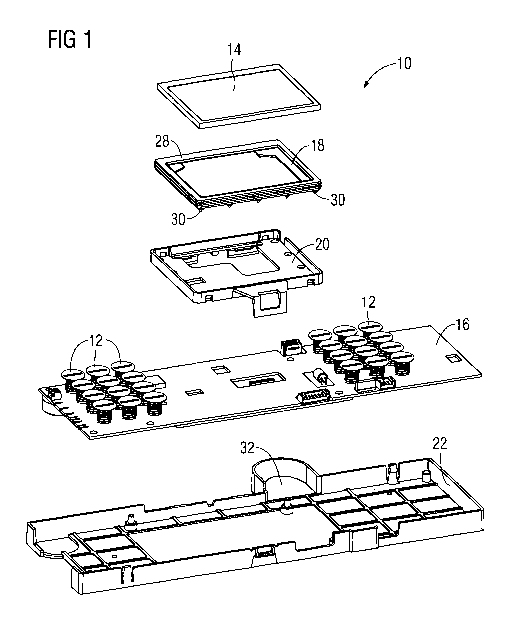
FIG 1 illustrates an exploded view of a preferred embodiment of-
a control unit according to the present invention, and
FIG 2 illustrates a sectional front view of a central portion
of the preferred embodiment of the control unit according
to the present invention.
FIG 1 illustrates an exploded view of a preferred embodiment of
a control unit 10 according to the present invention. The
control unit 10 comprises a display 14, a display frame 18, a
display carrier 20, a control panel 16 and an interface casing
22. For example, the display 14 may be TFT screen.
The display frame 18 includes a sealing lip 28 on its upper side
and a number of elastic knobs 30 at its lower side. On the
control panel 16 a plurality of control elements 12 is arranged.
The control panel 16 is formed as a board for electronic
elements.
4

CA 02769953 2012-02-02
WO 2011/023259 PCT/EP2010/004022
The display frame 18 is provided for receiving the display 14,
so that the display frame 18 encloses circumferentially the
display 14. The outer portions of both large-area sides of the
display 14 are also covered by the display frame 18.
The display carrier 20 is provided for receiving the display
frame 18 and the display 14, so that the display frame 18 with
the display 14 is embedded within said display carrier 20. The
sealing lip 28 of the display frame 18 is provided for sealing
the intermediate space between the display 14 and a viewing
window and/or a glass-ceramics panel.
The interface casing 22 is provided for receiving the control
panel 16. The interface casing 22 comprises a convexity 32 at
its side wall. The convexity 32 is provided for receiving a
ferrite element. The ferrite element can be used as a
suppression shielding of the electromagnetic field.
The display carrier 20 comprises a number of holes on its bottom
side, so that the elastic knobs 30 can penetrate through the
bottom side of the display carrier 20. The elastic knobs 30 are
provided for an elastic supporting of the display carrier 20
with the display frame 18 and the display 14 on the upper side
of the control panel 16. The display carrier 20 can be fixed on
the upper side of the control panel 16 within the interface
casing 22 by a snap-in mechanism. The elastic knobs 30 allow a
resilient bearing of the display carrier 20 with the display
frame 18 and the display 14.
In this example, the display frame 18 is a single-piece part and
is made of silicone. The silicone allows a sufficient resilience
of the sealing lip 28 and of the knobs 30.
5

CA 02769953 2012-02-02
WO 2011/023259 PCT/EP2010/004022
FIG 2 illustrates a sectional front view of the preferred
embodiment of a central portion of the control unit 10 according
to the present invention. The control unit 10 is a mounted state
and arranged between a glass-ceramics panel 24 and a support
panel 26.
The glass-ceramics panel 24 and the support panel 26 are aligned
horizontally and parallel to each other. The support panel 26 is
disposed at a distance below the glass-ceramics panel 24. For
example, the support panel 26 may be a spool carrier or a part
of a holding frame fixed at the glass-ceramics panel 24.
The control unit 10 includes the display 14, the display frame
18, the display carrier 20, the control panel 16 and the
interface casing 22. The display 14 is embedded within the
display frame 18. In turn, the display frame 18 with the display
14 is embedded within the display carrier 20.
The display 14, the display frame 18 and the display carrier 20
form a structural unit, which is moveably bedded between the
glass-ceramics panel 24 and the control panel 16. On the upper
side of said structural unit the sealing lip 28 is pressed
against the glass-ceramics panel 24. At the lower side of said
structural unit the elastic knobs 30 rest on the control panel
16. Thus, the structural unit is resiliently bedded between the
glass-ceramics panel 24 and the control panel 16.
The elastic knobs 30 allow a resilient bearing of the structural
unit including the display 14, the display frame 18 and the
display carrier 20. The elastic knobs 30 are able to compensate
manufacturing tolerances of the components of the control unit
10. The sealing lip 28 of the display frame 18 allows a dust-
free intermediate space between the display 14 and the glass-
ceramics panel 24.
6

CA 02769953 2012-02-02
WO 2011/023259 PCT/EP2010/004022
Although the above described control unit is provided for a
cooking with a glass-ceramics panel, in general, the inventive
cooking hob is suitable for an arbitrary cooking hob with at
least one viewing window.
Although illustrative embodiments of the present invention have
been described herein with reference to the accompanying
drawings, it is to be understood that the present invention is
not limited to those precise embodiments, and that various other
changes and modifications may be affected therein by one skilled
in the art without departing from the scope or spirit of the
invention. All such changes and modifications are intended to be
included within the scope of the invention as defined by the
appended claims.
7

CA 02769953 2012-02-02
WO 2011/023259 PCT/EP2010/004022
List of reference numerals
control unit
12 control element
5 14 display
16 control panel
18 display frame
display carrier
22 interface casing
10 24 glass-ceramics panel, viewing window
26 support panel
28 sealing lip
elastic knob
32 convexity
8

Representative Drawing
A single figure which represents the drawing illustrating the invention.
Administrative Status

2024-08-01:As part of the Next Generation Patents (NGP) transition, the Canadian Patents Database (CPD) now contains a more detailed Event History, which replicates the Event Log of our new back-office solution.

Please note that "Inactive:" events refers to events no longer in use in our new back-office solution.

For a clearer understanding of the status of the application/patent presented on this page, the site Disclaimer , as well as the definitions for Patent , Event History , Maintenance Fee  and Payment History  should be consulted.

Event History

Description Date
Time Limit for Reversal Expired 2014-07-08
Application Not Reinstated by Deadline 2014-07-08
Deemed Abandoned - Failure to Respond to Maintenance Fee Notice 2013-07-08
Inactive: Cover page published 2012-04-13
Inactive: Notice - National entry - No RFE 2012-03-14
Inactive: IPC assigned 2012-03-14
Application Received - PCT 2012-03-14
Inactive: First IPC assigned 2012-03-14
Inactive: IPC assigned 2012-03-14
National Entry Requirements Determined Compliant 2012-02-02
Application Published (Open to Public Inspection) 2011-03-03

Abandonment History

Abandonment Date Reason Reinstatement Date
2013-07-08

Maintenance Fee

The last payment was received on 2012-06-26

Note : If the full payment has not been received on or before the date indicated, a further fee may be required which may be one of the following

  • the reinstatement fee;
  • the late payment fee; or
  • additional fee to reverse deemed expiry.

Please refer to the CIPO Patent Fees web page to see all current fee amounts.

Fee History

Fee Type Anniversary Year Due Date Paid Date
Basic national fee - standard 2012-02-02
MF (application, 2nd anniv.) - standard 02 2012-07-06 2012-06-26
Owners on Record

Note: Records showing the ownership history in alphabetical order.

Current Owners on Record
ELECTROLUX HOME PRODUCTS CORPORATION N.V.
Past Owners on Record
ALWIN NEUKAMM
HARALD HOFFMANN
JUERGEN LEIKAM
MATHIAS HUNTSCHA
Past Owners that do not appear in the "Owners on Record" listing will appear in other documentation within the application.
Documents

To view selected files, please enter reCAPTCHA code :


To view images, click a link in the Document Description column. To download the documents, select one or more checkboxes in the first column and then click the "Download Selected in PDF format (Zip Archive)" or the "Download Selected as Single PDF" button.

List of published and non-published patent-specific documents on the CPD .

If you have any difficulty accessing content, you can call the Client Service Centre at 1-866-997-1936 or send them an e-mail at CIPO Client Service Centre.


Document
Description 
Date
(yyyy-mm-dd) 
Number of pages   Size of Image (KB) 
Description 2012-02-02 8 264
Representative drawing 2012-02-02 1 32
Claims 2012-02-02 3 83
Drawings 2012-02-02 2 62
Abstract 2012-02-02 2 81
Cover Page 2012-04-13 2 55
Reminder of maintenance fee due 2012-03-14 1 111
Notice of National Entry 2012-03-14 1 193
Courtesy - Abandonment Letter (Maintenance Fee) 2013-09-03 1 172
PCT 2012-02-02 10 365