Note: Descriptions are shown in the official language in which they were submitted.
CA 02770697 2012-02-09
WO 2011/025756 PCT/US2010/046421
METHOD AND APPARATUS FOR CONTINUOUS REMOVAL
OF SUBMICRON SIZED PARTICLES IN A CLOSED LOOP
LIQUID FLOW SYSTEM
This application claims priority under 35 U.S.C. 119(e) to U.S. Provisional
Application No. 61/236,810, filed on August 25, 2009.
Field of the Invention
[001] The present invention relates to a method and apparatus for continuous
removal of
submicron sized particles from blood or other liquids.
Background of the Invention
[002] In the prior art there are a range of particulate carriers intended for
the controlled
delivery of biologically active substances within the body. Their sizes range
from micron to
submicron, and their compositions range from organic (e.g. polymers, lipids,
surfactants,
proteins) to inorganic (calcium phosphate, silicate, CdSe, CdS, ZnSe, gold and
others). Each
of these particulate carriers are designed to carry a chemically or
biochemically reactive
substance, and either release it over time, or at a specific location, or
both.
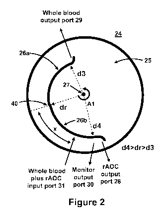
[003] The size of the individual particulate carriers and their load capacity
is controlled by
the amount of material used in the synthesis, the morphology by which the
components
assemble, and the specific composition of the components. The synthesized
particulate
carriers have the dual function of being able to solubilize or to be able to
bind to the
chemically or biochemically reactive substances intended for ultimate
delivery. The
underlying assumption is that the enclosed reactive substances will ultimately
be released so
that they can perform their intended functions. The particulate carriers
themselves usually do
not participate in the release function, except to the extent that they
regulate the timing or
location of release of the reactive substances they carry, and the carrier
components must
either decompose over time, or remain as non-active and non-toxic substances
that do not
cause any harm.
-1-
CA 02770697 2012-02-09
WO 2011/025756 PCT/US2010/046421
[004] In the field of medicine such particulate carriers have been used to
serve as artificial
oxygen carriers (AOC) in artificial blood products. Artificial blood is a
product made to act
as a substitute for red blood cells which transport oxygen and carbon dioxide
throughout the
body. However, the function of real blood is complicated, and the development
of artificial
blood has generally focussed on meeting only a specific function, gas exchange
- oxygen and
carbon dioxide.
[005] Whole blood serves many different functions that cannot be duplicated by
an AOC.
Artificial blood mixable with autologous blood can support patients during
surgery and
support transfusion services in emerging countries with limited healthcare,
blood donations
and storage facilities, or high risk of exposure to disease since screening
procedures are too
expensive. An AOC is a blood substitute, which is not dependent upon cross
matching and
blood-typing would mean no delay in blood availability, and could mean the
difference
between life and death of patients. In prior art medical applications the
residual materials
from particulate carriers are expected to be metabolized and/or excreted over
time. However,
the disposal of particulate carriers with natural metabolism of the patients
is extremely
difficult.
[006] Another motivation for developing improved AOC is that despite
significant advances
in donated blood screening there are still concerns over the limited shelf
life which is 42 days
at 2 - 6 C.
[007] In the era of modern science, several decades of extensive academic,
industry research
efforts, clinical trials, and spending multiple billions of dollars, has led
to two major classes
of AOCs, namely emulsified perfluorocarbons (PFC) and polymeric hemoglobins
(Hb).
While these two types of AOCs each have some advantages, none are yet approved
for
clinical use in the U.S.
[008] Chemically and biologically inert, emulsified, sterilized
perfluorocarbons (PFCs) are
stable in storage at low temperatures 2-5 C for over a year. Further, PFCs are
relatively
inexpensive to produce and can be made devoid of any biological materials
eliminating the
possibility of spreading an infectious disease via a blood transfusion.
Because they are not
soluble in water they must be combined with emulsifiers able to suspend tiny
droplets of PFC
in the blood. In vivo the perfluorocarbon is ultimately expelled via the lungs
after digestion
-2-
CA 02770697 2012-02-09
WO 2011/025756 PCT/US2010/046421
of the emulsifier by the macrophage/monocyte system. In addition, PFCs are
biologically
inert materials that can dissolve about fifty times more oxygen than blood
plasma but less
oxygen than red blood cells. For instance, a mixture consisting of 70% blood
and 30%
perfluorocarbon by volume can provide the needed 5 ml of oxygen per 100 ml of
blood if the
partial pressure of oxygen in the lungs can be increased to 120 mm Hg by
having the patient
breath air with an oxygen partial pressure of approximately 180 mm Hg.
[009] Perfluorocarbons (PFC) dissolve more oxygen than water, but still less
than normal
blood. To supply the needed amount of oxygen in circulation, patients may
require
supplemental oxygen. Highly hydrophobic PFC requires emulsifiers to stabilize
the droplet
in blood. These emulsifiers interact with proteins and emulsifiers found in
blood leading to
instability. As a result, large quantities of PFC in circulation in the blood
cannot be tolerated.
Small amounts of PFC escape from the blood into the lungs where it is
vaporized and
breathed out. Large amounts of PFC and emulsifier can have a negative effect
on lung
function.
[010] Crosslinked, polymerized or encapsulated hemoglobin (pHb) based
artificial oxygen
carriers (AOC) are late-comers compared with perfluorocarbon based AOCs
described in
previous paragraphs, and are attracting increasing attention because their
oxygen delivery
characteristics are similar to that of the red blood cells (hereinafter
referred to as RBC).
[011] Polymeric hemoglobins (pHb) bind 02 and C02, with a binding mechanism
much like
that of red blood cells (RBC), but even a small quantity of unpolymerized Hb
left in the
circulation can become very toxic. As an artificial oxygen carrier (AOC), a
large amount of
pHb needs to be injected into a person. Premature breakdown can increase the
risk of
toxicity, and such a large amount can overtax the body's natural removal
processes.
Polymerized Hb remains costly. Animal sources of Hb run the risk of
transferring, among
other things prion-based diseases. Recombinant Hb is a promising approach. It
requires high
quality separation and purification procedures, that add to the cost.
[012] While both polymeric hemoglobins (Hb) and perfluorocarbons (PFC) based
AOC
products deliver oxygen in significant quantities to cells and tissue, their
side effects, such as
nitric oxide related vasoconstriction, stroke, cardiac arrest, flu-like
symptoms and long term
chemical toxicity, have forced the termination of all the clinical trials in
the U.S. An all out
-3-
CA 02770697 2012-02-09
WO 2011/025756 PCT/US2010/046421
effort to reduce the toxicity of relatively large quantity of AOC injected
into a body by
metabolic decompositions has failed.
[013] In view of the many problems experienced with artificial blood products
and
particulate carriers intended for the controlled delivery of biologically
active substances
within the body, particulate artificial oxygen carriers (AOC) have been
developed that
minimize the above described problems in the prior art with non-particulate
AOCs. The
particulate AOCs are designed to be continually circulated in a closed loop
fluid circulation
system, are less subject to turbulent breakup, chemical decomposition, or
accumulation of
debris, and are capable of exchange of small ions and gases.
[014] However, while particulate AOC artificial oxygen carriers minimize the
problems of
earlier AOCs that are described above, they break down in time in the blood so
there is a
need in the art for a way to remove them from the body after they have served
their purpose
as an artificial oxygen carrier.
Summary of the Invention
[015] The need in the prior art described in the previous paragraph is
satisfied by the present
invention. To satisfy the above listed need in the prior art the present
invention is a
specialized centrifugal rotor that utilizes density gradient separation to
efficiently remove
particulate artificial oxygen carriers (hereinafter referred to as retrievable
AOCs or rAOC)
from blood or other biofluids. In addition, the rAOC is retrieved from a
patients system as
soon as its medical purpose is accomplished in order to alleviate the
physiological stress on
already compromised patients.
[016] With the present invention the particulate rAOCs can be retrieved at any
desired time
using continuous flow separation employing density-gradient centrifugation,
which may be
supplemented with magnetic fields, affinity filtration or other methods,
without suffering
damage, or inflicting damage on other materials that may already be present in
the flowing
fluid.
[017] Other applications for the present invention include removal and
concentration of
metastatic cancer cells from circulating blood, retrieval of low copy
mammalian, bacterial or
-4-
CA 02770697 2012-02-09
WO 2011/025756 PCT/US2010/046421
virus cells, and tissue and organ imaging. Depending on the application, the
specific design
requirement of these materials in terms of their size and composition may
vary, but common
to all of them are the properties summarized earlier, and the tailored ability
for continuous
retrieval from circulating fluids using the methods listed in the previous
paragraph.
[018] To remove the carrier particles from the blood one or more of the
following
continuous flow separation methods may be used: (a) centrifugation, (b)
magnetic fields, and
/ or (c) affinity filtration without suffering damage or inflicting damage on
other materials
that may already be present in the flowing fluid. It is contemplated that
particulate rAOCs be
removed from the bloodstream as soon as possible after they have performed
their function,
but prior to degradation of the particulate rAOCs, and subsequent development
of detrimental
side effects.
[019] To meet the criteria for retrievability of the above described
particulate rAOC
particles of the present invention from blood during their use, the
particulate material must be
submicron sized (50 nm - 700 nm) hollow particles filled with a high density
perfluorocarbon
(PFC) and / or a poly hemoglobin (pHb) liquid. The hollow particles have one
or two rigid
reinforcing shells. The exterior surface of these particulate shells are
coated with molecules
containing exposed functional groups (COOH, NH2, SH etc.) convenient for the
crosslinking
of either more than one particle, or proteins like antibodies, cell receptor
targets,
polyhemoglobin, hemoglobin etc.
[020] The single shell coated emulsion particles (rAOC) of the present
invention have a
higher density than other components of blood such as red blood cells, white
blood cells and
plasma. Accordingly, centrifugal forces may be utilized to separate the
particles from other
blood components, but density gradient is used rather than a sedimentation
velocity method
as in the prior art. In the prior art red blood cells are the furthest moving
particles in a
centrifugal field, but with the present invention the novel AOC is the
furthest moving
particles in the centrifugal field. With the AOC being the furthest moving
particles in a
centrifugal field they may be separated from all other blood components.
[021] rAOCs in the blood have a higher density than the blood and are
separated therefrom
by continuous flow density gradient centrifugation that utilizes the higher
density of the
-5-
CA 02770697 2012-02-09
WO 2011/025756 PCT/US2010/046421
rAOC particles to accomplish their separation. Affinity filtration may also be
used to
separate the rAOC nano or sub-nano size particles from the blood.
[022] In addition, paramagnetic materials may be added to the higher density
PFC in each
nanoparticle, and the magnetic susceptibility is used for the retrieval of the
polymerized
hemoglobin. The flowing liquid containing paramagnetic and diamagnetic
materials (the
natural blood component) must be exposed to a magnetic field during the
centrifugal
separation so that they will deviate in the direction of the flow of particles
with paramagnetic
materials away from the diamagnetic particles, thus making it possible to
separate and collect
both types of particles.
Description of the Drawing
[023] The invention will be better understood upon reading the following
Detailed
description in conjunction with the drawings in which:
[024] Figure 1 is a perspective view of the novel centrifuge that utilizes
density gradient
separation to efficiently remove particulate artificial oxygen carriers from
blood or other
biofluids;
[025] Figure 2 is a top view of the novel centrifuge that better shows the
novel rotor used in
the centrifuge;
[026] Figure 3 is a linear graphical representation of the novel rotor of the
centrifuge;
[027] Figure 4 is a block diagram of the circuits required for operation of
the novel
centrifuge that utilizes density gradient separation to efficiently remove
particulate artificial
oxygen carriers from blood or other biofluids;
[028] Figures 5A and 5B are transmission electron microscope images of
submicron sized
blood substitutes optimized for use with the described invention;
[029] Figure 6 is a cross sectional diagram showing how a single shelled rAOC
is
constructed; and
-6-
CA 02770697 2012-02-09
WO 2011/025756 PCT/US2010/046421
[030] Figure 7 is a cross sectional representation of a double shelled, dual
core oxygen
carrier (DCOC) that wraps a PFC emulsion core wrapped with a first shell on
the outside of
which is PolyHB that is wrapped with a second shell; and
Detailed Description
[031] Prior art coated particulate carriers intended for the controlled
delivery of biologically
active or medicinal substances within the body, or to serve as artificial
oxygen carriers
(AOC), break down in time in the blood so there is a need in the art for a way
to remove them
from the body after they have served their purpose. Hereinafter, only AOC are
specifically
mentioned but the teaching also applies to particulate carriers intended for
the controlled
delivery of biologically active or medicinal substances within the body.
[032] To meet the criteria for coated / particulate artificial oxygen carriers
that can be
temporarily substituted for blood, and for the retrievability of such coated
AOCs (hereinafter
referred to only as retrievable rAOC) from blood using the present invention,
the rAOCs
described herein are particulates having shells 12 (see Figures 5A and 5B)
that must be
submicron sized (50-1000 nm) hollow particles around a high density
perfluorocarbon (PFC)
emulsified nanoparticle. The reinforcing shell 12 is rigid and consists of a
combination of
lipids and inorganic materials like calcium phosphate, silicate, or
biocompatible organic
polymers such as, but not exclusively: polycaprolactone, polylactic acid,
polyglycolic acid,
polyethylene oxide, chitosan or chondroitin. The rAOCs nanoemulsion core
particles 11 are
denser than blood and the higher density is used to retrieve them from blood
using a special
centrifuge. Such shelled rAOCs are shown in and described very briefly with
reference to
Figures 5, 6, and 7.
[033] Simply, the novel means of the present invention for removing such rAOCs
from
blood comprises having a novel centrifuge rotor 24 that creates a density
gradient that
separates the rAOCS from the blood. In the prior art separation of mixed
components is
based sedimentation velocity. This is possible because the density of rAOC is
1.98 g/ml,
while the density of most of the blood components are only slightly over 1.0
g/ml. A mixture
of blood and rAOCs withdrawn from the body are input to a specific point in
the centrifuge
where the rotation of the centrifuge rotor 24 causes the blood to flow in one
direction and the
-7-
CA 02770697 2012-02-09
WO 2011/025756 PCT/US2010/046421
rAOCs to flow in the opposite direction, and they are both removed from the
centrifuge.
Before the separated rAOCs are retrieved a sample of the rAOC flow is removed
from the
centrifuge and input to a red blood cell (RBC) sensor which looks for any red
blood cells. If
any red blood cells are detected electronics of the system adjusts the speed
of the pumps
inputting and removing the RBC and rAOC from the centrifuge until no RBC are
detected in
the rAOCs to be removed from the centrifuge. In addition, the rotational speed
of the novel
rotor inside the centrifuge may also be adjusted. This is shown in and
described hereinafter
in greater detail with reference to Figure 4.
[034] Figure 1 is a perspective view of the novel centrifuge rotor 24 that
utilizes density
gradient separation to efficiently remove particulate artificial oxygen
carriers (rAOC) from
blood (RBC) or other biofluids. The case of the centrifuge and input and
output ports
therethrough are not shown in Figure 1 to make the drawing simpler so the
invention can be
better understood. Rotor 24 comprises a circular rotor base 25 that is mounted
on an axis 27
to a motor driven shaft (not shown). As shown in Figure 1 rotor base 25 is
rotated in a
counter clockwise direction for the rotor 24 configuration shown and described
herein. This
direction is important, based on the arrangement of rotor elements 26a and 26b
and their
position on rotor base 25, to create a density based gradient that separates
RBC (output at
port 29) from the rAOC (output at port 28) from a mixture of RBC and rAOC that
is input to
the centrifuge at port 31. Distances d3, d4 and dr are shown in all of Figures
1, 2 and 3 to
better understand how the Figures relate to each other. The thickness of rotor
26a,26b is 0.5
cm, the width is 2 cm, and the length is 15 cm, and the volume of the rotor
will be only 15 ml.
[035] Rotor 24 is made up of two curved elements 26a and 26b that are joined
together to
form a curved element 26a,26b that is oriented perpendicular to rotor base 25.
The curvature
of element 26b is slightly larger than the curvature of element 26a, and
curved composite
element 26a,26b is offset on rotor base 25 as may be seen in Figure 1, but is
better seen in the
top view of Figure 2. In Figure 1 the far left end and the far right end of
curved element
26a,26b curve outward a small amount to direct the flow of separated whole
blood to output
port 29 and to direct the separated / retrieved rAOC to output port 28 where
they exit the
centrifuge via their respective ports 28, 29 (not shown) through the case wall
(not shown) of
the centrifuge. The different curvatures of elements 26a and 26b and the
position of the
composite curved element 26a,26b on rotor base 25 create differing distances
d3, d4 and dr in
Figure 1 where d4>dr>d3. These distances are shown in Figures 1, 2 and 3 to
help
-8-
CA 02770697 2012-02-09
WO 2011/025756 PCT/US2010/046421
understand rotor 24 in all the Figures. As shown in Figures 1, 2 and 3 a
mixture of whole
blood (RBC) and AOCs is typically extracted from a body (not shown) and is
input to the
centrifuge at input port 31. As mentioned above the length of rotor 26a,26b is
15 cm but the
separation capacity per unit time could be increased by enlarging the width of
the rotor
26a,26b to greater than 2 cm. In an alternative embodiment of the invention
the curvatures of
rotor segments 26a and 26b may be the same.
[036] Figure 2 is a top view of the novel rotor 24 used in a centrifuge. As
previously
mentioned the different curvatures of rotor elements 26a and 26b and the
offset of composite
rotor element 26a,26b on rotor base 25 are best seen in Figure 2. More
particularly, rotor
26a,26b being belt shaped in the general shape of an ellipsoid with
overlapping ends. With
rotor 26a,26b being off centered on base 25 regions of high, medium and low
centrifugal
force are created depending on the distances from the axis of rotation 27. As
previously
mentioned the far left end and the far right end of curved composite element
26a,26b curve
outward a small amount to direct the flow of separated whole blood (RBC) to
output port 29
and to direct the separated / retrieved rAOC to output port 28 where they exit
the centrifuge
via their respective ports 28, 29 (not shown) through the case wall (not
shown) of the
centrifuge. The curvature of composite rotor element 26a,26b and its position
on rotor base
25 is best seen in this Figure. Input 31 where the composite mixture of RBC
and rAOC is
input to the centrifuge is offset from the junction of rotor elements 26a and
28b and is closer
to rAOC output port 28 by a circumferential distance "x" as shown. The reason
for this is
described further in this Detailed Description. The other input and output
ports have been
previously described with reference to Figure 1 so the description is not
repeated here. While
two rotor segments are shown in Figures 1 and 2, in alternative embodiments of
the invention
there may be more than two rotor segments.
[037] Figure 3 is a linear graphical representation of the novel rotor 24 of
the centrifuge.
This Figure shows how the distance between the face of composite rotor
elements 26a,26b
and the axis of rotation 27 of rotor 24 changes. Thus, the magnitude of
centrifugal force at
different regions of rotor 24 are depicted by the distance from the axis of
rotation 27, which is
stretched and shown as the dotted line at the top of Figure 2. The distances
d3, d4 and dr are
shown in all of Figures 1, 2 and 3 to better understand how the Figures relate
to each other.
The rate of change in distance is basically linear except where rotor element
26a meets rotor
element 26b. This is due to the fact the curvature of element 26a is different
than the
-9-
CA 02770697 2012-02-09
WO 2011/025756 PCT/US2010/046421
curvature of element 26b. In alternative embodiments of the invention the rate
of change in
distance may be uniform, and in another alternative embodiment the rate of
change may be
non-linear. Distances d3, d4 and dr between the face of rotor element 26a,26b
and axis 27
are shown to link Figure 3 with Figures 1 and 2. The input port 31 and output
ports 28, 29
and 30 and their relative position with respect to the linear depiction of
rotor 24 is shown.
[038] Whole blood including rAOCs obtained from a person who is connected in a
closed
loop system with a density gradient centrifuge is input to the centrifuge at
input port 31. The
whole blood is separated from the rAOC because the density of the rAOCs is
greater than the
density of the whole blood and any of its individual components. The whole
blood is output
at output port 29 and is returned to the person from whom the blood and rAOCs
was
withdrawn. The rAOCs are output at port 28 and stored for future use or
disposal. In
addition, at a particular location near where the rAOCs exit the centrifuge
via rAOC output
port 28, a small sample is removed from the density gradient centrifuge and
exits the
centrifuge at monitor output port 30. The sample is input to a red blood cell
sensor 32 of a
control circuit 38 to be checked for the presence of any remaining red blood
cells (RBC) with
the rAOCs about to exit the centrifuge. This is better shown in and described
with reference
to Figure 4. If any RBC are detected control circuit 38 adjusts the speed of
the blood and
rAOC pumps 36 and 37 that are part of circuit 38 to permit the centrifuge to
fully separate
any remaining RBC from the rAOC before the rAOC reaches monitor output port
30. This
feedback operation assures that only rAOCs exit rAOC output port 28.
[039] The centrifugal field generated in the density gradient centrifuge as
novel rotor 24
turns about its axis 27 (Figures 1 and 2) creates a density gradient field
that changes between
output ports 28 and 29. Depending on the shape of rotor elements 26a and 26b,
how they are
joined, and how they are positioned on rotor base 25 this density field may
change uniformly
or it may non-linearly. The result is that the lower density whole blood
fraction is separated
from the higher density rAOC fraction. In an alternative embodiment another
output port
may be added somewhere between output ports 28 and 29 to separate intermediate
density
fractions of blood. The separated whole blood and rAOC are withdrawn through
their
respective output ports as previously described. The whole blood collected may
be subjected
to further fractionation. For example, further fractionation may be used to
separate platelets
and white blood cells from the whole blood in a manner known in the art.
-10-
CA 02770697 2012-02-09
WO 2011/025756 PCT/US2010/046421
[040] More particularly as novel rotor 24 turns the density gradient field it
creates causes
the less dense, faster moving fractions of whole blood to move toward whole
blood output
port 29 and the more dense rAOC, however, migrate toward an area of the
chamber having
the greatest centrifugal force. By selecting the proper fluid in flow and out
flow rates through
the centrifuge, the physical dimensions of the rotor, and the speed of
rotation of the rotor in
the centrifuge, faster moving cells and slower moving cells may be separately
extracted from
the separation chamber and subsequently collected. In this manner, white blood
cells and
platelets may be separated and subsequently collected in separate collect
reservoirs.
Therefore, the combination of density centrifugation and centrifugal
elutriation provides
methods of separating blood components based on both density and sedimentation
velocity
properties.
[041] The basic design of the centrifuge rotor 26a,26b is a belt shaped
semicircular rotor
placed slightly off-centered from the axis of rotation as shown in Figures 1
and 2. Figure 1
is a three dimensional view of the rotor 26a,26b on the spinning rotor base
25, and Figure 2 is
a top view of rotor 26a,26b on the spinning rotor base 25. In Figure 3 the
rotor 26a,26b is
shown stretched out in a linear configuration to help show the location of the
rotor on rotor
base 25 with respect to axis of rotation 27.
[042] The semicircular rotor 26a,26b consists of two curved segments 26a and
26b, one
segment (26b) slightly more distanced from the axis of rotation 27 than the
other segment
(26a) and therefore experiencing higher centrifugal force, while the other
segment (26a) is
closer to the axis of rotation and therefore experiences less centrifugal
force than segment
(26b). A mixture of the blood and high-density particles (rAOC) enter the
outer wall of the
higher centrifugal force segment 26b as indicated as "Whole blood and rAOC
input 31) in
Figure 1, 2 and 3.
[043] With reference to Figure 3, as the centrifugation begins the rAOC of the
input mixture
31 remain at the wall of the furthest out rotor segment 26b, as it is the most
dense material
and moves towards the higher centrifugal field. This is to the right in Figure
3 and the output
is indicated as "Flow of rAOC Fr". In Figures 1 and 2 this is clockwise and
the output is
indicated as "rAOC output 28". All the blood components move toward the left
in Figure 3
toward closer rotor segment 26a because their densities are smaller and they
essentially float
-11-
CA 02770697 2012-02-09
WO 2011/025756 PCT/US2010/046421
on top of the rAOC. In Figures 1 and 2 this is counterclockwise and the blood
components
output is indicated as "Whole blood output 29".
[044] More particularly, as the blood and rAOC continue to be injected into
rotor 26a, 26b
at input 31 (shown in Figures 1 - 3), the blood components move towards the
lower
centrifugal field while the rAOC move to the higher centrifugal field. The
thickness of belt
shaped rotor 24 is only 5 mm. The separation of the rAOC and blood is carried
out very
quickly and form layers based are density of the particles. With separation
being
accomplished quickly it is possible maintain the rate of rAOC and blood inflow
sufficiently
fast to make the process "continuous-flow density separation". As mentioned
above the
rAOC leave the rotor at output 28 at the end of highest centrifugal force,
while the blood
components move leave the rotor at output 29 at the end of lowest centrifugal
force. The
semicircular rotor has a small offset, bend and protrusion near the junction
of segments 26a
and 26b to make the separation of rAOC from the blood complete. In Figures 1,
2 and 3 this
indicated by the number 40, but offset 40 is best seen in Figures 2 and 3.
More specifically, it
is possible to enhance the change of centrifugal force by creating a
protrusion at the site
where distinctive separation of two layers is made, since their sedimentation
coefficients are
predominantly a function of (1 - p/8), the particulates will be positioned
close to the outer
wall of the rotor when the density equilibrium is established.
[045] Near at the exit port 28 of the rAOC, there is a monitor output port 30,
from which
small samples are taken of the rAOC flowing toward its output 28 to test the
purity of the
rAOC. The testing of the rAOC is shown in and described with reference to
Figure 4. The
purity of the rAOC might change slowly over time during centrifugal retrieval
of the rAOC
so the relative flow rates of pumps 36 and 37 must be adjusted to maintain the
purity of the
rAOC output at its port 28. The addition of all out-flows of the rAOC and
blood should equal
to the inflow of the blood and rAOC, i.e. Fbr = Fr + Fm + Fb.
[046] In Figure 4 is a block diagram of circuits required for successful
operation of the
novel centrifuge that utilizes density gradient separation to efficiently
remove particulate
artificial oxygen carriers (rAOC) from blood or other biofluids. The circuits
first comprise a
red blood cell (RBC) sensor 32 that receives the previously mentioned sample
output from
the centrifuge at monitor output 30. The concentration of any contaminating
low density
RBC in the sample taken at output 30 is detected spectrophotometrically. The
output from
-12-
CA 02770697 2012-02-09
WO 2011/025756 PCT/US2010/046421
RBC sensor 32 is amplified by amplifier 33 and is then input to two logic
circuits 34 and 35.
Circuits 34 and 35 are programmed to respond to any output from sensor 32 to
provide output
signals that will change the operation of pumps 36 and 37 which thereby can
change either or
both of the flow rate of lower density blood flowing out at blood output 29
and higher density
rAOC flowing out at blood output 28. In addition, there can be a programmed
logic circuit
38 that responds to the output from sensor 32 and, in cooperation with logic
circuits 34 and
35, provides and output at 39 to the motor that rotates rotor 24 to change its
rotational speed.
[047] Figures 5 A&B shows typical electron microscope pictures of the shelled
rAOC
particles 11. The shells 12 of these novel rAOC particles 11 are coated with
molecules
containing exposed functional groups (COOH, NH2, SH etc.) convenient for the
crosslinking
of either more than one particle, or proteins like antibodies, cell receptor
targets,
polyhemoglobin, hemoglobin etc. Outer ring or shell 12 is a gas permeant
calcium phosphate
or polymer coating, while the interior is an oxygen carrying center containing
a hemoglobin
(HB) 13 nanoparticle and/or a perfluorocarbon (PFC) 14 nanoparticle.
[048] Very briefly, single shell rAOCs 11 are made as follows. Nanoemulsion
particles 13
are made from a mixture of perfluorooctylbromide (PFOB) 21, 1,2-dioleoyl-sn-
glycero-
phosphate (DOPA)22 and water, preferably by a stirring process, but other
methods known in
the art may be utilized.
The outer surface of the perfluorooctylbromide (PFOB) nanoparticles 11 has a
surface of 1,2-
dioleoyl-sn-glycero-phosphate (DOPA) 22 surrounding a nanomulsion particle 21.
The
uncoated (non-mineralized) nanoemulsion particles 13 have a negatively charged
surface of
P03 created by using phosphatidic acid to stabilize the nanoemulsion
particles. Since the
synthesis of nanoemulsion particles takes place under basic conditions, the
surface charge
density of the nanoemulsion is quite high with zeta potentials nearing -50 mV.
[049] To coat the negatively charged nanoemulsions particles 13 they may be
mixed with
2:00 l of 0.1 M phosphoric acid solution. Next, a CaC12 solution is added
followed by a
CEPA solution to coat the nanoemulsion particles and arrest further calcium
phosphate
deposition. In this process positively charged calcium ions from the
phosphoric acid are
attracted to the negatively charged P03 on the surface of the nanoemulsion
particles 13
(DOPA) as shown in Figure 6. The accumulation of calcium ions at the periphery
of the
nanoemulsion particles increases the local concentration past the stability
point for calcium
-13-
CA 02770697 2012-02-09
WO 2011/025756 PCT/US2010/046421
phosphate precipitation resulting in precipitation of calcium phosphate onto
the nanoemulsion
particles to form a shell. The finished shelled, particles function well as
oxygen carriers in
blood.
[050] A second shell and second oxygen carrier may be added as shown in Figure
7. First,
Polylysine/Hb is deposited layer by layer onto the negatively charged
carboxylated surface of
the first shell made as described above. Then a mixture of perfluorocarbon
(PFC) and
Polyhemoglobin (Po1yHB) is coated over the first shell and the same previously
described
method is used to place a second shell over the PFC and PolyHB. The second
shell makes
the rAOC particles tougher and even better able to withstand being retrieved
from circulating
blood using the continuous flow density gradient separation technique
described above. The
finished shelled, particles function well as oxygen carriers in blood.
[051] The novel density gradient separation technique taught and claimed
herein maybe
used to separate other mixtures of substances having different densities. It
may be used to
separate and remove metastatic cancer cells from circulating blood. It may
also be used for
retrieval of low copy mammalian, bacterial or virus cells from blood. It may
also be used to
remove materials added to blood to enhance tissue and organ imaging. Depending
on the
application, the specific design requirement of these materials in terms of
their size and
composition may vary, but common to all of them are the properties summarized
earlier, and
the tailored ability for continuous retrieval from circulating fluids.
[052] While what has been described herein is the preferred embodiment of the
invention it
will be understood by those skilled in the art that numerous changes may be
made without
departing from the spirit and scope of the invention.
-14-