Note: Descriptions are shown in the official language in which they were submitted.
CA 02770735 2016-12-19
MASKED INTRAOCULAR IMPLANTS AND LENSES
BACKGROUND
Field
[0002] This application relates generally to the field of intraocular
devices.
More particularly, this application is directed to intraocular implants and
lenses (IOLs),
with an aperture to increase depth of focus (e.g. "masked" intraocular lenses)
and methods
of making.
Description of the Related Art
[0003] The human eye functions to provide vision by transmitting and
focusing
light through a clear outer portion called the cornea, and further refining
the focus of the
image by way of a crystalline lens onto a retina. The quality of the focused
image depends
on many factors including the size and shape of the eye, and the transparency
of the cornea
and the lens.
[0004] The optical power of the eye is determined by the optical power
of the
cornea and the crystalline lens. In a normal, healthy eye, sharp images of
distant objects
are formed on the retina (emmetropia). In many eyes, images of distant objects
are either
formed in front of the retina because the eye is abnormally long or the cornea
is abnormally
steep (myopia), or formed in back of the retina because the eye is abnormally
short or the
cornea is abnormally flat (hyperopia). The cornea also may be asymmetric or
toric,
resulting in an uncompensated cylindrical refractive error referred to as
corneal
astigmatism.
[0005] A normally functioning human eye is capable of selectively
focusing on
either near or far obj ects through a process known as accommodation.
Accommodation is
achieved by inducing deformation in a lens located inside the eye, which is
referred to as
the crystalline lens. Such deformation is induced by muscles called ciliary
muscles. In
most
-1-
CA 02770735 2012-02-09
WO 2011/020078 PCT/US2010/045548
individuals, the ability to accommodate diminishes with age and these
individuals cannot see
up close without vision correction. If far vision also is deficient, such
individuals are usually
prescribed bifocal lenses.
SUMMARY OF THE INVENTION
100061 This application is directed to intraocular implants for
improving the
vision of a patient, such as by increasing the depth of focus of an eye of a
patient. The
intraocular implants can include a mask having an annular portion with a
relatively low
visible light transmission surrounding a relatively high transmission central
portion such as a
clear lens or aperture. This construct is adapted to provide an annular mask
with a small
aperture for light to pass through to the retina to increase depth of focus,
sometimes referred
to herein as pin-hole imaging or pin-hole vision correction. The intraocular
implant may
have an optical power for refractive correction. For example, the mask can be
embodied in
or combined with intraocular lenses (IOLs). The intraocular implant may be
implanted in any
location along the optical pathway in the eye, e.g., as an implant in the
anterior or posterior
chamber.
100071 IOLs have been developed that provide a safe and effective
surgical
solution for cataracts. These lenses are surgically implanted after removal of
a cataractous
natural lens of the eye, restoring clarity and providing a replacement for the
optical power
that was removed. In a successful IOL implantation, the patient is typically
emmetropic
afterwards, meaning that their eye is focused for distance. However,
conventional IOLs
cannot accommodate to focus at different distances, so the patient typically
needs additional
correction (e.g.. reading glasses) to see near objects clearly. Intraocular
implants disclosed
herein provide an improvement over presently available IOLs by incorporating a
-mask- in
the form of an aperture that improves depth of focus.
100081 In certain embodiments, an intraocular device includes a lens
body. The
lens body includes an anterior and posterior surface. The posterior surface
includes a first
convex portion. a second concave portion and a third convex portion. The
second concave
portion is adjacent the first convex portion and the third convex portion. The
third convex
portion is annular and surrounds the second concave portion. and the second
concave portion
-2-
CA 02770735 2012-02-09
WO 2011/020078
PCT/US2010/045548
is annular and surrounds the first convex portion. An optical power between
the first convex
portion and the anterior surface is positive and an optical power between the
third convex
portion and the anterior surface is positive. The lens body further includes a
mask positioned
between the second concave portion and the anterior surface.
100091 In certain embodiments, a lens body of an intraocular device
includes a
first surface and a second surface. A first portion of the first surface is
convex, a second
portion of the first surface is concave, and a third portion of the first
surface is convex. The
second portion is adjacent the first portion and the third portion. The lens
body further
includes a mask positioned to block a substantial portion of optical
aberrations that would be
created by the light passing through the second portion of the first surface.
100101 In certain embodiments, an intraocular device includes a lens
body with a
positive optical power. The lens body includes an outer region and a recessed
central region.
At least a portion of the recessed central region includes a thickness less
than at least a
portion of the outer region. The lens body further includes a mask coupled
with a curved
transition between the outer region the recessed central region.
100111 In certain embodiments, a method of making an intraocular device
includes providing a lens body with a first surface and a second surface. The
method further
includes forming a convex surface on a first portion of the first surface, a
concave surface on
a second portion of the first surface and a convex surface on a third portion
of the first
surface. The second portion is adjacent the first portion and the third
portion. The method
also includes attaching a mask to the lens body that is positioned to block a
substantial
portion of the light passing through the second portion of the first surface.
100121 In certain embodiments. a method of making an intraocular device
includes forming a rod with an optically transparent inner region along a
length of the rod, an
optically transparent outer region along the length of the rod and a
substantially optically non-
transparent region along the length of the rod between the inner region and
the outer region.
The substantially non-transparent region can be a middle region. as discussed
below. The
method also can include sectioning the rod along a plane substantially
perpendicular to an
axis parallel to the length of the rod to form a lens body with a first
surface and a second
surface. The method also can include forming a convex surface on a first
portion of the first
-3-
CA 02770735 2012-02-09
WO 2011/020078 PCT/US2010/045548
surface. The first portion can correspond to the inner region of the sectioned
rod. The
method can include forming a concave surface on a second portion of the first
surface. The
second portion can correspond to the non-transparent region. The method can
include
forming a convex surface on a third portion of the first surface. The third
portion can
correspond to the outer region. The second portion is adjacent the first
portion and the third
portion. In some embodiments, the non-transparent region is positioned such
that, in use, the
non-transparent region blocks a substantial portion of the light passing
through the second
portion of the first surface.
100131 In certain embodiments, a method of making an intraocular device
includes forming a lens body around a mask. The mask includes an aperture and
an annular
region, and the lens body comprising a first surface and a second surface. The
method further
includes forming a convex surface on a first portion of the first surface, a
concave surface on
a second portion of the first surface and a convex surface on a third portion
of the first
surface. The second portion is adjacent the first portion and the third
portion. Forming the
lens body around the mask includes locating the mask within the lens body such
that, in use,
the mask blocks a substantial portion of the light passing through the second
portion of the
first surface.
10014] In certain embodiments, an intraocular implant includes an
implant body.
The implant body can include a pin-hole aperture in the implant body, and a
mask
substantially around the pin-hole aperture. The implant body can further
include an outer
hole region substantially outside an outer perimeter of the mask. The outer
hole region can
include at least one outer hole and at least one connection portion. An outer
region of the
implant body can be attached to the mask by the at least one connection
portion.
100151 In some embodiments, an intraocular device includes a lens body
comprising a surface with a transition zone, the transition zone configured to
reduce a
thickness of the lens body along an optical axis of the lens body, and a mask
configured to
block a substantial portion of optical aberrations that would be created by
light passing
through the transition zone.
10016] In further embodiments, an intraocular device includes a lens
body
comprising a first surface and a second surface. The first surface comprises a
first portion, a
-4-
CA 02770735 2012-02-09
WO 2011/020078 PCT/US2010/045548
second portion and a third portion. An optic axis of the lens body passes
through the first
portion, and the second portion is between the first portion and the third
portion. The
intraocular device can also include a mask positioned between the second
surface and the
second portion of the first surface. A distance from the first portion
neighboring the second
portion to a plane perpendicular to the optic axis and tangent to the second
surface can
comprise a first distance, and a distance from the third portion neighboring
the second
portion to the plane perpendicular to the optic axis and tangent to the second
surface can
comprise a second distance greater than the first distance.
[0017] In other embodiments, a method for improving the vision of a
patient
includes providing an intraocular device comprising a lens body comprising a
surface with a
transition zone. The transition zone can be configured to reduce a thickness
of the lens body
along an optic axis of the lens body, and the intraocular device can further
include a mask
configured to block a substantial portion of optical aberrations that would be
created by light
passing through the transition zone. The method can further include inserting
the intraocular
device into an intraocular space of an eye.
[0018] In certain embodiments, an intraocular implant includes an
implant body
comprising an outer surface that includes a posterior surface and an anterior
surface, an
opaque mask positioned between the posterior surface and the anterior surface
of the implant
body. The mask comprising an aperture. The intraocular implant can further
include a
support member coupled to the mask and extending from the mask to the outer
surface of the
implant body. The support member can extend from the mask to the posterior
surface of the
implant body. A first portion of the support member neighboring the mask can
have a first
cross-sectional area parallel the mask and a second portion of the support
member
neighboring the posterior surface can have a second cross-sectional area
parallel the mask
that is less than the first cross-sectional area. The support member may be
configured to be
removable from the intraocular implant. The support member may include a
plurality of
holes characterized in that at least one of the hole size, shape. orientation,
and spacing of the
plurality of holes is varied to reduce the tendency of the holes to produce
visible diffraction
patterns.
-5-
CA 02770735 2012-02-09
WO 2011/020078 PCT/US2010/045548
[0019] In certain embodiments, a method of making an intraocular
implant
includes providing an opaque mask comprising an aperture and at least one
support member
coupled to the mask, positioning the mask within a mold chamber such that the
at least one
support member is coupled to the mold chamber so that the mask resists
movement, and
flowing a lens material into the mold chamber so that at least a portion of
the mask is encased
within the lens material. The method may further include removing at least a
portion of the
at least one support member after injecting the lens material.
[0020] In other embodiments, a method of making an intraocular implant
includes
coupling an opaque mask comprising an aperture to a surface of a mold chamber,
and flowing
a lens material into the mold chamber to foul' an optic coupled to the mask.
[0021] In further embodiments, a method of making an intraocular
implant
includes removing a portion of a surface of an optic to form an annular cavity
around an
aperture region, at least partially filling the cavity with an opaque
material, removing at least
some of the aperture region and a central region of the optic to reduce a
thickness of the
aperture region of the optic. At least some of the opaque material may remain
on the surface
of the optic to form an opaque mask.
[0022] In another embodiment, a method of making an intraocular implant
includes providing an optic with an annular cavity around an aperture region,
at least partially
filling the cavity with an opaque material, removing at least some of the
aperture region and a
central region of the optic to reduce a thickness of the aperture region of
the optic. At least
some of the opaque material can remain on the surface of the optic to form an
opaque mask.
100231 In even further embodiments, a method of making an intraocular
implant
includes positioning an opaque mask with an aperture within a mold cavity such
that the
mask is not in physical contact with the mold cavity, and injecting an implant
body material
into the mold cavity to form an implant body around the mask. For example, the
mask can be
positioned with magnetic fields or with wires extending from the mask to a
frame outside of
the mold cavity.
100241 In certain embodiments, a intraocular implant includes an
implant body
comprising a body material and a mask with an aperture positioned within the
implant body.
The mask can include a plurality of holes that extend between a posterior
surface and an
-6-
CA 02770735 2012-02-09
WO 2011/020078 PCT/US2010/045548
anterior surface of the mask. The body material can extend through the
plurality of holes of
the mask, and the plurality of holes can be characterized in that at least one
of the hole size,
shape, orientation, and spacing of the plurality of holes is varied to reduce
the tendency of the
holes to produce visible diffraction patterns. The plurality of holes may be
positioned at
irregular locations. A first plurality of the holes may include first hole
size, shape or spacing
and at least another plurality of holes may include a second hole size, shape,
or spacing
different from the first holes size, shape, or spacing. A first plurality of
the holes may include
first hole size, a second plurality of the holes may include a second hole
size different from
the third hole size, and a third plurality of holes may include a third hole
size different from
the first holes size and the second hole size.
100251 In certain embodiments, an intraocular implant includes an
implant body
configured to be implanted into a sulcus region of an eye of a patient. The
implant body can
include an aperture that is at least partially surrounded by an opaque region
forming a mask
and an outer hole region substantially outside an outer perimeter of the mask.
The outer hole
region can include at least one outer hole and at least one connection
portion, and the outer
hole region can have an incident visible light transmission of at least 90%.
The implant body
may also include an outer region attached to the mask by the at least one
connection portion.
10026J In other embodiments, a method of making an intraocular implant
includes
providing an implant body configured to be implanted into a sulcus region of
an eye of a
patient, forming an aperture in the implant body by removing a portion of the
implant body,
and forming at least one opening between the outer edge of the structure and a
opaque mask
region that neighbors the aperture.
BRIEF DESCRIPTION OF THE DRAWINGS
100271 Figure IA illustrates a front plan view of an embodiment of an
intraocular
lens with a recessed central region on the posterior surface as described
herein.
100281 Figure 1B illustrates a cross-sectional view of the intraocular
lens of
Figure IA.
100291 Figure 2A illustrates a front plan view of an embodiment of an
intraocular
lens with a recessed central region on the anterior surface as described
herein.
-7-
CA 02770735 2012-02-09
WO 2011/020078 PCT/US2010/045548
10030] Figure 2B illustrates a cross-sectional view of the intraocular
lens of
Figure 2A.
100311 Figure 3A illustrates a front plan view of an embodiment of an
intraocular
lens with a recessed central region on the posterior surface and anterior
surface as described
herein.
10032] Figure 3B illustrates a cross-sectional view of the intraocular
lens of
Figure 3A.
[0033] Figure 4A illustrates a front plan view of an embodiment of an
intraocular
lens with two transition zones and two masks as described herein.
[0034] Figure 4B illustrates a cross-sectional view of the intraocular
lens of
Figure 4A.
[0035] Figure 5A illustrates a front plan view of an embodiment of an
intraocular
lens with two transition zones and a single mask as described herein.
100361 Figure 5B illustrates a cross-sectional view of the intraocular
lens of
Figure 5A.
[0037] Figure 6A illustrates a front plan view of an embodiment of an
intraocular
lens with a concave posterior surface and a positive optical power as
described herein.
100381 Figure 6B illustrates a cross-sectional view of the intraocular
lens of
Figure 6A.
[0039] Figure 7A illustrates a front plan view of an embodiment of an
intraocular
lens with a concave posterior surface and a negative optical power as
described herein.
[0040] Figure 7B illustrates a cross-sectional view of the intraocular
lens of
Figure 7A.
10041] Figure 8 is a cross-sectional schematic representation of light
passing
through the intraocular lens of Figure 2B.
[0042] Figure 9 is a schematic representation of light from a far
object transmitted
through an eye having an embodiment of an intraocular lens that is in the
capsular bag.
100431 Figure l OA illustrates a top view of a conventional
intraocular lens.
100441 Figure 10B illustrates a cross-sectional view of the
conventional
intraocular lens of Figure 10A.
-8-
CA 02770735 2012-02-09
WO 2011/020078 PCT/US2010/045548
[0045] Figure 11A is a perspective view of one embodiment of a mask.
[0046] Figure 11B is a perspective view of an embodiment of a
substantially flat
mask.
[0047] Figure 12 is a side view of an embodiment of a mask having
varying
thickness.
10048] Figure 13 is a side view of another embodiment of a mask having
varying
thickness.
100491 Figure 14 is a side view of an embodiment of a mask with a
material to
provide opacity to the mask.
[0050] Figure 15 is an enlarged, diagrammatic view of an embodiment of
a mask
that includes particulate structure adapted for selectively controlling light
transmission
through the mask in a low light environment.
[0051] Figure 16 is a view of the mask of Figure 15 in a bright light
environment.
100521 Figure 17 is another embodiment of a mask that includes
connectors for
securing the mask within the eye.
[0053] Figure 18A is a top view of another embodiment of a mask
configured to
increase depth of focus.
[0054] Figure 18B is an enlarged view of a portion of the view of
Figure 18A.
100551 Figure 19 is a cross-sectional view of the mask of Figure 18B
taken along
the section plane 19-19.
100561 Figure 20A is a graphical representation of one arrangement of
holes of a
plurality of holes that may be formed on the mask of Figure 18A.
[0057] Figure 20B is a graphical representation of another arrangement
of holes
of a plurality of holes that may be formed on the mask of Figure 18A.
100581 Figure 20C is a graphical representation of another arrangement
of holes
of a plurality of holes that may be formed on the mask of Figure I 8A.
[0059] Figure 21A is an enlarged view similar to that of Figure 18A
showing a
variation of a mask having non-uniform size.
[00601 Figure 21B is an enlarged view similar to that of Figure 18A
showing a
variation of a mask having a non-unifol in facet orientation.
-9-
CA 02770735 2012-02-09
WO 2011/020078 PCT/US2010/045548
100611 Figure 22 is a top view of another embodiment of a mask having
a hole
region and a peripheral region.
[0062] Figure 23 is a flow chart illustrating one method for making a
masked
intraocular implant from a mask comprising a highly fluorinated polymer and an
pacification agent.
[0063] Figure 24A is a top plan view of an embodiment of a mask
configured to
increase depth of focus as described herein.
[0064] Figure 24B is a front plan view of an embodiment of a mask
configured to
increase depth of focus as described herein.
[0065] Figure 24C is a front plan view of an embodiment of a mask
configured to
increase depth of focus as described herein.
100661 Figure 24D is a front plan view of an embodiment of a mask
configured to
increase depth of focus as described herein.
[0067] Figure 25A is a cross-sectional view of an embodiment of an
intraocular
implant with a mask coupled to the anterior surface of a transition zone as
described herein.
100681 Figure 25B is a cross-sectional view of an embodiment of an
intraocular
implant with a mask coupled to the posterior surface as described herein.
[0069] Figure 25C is a cross-sectional view of an embodiment of an
intraocular
implant with a mask embedded within the implant body about midway between the
posterior
and anterior surfaces as described herein.
[0070] Figure 25D is a cross-sectional view of an embodiment of an
intraocular
implant with a mask embedded within the implant body which is closer to the
anterior
surface than the posterior surface as described herein.
[0071] Figure 25E is a cross-sectional view of an embodiment of an
intraocular
implant with a mask embedded within the implant body which is closer to the
posterior
surface than the anterior surface as described herein.
100721 Figure 25F is a cross-sectional view of an embodiment of an
intraocular
implant with a mask embedded within the implant body and within close
proximity of the
anterior surface of a transition zone as described herein.
-10-
CA 02770735 2012-02-09
WO 2011/020078 PCT/US2010/045548
100731 Figure 25G is a cross-sectional view of an embodiment of an
intraocular
implant with a mask that extends between the anterior and posterior surfaces
as described
herein.
100741 Figure 26A is a front plan view of an embodiment of an
intraocular
implant with support members extending from the mask to a peripheral surface
of the implant
body as described herein.
100751 Figure 26B is a cross-sectional view of an embodiment of an
intraocular
implant with support members extending from the mask to the posterior surface
of the
implant body as described herein.
100761 Figure 26C is a cross-sectional view of an embodiment of an
intraocular
implant with a mask integrated with the support members as described herein.
100771 Figure 27A is a cross-sectional view of an embodiment of an
intraocular
implant with tabs extending from the mask to the posterior surface of the
implant body as
described herein.
100781 Figure 27B is a cross-sectional view of the intraocular implant
of Figure
27A wherein a portion of the tabs have been removed.
100791 Figure 28A is a front plan view of an embodiment of an
intraocular
implant with a support member as described herein.
100801 Figure 28B is a cross-sectional view of the intraocular implant
of Figure
28A.
100811 Figure 29A is a front plan view of an embodiment of an
intraocular
implant with a different optical power than the intraocular implant of Figure
27A.
100821 Figure 29B is a cross-sectional view of the intraocular implant
of Figure
29A.
100831 Figure 30A is a front plan view of an embodiment of an
intraocular lens
with a mask that extends radially beyond the outer periphery of the transition
zone as
described herein.
100841 Figure 30B is a cross-sectional view of the intraocular implant
of Figure
30A.
-11-
CA 02770735 2012-02-09
WO 2011/020078 PCT/US2010/045548
100851 Figure 31A is a front plan view of another embodiment of an
intraocular
implant with a support member as described herein.
[0086] Figure 31B is a cross-sectional view of the intraocular implant
of Figure
31 A.
100871 Figure 32A is a front plan view of another embodiment of an
intraocular
implant with a mask that extends radially beyond the outer periphery of the
transition zone as
described herein.
100881 Figure 32B is a cross-sectional view of the intraocular implant
of Figure
32A.
100891 Figure 33A is a front plan view of a further embodiment of an
intraocular
implant with a support member as described herein.
[0090] Figure 33B is a cross-sectional view of the intraocular implant
of Figure
33A.
100911 Figure 34A is a front plan view of a further embodiment of an
intraocular
implant with a mask that extends radially beyond the outer periphery of the
transition zone as
described herein.
[0092] Figure 34B is a cross-sectional view of the intraocular implant
of Figure
34A.
100931 Figure 35A is a front plan view of an embodiment of an
intraocular
implant with a support member coupled with a haptic as described herein.
100941 Figure 35B is a cross-sectional view of the intraocular implant
of Figure
35A.
[0095] Figure 36A is a front plan view of another embodiment of an
intraocular
implant with a support member coupled with a haptic as described herein.
[0096] Figure 36B is a cross-sectional view of the intraocular implant
of Figure
36A.
[0097] Figure 37A is a cross-section view of an intraocular implant.
100981 Figure 37B is a cross-section view of the intraocular implant of
Figure
37A with a cavity formed into the implant body.
-12-
CA 02770735 2012-02-09
WO 2011/020078 PCT/US2010/045548
100991 Figure 37C is a cross-section view of the intraocular implant of
Figure
37B with the cavity at least partially filled with an opaque material.
101001 Figure 37D is a cross-sectional view of the intraocular implant
of Figure
37C with a portion of the opaque material and central region removed.
101011 Figure 38A is a cross-section view of an intraocular implant.
101021 Figure 38B is a cross-section view of the intraocular implant of
Figure
38A with a cavity formed into the implant body.
101031 Figure 38C is a cross-section view of the intraocular implant of
Figure
38B with mask positioned within the cavity.
101041 Figure 38D is a cross-section view of the intraocular implant of
Figure
38C with the cavity at least partially filled with an implant body material.
101051 Figure 38E is a cross-section view of the intraocular implant of
Figure
38D with a portion of the implant body removed.
[0106] Figure 39A is a cross-section view of an intraocular implant.
101071 Figure 39B is a cross-section view of the intraocular implant of
Figure
38A with a cavity formed into the implant body.
10108] Figure 39C is a cross-section view of the intraocular implant of
Figure
39B with the cavity at least partially filled with an opaque material.
101091 Figure 39D is a cross-sectional view of the intraocular implant
of Figure
39C with a portion of the opaque material and central region removed.
101101 Figure 40 is a schematic of an embodiment of a mask positioning
system
for positioning a mask within a mold cavity as described herein.
101111 Figure 41 is an illustration of an embodiment of a mask
positioning
apparatus that includes wires coupled to a mask and a frame as described
herein.
101121 Figure 42 is a side view of an embodiment of a mask levitated
with a
magnetic field as described herein.
(0113] Figure 43A is a top view of an embodiment of a mask levitated
above of
magnetic fields as described herein.
101141 Figure 43B is a top view of another embodiment of a mask
levitated above
of magnetic fields as described herein.
-13-
CA 02770735 2012-02-09
WO 2011/020078 PCT/US2010/045548
101151 Figure 44 is a schematic of an embodiment of using
electrostatic levitation
to position a mask as described herein.
101161 Figure 45 is a top view of an embodiment of a bistable display
that is
capable of forming a mask as described herein.
101171 Figure 46 is a top perspective view of an embodiment of a
masked
intraocular implant configured to increase depth of focus described herein.
[0118] Figure 47 is a top plan view of the intraocular implant of
Figure 46.
[0119] Figure 48A is a side elevational view of an embodiment of an
intraocular
implant with a mask through the intraocular implant of Figure 46.
[0120] Figure 48B is a side elevational view of an embodiment of an
intraocular
implant with a mask on the posterior surface of the intraocular implant.
[0121] Figure 48C is a side elevational view of an embodiment of an
intraocular
implant with a mask on the anterior surface of the intraocular implant.
10122] Figure 48D is a side elevational view of an embodiment of an
intraocular
implant with a mask positioned midway between the posterior and anterior
surfaces of the
intraocular implant.
101231 Figure 48E is a side elevational view of an embodiment of an
intraocular
implant with a mask positioned between the posterior surface and a midway
position between
the posterior and anterior surfaces of the intraocular implant.
[0124] Figure 48F is a side elevational view of an embodiment of an
intraocular
implant with a mask positioned between the anterior surface and a midway
position between
the posterior and anterior surfaces of the intraocular implant.
[0125] Figure 49A is a top perspective view of an embodiment of an
intraocular
implant with five outer holes described herein.
101261 Figure 49B is a top plan view of the intraocular implant of
Figure 56A.
101271 Figure 49C is a side elevational view of the intraocular
implant of Figure
56A.
[0128] Figure 50A is a top perspective view of an embodiment of an
intraocular
implant with a different haptic than the intraocular implant of Figure 56A
described herein.
101291 Figure 50B is a top plan view of the intraocular implant of
Figure 57A.
-14-
CA 02770735 2012-02-09
WO 2011/020078 PCT/US2010/045548
101301 Figure 50C is a side elevational view of the intraocular implant
of Figure
57A.
101311 Figure 51A is a top plan view of an embodiment of an intraocular
implant
with a single outer hole described herein.
[0132] Figure 51B is a top plan view of an embodiment of an intraocular
implant
with two outer holes described herein.
[0133] Figure 51C is a top plan view of an embodiment of an intraocular
implant
with three outer holes described herein.
101341 Figure 51D is a top plan view of an embodiment of an intraocular
implant
with four outer holes described herein.
[0135] Figure 51E is a top plan view of an embodiment of an intraocular
implant
with six outer holes described herein.
[0136] Figure 52 is a top plan view of an embodiment of an intraocular
implant
with an outer hole region that extends out near the periphery of the implant
body described
herein.
101371 Figure 53A is a top plan view of an embodiment of an intraocular
implant
with an outer hole region that extends out further away from the aperture in
one direction
than another described herein.
[0138] Figure 53B is a top plan view of an embodiment of an intraocular
implant
with non-uniform outer holes described herein.
[0139] Figure 54 is a top plan view of an embodiment of an intraocular
implant
with an outer hole region that partially sun-ounds the aperture described
herein.
101401 Figure 55 is a top plan view of an embodiment of an intraocular
implant
with a centrally located aperture and an off-center outer hole region
described herein.
[0141] Figure 56 is a top plan view of an embodiment of an intraocular
implant
with a centrally located outer hole region and an off-center aperture
described herein.
101421 Figure 57 is a top plan view of an embodiment of an intraocular
implant
wherein the mask includes light transmission holes described herein.
[0143] Figure 58 is a top plan view of an embodiment of an intraocular
implant
with light transmission holes gradually increasing in size radially out from
the aperture.
-15-
CA 02770735 2012-02-09
WO 2011/020078 PCT/US2010/045548
101441 Figure 59 is a plot of visual acuity as a function of defocus
comparing two
typical multifocal 10Ls and an embodiment of an ophthalmic device with an
aperture
described herein.
DETAILED DESCRIPTION
101451 This application is directed to intraocular implants and methods
of
implanting intraocular implants. The natural lens of an eye is often replaced
with an
intraocular lens when the natural lens has been clouded over by a cataract. An
intraocular
lens may also be implanted into the eye to correct other refractive defects
without removing
the natural lens. The intraocular implants of the preferred embodiments
include a mask
adapted to provide a small aperture for light to pass through to the retina to
increase depth of
focus, sometimes referred to herein as pinhole imaging or pinhole vision
correction. The
intraocular implants may be implanted in the anterior chamber or the posterior
chamber of
the eye. In the posterior chamber, the implants may be fixated in the ciliary
sulcus, in the
capsular bag, or anywhere an intraocular implant is fixated. In some
embodiments discussed
below, the intraocular lenses have a reduced thickness in a central region
compared to
conventional intraocular lenses. The reduced thickness in the central region
can help
improve implantation of the intraocular lens. In further embodiments discussed
below,
intraocular implants can have an outer hole region (e.g. perforated region) to
improve a
patient's low light vision.
1. INTRAOCULAR IMPLANTS WITH REDUCED THICKNESS
101461 Several alternatives to fixed-focus 10Ls have been developed,
including
multifocal 10Ls and accommodating, 10Ls that attempt to provide the ability to
see clearly at
both distance and near. Multifocal 10Ls do provide good acuity at both
distance and near.
but these lenses typically do not perform well at intermediate distances and
are associated
with glare, halos, and night vision difficulties associated with the presence
of unfocused
light. Accommodating 10Ls of several designs have also been developed, but
none so far has
been able to replicate the function of the natural crystalline lens. 10Ls with
apertures have
been described by Vorosmarthy (U.S. Patent No. 4,976,732). These devices,
however, do not
attempt to change focus from far to near, but merely attempt to reduce the
blurry image from
-16-
CA 02770735 2012-02-09
WO 2011/020078 PCT/US2010/045548
defocus to a level where a presbyopic emmetrope can read. Notably, Vorosmarthy
did not
address the issue of reducing thickness of a masked IOL for application in
small-incision
surgery.
[0147] Some embodiments of the present application provide a masked IOL
with
a thinner optic than has been known in the art. The advantage to a thinner
optic is that the
IOL can be inserted through a smaller incision into the eye. Since corneal
incisions tend to
distort the cornea and impair vision, reducing the size of the incision will
improve the quality
of vision. The optic is made thinner by means similar to a Fresnel lens, where
alternating
concentric zones provide focusing power and height steps. While the thickness
reduction
possible with a Fresnel lens is significant, the height steps are optically
inappropriate for
clinical application. They do not focus light to an image at the fovea, but
instead scatter
light, leading to dysphotopsias (streaks, shadows, halos, etc.) in the
patient's vision. By
combining Fresnel-type height steps with a mask that blocks light from passing
through the
steps and allows light to pass only through the focusing surfaces, one can
eliminate the
dysphotopsias associated with a common Fresnel lens, obtaining the benefit of
reduced
thickness without introducing unwanted optical effects.
[0148] Generally, intraocular implants are implanted into the eye by
rolling up an
intraocular implant and inserting the rolled up intraocular implant into a
tube. The tube is
inserted into an incision in the eye, and the intraocular implant is ejected
out of the tube and
deployed within the eye. Intraocular implants can be implanted within the lens
capsule after
removal of the natural lens, or in the anterior chamber, posterior chamber,
and can be coupled
with or attached to the ciliary sulcus (sometimes referred to herein as
"sulcus-fixated-).
Depending on the location of the intraocular implant within the eye,
dimensions of the
intraocular implant, including but not limited to the aperture of the mask,
may be adjusted.
By reducing the thickness of in the central region of the intraocular lens,
the intraocular lens
can be rolled up tighter and inserted into a smaller tube. A smaller incision
can be made in
the eye if a smaller tube is used. The result is a less invasive procedure
with quicker recovery
time for the patient. Also. compared with a conventional posterior chamber
phakic
intraocular lens, a reduced thickness lens that is fixated in the ciliary
sulcus will allow more
-17-
.
CA 02770735 2016-12-19
space between the intraocular lens posterior surface and the natural
crystalline lens surface,
thereby reducing the potential for contact between these surfaces.
[0149] In certain embodiments, an intraocular lens 100 includes a lens
body 102
with an optical power to refract light and correct refractive errors of the
eye. Certain
embodiments are illustrated in Figures 1-10. The intraocular lens 100 may
include one or
more haptics 104 to prevent the intraocular lens 100 from moving or rotating
within the
eye. As used herein the term "haptic" is intended to be a broad term
encompassing struts
and other mechanical structures that can be apposed against an inner surface
of an eye and
mounted to a lens structure to securely position a lens in an optical path of
an eye. The
haptics 104 can be a variety of shapes and sizes depending on the location the
intraocular
lens 100 is implanted in the eye. Haptics illustrated in Figures 1-10 can be
interchanged
with any variety of haptic. For example, the haptics illustrated in Figures 1-
10 can be
combined with the intraocular lens illustrated in Figures 1-10. Haptics may be
C-shaped,
J-shaped, plate design, or any other design. An intraocular implant described
herein may
have two, three, four, or more haptics. The haptics may be of open or closed
configuration
and may be planar, angled, or step-vaulted. Examples of haptics are disclosed
in U.S.
Patents 4,634,442; 5,192,319; 6,106,553; 6,228,115; Re. 34,251; 7,455,691; and
U.S.
Patent Application Publication 2003/0199978.
[0150] In certain embodiments, the lens body 102 includes a posterior
surface
110 and an anterior surface 112, as illustrated in Figures 1A-B. The lens body
102 includes
a first portion 116 (e.g., inner portion or central region), a second portion
114 (e.g.,
transition zone) and a third portion 118 (e.g., outer portion or region) on
the posterior
surface 110. The second portion 114 can be between and/or adjacent the first
portion 116
and the third portion 118. The second portion 114 can substantially surround
the first
portion 116, and the third portion 118 can substantially surround the second
portion 114.
In certain embodiments, the first portion 116 is substantially circular, and
the second
portion 114 and third portion 118 are substantially annular. The first portion
116 and third
portion 118 can refract light or have an optical power to improve a patient's
vision. The
second portion 114 has one or more facets, grooves, crests, troughs,
depressions, contours,
surface curvatures, etc. to make the first portion 116 closer to the anterior
surface 112 than
if the posterior surface 110 did not have
-18-
CA 02770735 2012-02-09
WO 2011/020078 PCT/US2010/045548
the second portion 114. The second portion 114 can also be described as a
"transition zone"
between the first portion 116 and the third portion 118. For example, the
second portion 114
transition zone can slope toward the anterior surface 112 from the third
portion 118 to the
first portion 116. In certain embodiments, the second portion 114 transition
zone includes a
surface substantially perpendicular to the anterior surface 112. The
transition zones are like
those incorporated in a Fresnel lens. They enable the lens body to be made
thinner than
would be required in a conventional lens design. However, as with Fresnel
lenses, the
transition zones introduce optical aberrations that would not be clinically
acceptable in
intraocular lenses.
101511 The intraocular lens 100 can include a mask 108 that can be
positioned to
block a substantial portion of light that would pass through the second
portion 114 transition
zone of the posterior surface 110. "Blocked" as used in this context includes
preventing at
least a portion of light from passing through the mask, as well as preventing
substantially all
the light from passing through the mask. If the mask 108 did not block the
light rays that
would pass through the second portion 114, aberrations would result since the
refraction of
light (e.g. optical power, etc.) in the second portion 114 is typically
different than in the first
portion 116 and the third portion 118.
101521 In certain embodiments, the first portion 116 is convex, the
second portion
114 is concave, and the third portion 118 is convex. In certain embodiments,
the first portion
116 and the third portion 118 have a positive or converging optical power and
the second
portion 114 has a negative or diverging optical power. The second portion 114
may have
curvature or no curvature in a direction extending radially from the first
portion 116 to the
third portion 118. For example, the second portion 114 may have a positive or
negative
curvature (e.g., convex or concave) in a direction extending radially from the
first portion 116
to the third portion 118. Furthermore, the second portion 114 may form a
closed loop and
have surface similar to an outer surface of a frustoconical shape.
101531 In certain embodiments, the first portion 116 is within a
central region 132
of the lens body 102. The central region 132 can be recessed within the lens
body 102. In
certain embodiments. the third portion 118 is within an outer region 130 of
the lens body 102.
In certain embodiments, an outer perimeter of the first portion 116 is
surrounded and/or
-19-
CA 02770735 2012-02-09
WO 2011/020078 PCT/US2010/045548
enclosed by an inner perimeter of the second portion 114. In certain
embodiments, an outer
perimeter of the second portion 114 is surrounded and/or enclosed by an inner
perimeter of
the third portion 118. In certain embodiments, the maximum thickness of the
lens body 102
in the region of the first portion 116 is less than the maximum thickness of
the lens body 102
in the region of the second portion 114.
101541 In certain embodiments, a lens body 202 includes a first portion
222, a
second portion 220 and a third portion 224 on the anterior surface 212, as
illustrated in
Figures 2A-B. The first portion 222, the second portion 220 and the third
portion 224 on the
anterior surface 212 can have similar features as described above for the
first portion 116, the
second portion 114 and the third portion 118 on the anterior surface 112. The
intraocular
lens 200 can include a mask 208 that is positioned to block a substantial
portion of light that
passes through the second portion 220 of the anterior surface 212.
101551 In certain embodiments, both an anterior surface 312 and a
posterior
surface 310 have a first portion 316, 322, a second portion 314, 320 and a
third portion 318,
324, as illustrated in Figures 3A-B. A mask 308 can be positioned so that a
substantial
portion of the light that passes through the second portion 320 of the
anterior surface 312 and
the light that would pass through the second portion 314 of the posterior
surface 310 will be
blocked by the mask 308.
101561 In certain embodiments, the mask is coupled with the second
portion,
which is concave. For example, the mask can be located adjacent the second
portion. In
certain embodiments, the mask is attached to the posterior surface, the
anterior surface, or the
posterior and the anterior surfaces. In certain embodiments, the mask is
within the lens body
or between the posterior surface and the anterior surface. The radial width or
the area of the
mask can be about the same as the radial width or the area of the second
portion. In certain
embodiments, the mask can extend at least partially into the area of the first
portion and/or
the third portion of the lens body. By extending the mask into the first
portion and/or the
third portion, the mask can block light that enters at large angles off the
optical center axis of
the lens body and that may then pass through the second portion.
10157J Illustrated in Figures 4A-B, an intraocular lens 400 can further
include a
fourth portion 420b and a fifth portion 424b on the anterior surface 412
and/or the posterior
-20-
CA 02770735 2012-02-09
WO 2011/020078 PCT/US2010/045548
surface 410. The fourth portion 420b is adjacent the third portion 424a and
can substantially
surround the third portion 424a. The fifth portion 424b is adjacent the fourth
portion 420b
and can substantially surround the fourth portion 420b. The fourth portion
420b can have
similar features as described above for the second portion 420a, and the fifth
portion 424b
can have similar features as described above for the third portion 424a. The
intraocular lens
400 can include a first mask 408a that is positioned to block a substantial
portion of light that
passes through the second portion 420a of the anterior surface 412, and a
second mask 408b
that is positioned to block a substantial portion of light that passes through
the fourth portion
420b of the anterior surface 412. It should be understood that additional
pairs of portions
with a mask like the fourth portion 420b, the fifth portion 424b and the
second mask 408b
can be further included in an intraocular lens.
101581 Figures 5A-B illustrate an intraocular lens 500 similar to the
intraocular
lens 400 illustrated in Figures 4A-B. Instead of the intraocular lens 400
having a first mask
408a and a second mask 408b, the intraocular lens 500 has a single mask 508
with a plurality
of light transmission holes that allow at least partial light transmission
through the mask 508.
The light transmission holes can be configured to allow substantially no light
that passes
through the second portion 520a and the fourth portion 520b to pass through
the mask 508,
but allow at least some light that passes through the third portion 524a to
pass through the
mask 508. For example, a middle annular region of the mask can have a
plurality of holes to
allow at least some light to pass through the mask, and an inner annular
region and an outer
annular region can have substantially no holes. Light transmission structures
or holes are
further discussed in sections below and can be applied to embodiments
discussed herein.
10159] The variety of intraocular lenses described herein are designed
to suit the
vision correction needs of particular patients. For example, for patients with
relatively small
pupils, dim light may present more of a vision issue than for patients with
larger pupils. For
smaller pupil patients, a mask with more light transmission and/or a smaller
outer diameter
will increase the amount of light that reaches the retina and may improve
vision in dim light
situations. Conversely. =for larger pupil patients, less light transmission
and/or a larger outer
diameter mask may improve low-contrast near vision and block more unfocused
light. The
-21-
CA 02770735 2012-02-09
WO 2011/020078 PCT/US2010/045548
masked 10Ls described herein give the surgeon flexibility to prescribe the
appropriate
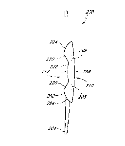
combination of masked IOL features for particular patients.
101601 Figures 6-7 illustrate additional embodiments of intraocular
lenses 600,
700. The posterior surface and anterior surface of an intraocular lens can
have a variety of
curvatures. For example, the posterior surface and/or the anterior surface can
be concave or
convex. Figures 6A-B illustrates an intraocular lens 600 with a concave
posterior surface 610
with an anterior surface 612 to create a positive optical power lens. Figures
7A-B illustrate
an intraocular lens 700 with a concave posterior surface 710 with an anterior
surface 712 to
create a negative optical power lens. Both intraocular lenses 600, 700 have a
second portion
620, 720 to reduce the overall thickness of the intraocular lenses 600, 700.
Both intraocular
lenses 600, 700 also can include a mask 608, 708 to block light that passes
through the
second portion 620, 720. For negative power intraocular lenses, such as the
intraocular lens
700 of Figure 7, the thickness of the central region 732 of the lens body 702
may not be
reduced by the second portion 720. However, the thickness of the outer region
730 of the
lens body 702 can be reduced by the second portion 720 (e.g., transition
zone).
Advantageously, if an intraocular lens has a positive optical power or a
negative optical
power, the thickness of at least a portion of the lens body can be reduced by
having the lens
body include a second portion.
101611 Tables I and II illustrate examples of intraocular lens with
reduced lens
body thicknesses. The column labeled "Reduced- corresponds to an intraocular
lens with a
second portion (e.g. transition zone), and the column labeled "Original- is
corresponds to an
intraocular lens without a second portion. The optic diameter is the diameter
of the outer-
most portion of the lens body with an optical power. The reduction percentage
of the center
region thickness indicated in Tables I and II can be about proportional to the
reduction in the
possible rolled up diameter of a reduced thickness 10L. Therefore, the
reduction percentage
of the center region thickness indicated in Tables I and II can also be about
proportional to
the reduction in the incision size that can be used during implantation of the
IOL in a patient.
An IOL is rolled up and inserted into a tube. and the tube is inserted into
the incision. The
IOL can then be deployed into the intraocular space of the eye. The IOL is
often rolled up as
tight as possible so that open space (e.g., voids) is minimized in a cross-
section of the tube at
-22-
CA 02770735 2012-02-09
WO 2011/020078 PCT/US2010/045548
a location where the implant body has the greatest cross-sectional area that
is generally
parallel with the optical axis of the implant body. Therefore, the cross-
sectional area of the
tube is greater than or equal to the greatest cross-sectional area of the
implant body that is
generally parallel with the optical axis of the implant body. For example, a
36% reduction in
the cross sectional area of the implant body could reduce the cross sectional
area of the tube
by 36% or could reduce the diameter of the tube by about 20%. A minimum
incision length
is generally one-half of the circumference of the tube. Therefore, a 36%
reduction in the
cross sectional area of the implant body can result in about 20% reduction in
incision length.
For example, a 1.8 mm incision could be reduced to about 1.44 mm. A smaller
incision is
beneficial because it avoids post-operative astigmatism.
Table I. Examples of reduced thickness 10Ls with positive optical power.
OpticCenter region thickness Cross section area 9f center
Material Diopter
Diameter [mm] region [mm ]
[Ref
[
Original Reduced Reduction Original Reduced Reduction mm] g
index] [%] [Vo]
Biconvex IOL
5.5 1.4300 18.0 0.94 0.42 55 3.96 2.48 37
5.5 1.4300 24.0 1.20 0.56 53 4.93 3.13 37
5.5 1.4583 18.0 0.77 0.32 58 3.32 2.05 38
5.5 1.4583 24.0 0.96 0.42 56 4.02 2.51 38
6.0 1.4300 18.0 L08 0.50 54 4.76 3.08 35
6.0 1.4300 24.0 1.40 0.62 56 6.04 3.85 36
6.0 1.4583 18.0 0.87 0.37 57 3.92 2.50 36
6.0 1.4583 24.0 1.10 0.50 55 4.88 3.13 36
Sulcus-fixated IOL
5.5 1.4583 5.0 0.34 0.15 56 L75 1.22 30
5.5 1.4583 10.0 0.52 0.20 62 2.43 1.51 38
6.0 1.4583 5.0 0.37 0.17 54 1.95 1.36 30
6.0 1.4583 10.0 0.59 0.21 64 2.86 1.76 38
Table II. Examples of reduced thickness 10Ls with negative optical power.
-23-
CA 02770735 2012-02-09
WO 2011/020078 PCT/US2010/045548
Cross section area of outer
OpticOuter region thickness
Diameter Material Diopter region
[mm]
[mmA2]
[Ref. Reduction Original Reduced Reduction
[mm] Original Reduced
index] [%]rYoi
Sulcus-fixated IOL
5.5 1.4583 -5.0 0.26 0.17 35 1.09 0.77 29
5.5 1.4583 -10.0 0.41 0.25 39 1.52 0.97 36
6.0 1.4583 -5.0 0.29 0.20 31 1.12 0.77 31
6.0 1.4583 -10.0 0.48 0.32 33 1.57 0.99 37
101621 Figure 8 illustrates the operation of the intraocular lens 200
of Figures 2A-
B. In use, light enters the anterior surface 212, passes through the lens body
202 and exits the
posterior surface 210 of the intraocular lens 200. The mask 208 is located
such that the mask
208 blocks a substantial portion of the light rays 850 that pass through the
second portion 220
of the anterior surface 212, as illustrated in Figure 8. If the mask 208 did
not block the light
rays 850 that pass through the second portion 220, aberrations would result.
For example, if
the curvature of the second portion 220 is configured to provide a negative or
divergent
optical power, light rays 860 passing through this region would diverge and
not focus, as
illustrated in Figure 8. The light rays 850 that pass through the first
portion 222 and/or the
third portion 224 would have a positive or convergent optical power. If the
first portion 222
and the third portion 224 have a similar curvature or optical power, light
rays 450 entering
the anterior surface 212 and passing through the first portion 222 and/or the
third portion 224
would converge at a common point 870 after passing through the posterior
surface 210, as
illustrated in Figure 8. Figure 9A illustrates an intraocular lens 200
implanted within the
capsular bag 954 of an eye 952. Parallel light rays 950 that pass through the
intraocular lens
200 converge on the retina 956.
101631 The lens body 202 can include one or more materials. In certain
embodiments, the lens body 202 includes two or more materials. For example,
the first
portion 222 and the third portion 224 can include different materials. If the
materials selected
for the first portion 222 and the third portion 224 have different refractive
indexes, the
-24-
CA 02770735 2012-02-09
WO 2011/020078 PCT/US2010/045548
curvature of the first portion 222 and the third portion 224 can be different
to obtain a similar
optical power (e.g. dioptric power) for both portions.
10164]
Generally, the optical power of an intraocular lens is selected for focusing
on far objects. A natural lens can deform to change the focal distance for far
and near
viewing. Conventional artificial intraocular lenses are generally unable to
change the focal
distance. For example, an eye that is presbyopic or where an artificial
intraocular lens has an
optical power for farther distance, light rays that enter the eye and pass
through the cornea
and the natural lens or artificial intraocular lens converge at a point behind
or in front of the
retina and do not converge at a point on the retina. The light rays strike the
retina over a
larger area than if the light rays converged at a point on the retina. The
patient experiences
this as blurred vision, particularly for up-close objects such as when
reading. For such
conditions, the mask 208 of the intraocular lens 200 can be configured with an
aperture such
that only a subset of light rays, e.g. a central portion, are transmitted to
the retina. The mask
208 with an aperture can improve the depth of focus of a human eye. For
example, the
aperture can be a pin-hole aperture. The mask 208 blocks a portion of the
outer light rays
resulting in more focused light rays. The mask 208 can include an annular
region
surrounding an aperture. The aperture can be substantially centrally located
on the mask. For
example, the aperture can be located around a central axis of the mask, also
referred to as the
optical axis of the mask. The aperture of the mask can be circular or any
other shape.
101651 The
mask 208 can be positioned in a variety of locations in or on the
intraocular lens 200. The mask 208 can be through the lens body 202. The mask
208 can be
positioned on the anterior or posterior surface of the lens body 202. In
certain embodiments,
the mask 208 is embedded within the lens body. For example, the mask 208 can
be
positioned substantially at the midway line between the posterior and anterior
surfaces of the
lens body 202. In certain embodiments, the mask 208 is positioned between the
midway line
and the posterior surface of the lens body 202. Certain embodiments include
the mask 208
being positioned midway, one-third or two-thirds between the midway line and
the posterior
surface of the lens body 202. In certain other embodiments, the mask 208 is
positioned
between the midway line and the anterior surface of the lens body 202.
Certain
embodiments include the mask 208 being positioned midway, one-third or two-
thirds
-25-
CA 02770735 2016-12-19
between the midway line and the anterior surface of the lens body 202. If the
transition
zone is on the anterior surface of the implant body and the mask is positioned
to be on or
near the surface of the transition zone on the anterior surface, the mask may
not extend
beyond the transition zone since light even at large angles from the optical
axis that hits or
passes through the transition zone surface would be blocked by the mask.
[0166] In certain embodiments, the mask 208 of an intraocular lens 200
has an
aperture wherein the mask blocks a portion of the light to improve viewing
near objects,
similar to a mask discussed above. Advantageously, the mask 208 can provide as
an
aperture and can block a portion light that may not converging on the retina
956 and also
block light that passes through the second portion 220, creating aberrations,
as described
above. In certain embodiments, the aperture of the mask 208 has a diameter of
about 1 to
2 mm. In certain embodiments, the mask 208 has an outer perimeter with a
diameter of
about 3 to 5 mm.
[0167] In certain embodiments, the third portion 224 of intraocular lens
200 can
improve low light vision. As the pupil of the eye enlarges, eventually light
rays will enter
and pass through the third portion 224 of the intraocular lens 200. As
illustrated in Figure
9, if the pupil 958 of the eye 952 is large enough so that light rays 950 pass
through the
third portion 224 of the intraocular lens 200, additional light rays 950 will
strike the retina.
As discussed above, the intraocular lens 200 can have an optical power to
correct for
viewing far objects so that light rays from a far object are focused at one
point on the retina.
Near objects during low light conditions may result in an unfocused image if
the intraocular
lens 200 has an optical power to view far objects.
[0168] The mask 208 can have different degrees of opacity. For example,
the
mask 208 can block substantially all of visible light or may block a portion
of visible light.
The opacity of the mask 208 may also vary in different regions of the mask
208. In certain
embodiments, the opacity of the outer edge and/or the inner edge of the mask
208 is less
than the central region of the mask 208. The opacity in different regions may
transition
abruptly or have a gradient transition. Additional examples of opacity
transitions can be
found in U.S. Patents 5,662,706, 5,905,561 and 5,965,330.
-26-
CA 02770735 2012-02-09
WO 2011/020078 PCT/US2010/045548
10169] A
conventional intraocular lens 1000 is illustrated in Figures 10A-B. By
having a recessed portion on the posterior surface 310 (created by second
portions 314)
and/or the anterior surface 312 (created by second portion 320) of the lens
body 302, the
maximum thickness of the intraocular lens 300 is reduced compared to a
conventional lens
body 1002 without such portions, as shown in Figure 10B. The cross-sectional
thickness of
the lens body 1002 is generally dependent on the optical power of the
intraocular lens 1000
and the material of the lens body 1002. In particular, the central region of
the lens body 1002
is generally the thickest section of the intraocular lens 1000 with a central
region cross-
sectional thickness 1006. In certain embodiments disclosed herein, a lens body
202 of an
intraocular lens 200 has a central region thickness 206 less than the central
region thickness
1006 of other common lens bodies. In the embodiment of Figure 3B, the
thickness 306 is
further reduced compared to a conventional intraocular lens 1000.
[0170]
Generally, as discussed above, intraocular lenses are implanted into the
eye by rolling up an intraocular lens and inserting the rolled up intraocular
lens into a tube.
One advantage to a thinner lens body is that it the intraocular lens can be
more tightly rolled
up resulting in being able to use a small tube and a small incision. Another
advantage to a
thinner lens body is that the intraocular lens can decrease risks associated
with implanting in
different locations within the eye. For example, an intraocular lens 200 can
be implanted
within the anterior chamber. An intraocular lens 200 can also be positioned
within the
posterior chamber so that the first portion 216 of the posterior surface 210
floats above the
natural crystalline lens. The potential for contact between the posterior
surface 210 of the
intraocular lens 200 and the natural crystalline lens will be reduced because
the reduced
thickness of the intraocular lens 200. For example, the intraocular lens 200
can be coupled
with or attached to the ciliary sulcus (sometimes referred to herein as -
sulcus-fixated'). An
intraocular lens 200 can also be implanted in the capsular bag, as illustrated
in Figure 9.
Depending on the location of the intraocular lens within the eye, dimensions
of the
intraocular lens 200 including but not limited to the aperture of the mask 208
may be
adjusted.
[0171] The
intraocular lens 200 and/or the lens body 202 can be made from one
or more materials. In certain embodiments, the intraocular lens 200 and/or the
lens body 202
-27-
CA 02770735 2016-12-19
can comprise polymers (e.g. PMMA, PVDF, polypropylene, polycarbonate, PEEK,
polyethylene, acrylic copolymers, polystyrene, PVC, polysulfone), hydrogels,
and silicone.
I. MASKS PROVIDING DEPTH OF FOCUS CORRECTION
[0172] A variety of variations of masks that can be positioned on or
within the
implant body 2014 are discussed herein, and also described in U.S. Patent No.
7,628,810,
U.S. Patent Publication No. 2006/0113054, and U.S. Patent Publication No.
2006/0265058.
Figure 11A illustrates one embodiment of a mask 2034a. The mask 2034a can
include an
annular region 2036a surrounding a pinhole opening or aperture 2038a
substantially
centrally located on the mask 2034a. The pinhole aperture 2038a can be
generally located
around a central axis 2039a, referred to herein as the optical axis of the
mask 2034a. The
pinhole aperture 2038a can be in the shape of a circle. Figure 11B illustrates
another
embodiment of a mask 2034b similar to the mask 2034a illustrated in Figure
11A. The
annular region 2036a of the mask 2034a of Figure 11A has a curvature from the
outer
periphery to the inner periphery of the annular region 2036a; while the
annular region
2036b of the mask 2034b of Figure 11B is substantially flat.
[0173] The mask can have dimensions configured to function with the
implant
body to improve a patient's vision. For example, the thickness of the mask can
vary
depending on the location of the mask relative to the implant body. For
example, if the
mask is embedded within the implant body, the mask can have a thickness
greater than zero
and less than the thickness of the implant body. Alternatively, if the mask is
coupled to a
surface of the implant body, the mask may preferably have a thickness no
greater than
necessary to have desired opacity so that the mask does not add additional
thickness to the
intraocular lens. In certain embodiments, the mask has a thickness of greater
than zero and
less than about 0.5 mm. In one embodiment, the mask has a thickness of about
0.25 mm.
If the mask is on or near the surface of the transition zone, the mask can
have a shape similar
or the same as the transition zone.
[0174] The mask may have a constant thickness, as discussed below.
However,
in some embodiments, the thickness of the mask may vary between the inner
periphery
(near the aperture 2038) and the outer periphery. Figure 12 shows a mask 2034k
that has
a gradually
-28-
CA 02770735 2012-02-09
WO 2011/020078 PCT/US2010/045548
decreasing thickness from the inner periphery to the outer periphery. Figure
13 shows a mask
20341 that has a gradually increasing thickness from the inner periphery to
the outer
periphery. Other cross-sectional profiles are also possible.
[01751 The annular region 2036 can be at least partially opaque or can
be
completely opaque. The degree of opacity of the annular region 2036 prevents
at least some
or substantially all light from being transmitted through the mask 2032.
Opacity of the
annular region 2036 may be achieved in any of several different ways.
101761 For example, in one embodiment, the material used to make mask
2034
may be naturally opaque. Alternatively, the material used to make the mask
2034 may be
substantially clear, but treated with a dye or other pigmentation agent to
render region 2036
substantially or completely opaque. In still another example, the surface of
the mask 2034
may be treated physically or chemically (such as by etching) to alter the
refractive and
transmissive properties of the mask 2034 and make it less transmissive to
light.
101771 In still another alternative, the surface of the mask 2034 may
be treated
with a particulate deposited thereon. For example, the surface of the mask
2034 may be
deposited with particulate of titanium, gold or carbon to provide opacity to
the surface of the
mask 2034. In another alternative, the particulate may be encapsulated within
the interior of
the mask 2034, as generally shown in Figure 14. Finally, the mask 2034 may be
patterned to
provide areas of varying light transmissivity.
101781 In another embodiment, the mask may be formed from co-extruded
rods
made of material having different light transmissive properties. The co-
extruded rod may
then be sliced to provide disks for a plurality of masks, such as those
described herein.
101791 Other embodiments employ different ways of controlling the light
transmissivity through a mask. For example, the mask may be a gel-filled disk,
as shown in
Figure 14. The gel may be a hydrogel or collagen, or other suitable material
that is
biocompatible with the mask material and can be introduced into the interior
of the mask.
The gel within the mask may include particulate 2066 suspended within the gel.
Examples of
suitable particulate are gold. titanium, and carbon particulate. which, as
discussed above. may
alternatively be deposited on the surface of the mask.
-29-
CA 02770735 2016-12-19
[0180] The material of the mask 2034 may be any polymeric material.
Where
the mask 2034 is applied to the intraocular implant, the material of the mask
2034 should
be biocompatible. Where a gel is used, the material is suitable for holding a
gel. Examples
of suitable materials for the mask 2034 include the preferred
polymethylmethacrylate or
other suitable polymers or co-polymers, such as hydrogels, and the like. Of
course, as
indicated above, for non-gel-filled materials, a preferred material may be a
fibrous material,
such as a Dacron mesh.
[0181] Figures 15 and 16 illustrate one embodiment where a mask 2034w
comprises a plurality of nanites 2068. "Nanites" are small particulate
structures that have
been adapted to selectively transmit or block light entering the eye of the
patient. The
particles may be of a very small size typical of the particles used in
nanotechnology
applications. The nanites 2068 are suspended in the gel or otherwise inserted
into the
interior of the mask 2034w, as generally shown in Figures 15 and 16. The
nanites 2068
can be preprogrammed to respond to different light environments.
[0182] Thus, as shown in Figure 15, in a high light environment, the
nanites
2068 turn and position themselves to substantially and selectively block some
of the light
from entering the eye. However, in a low light environment where it is
desirable for more
light to enter the eye, nanites may respond by turning or be otherwise
positioned to allow
more light to enter the eye, as shown in Figure 16.
[0183] Nano-devices or nanites are crystalline structures grown in
laboratories.
The nanites may be treated such that they are receptive to different stimuli
such as light. In
accordance with one aspect of certain embodiments, the nanites can be imparted
with
energy where, in response to a low light and high light environments, they
rotate in the
manner described above and generally shown in Figure 16.
[0184] Nanoscale devices and systems and their fabrication are described
in
Smith et al., "Nanofabrication," Physics Today, February 1990, pp. 24-30 and
in
Craighead, "Nanoelectromechanical Systems," Science, November 24, 2000, Vol.
290, pp.
1502-1505. Tailoring the properties of small-sized particles for optical
applications is
disclosed in Chen et al. "Diffractive Phase Elements Based on Two-Dimensional
Artificial
Dielectrics," Optics Letters, January 15, 1995, Vol.. 20, No. 2, pp. 121-123.
[0185] In additional embodiments, a photochromic material can be used as
the
mask or in addition to mask. Under bright light conditions, the photochromic
material can
darken thereby creating a mask and enhancing near vision. Under dim light
conditions, the
-30-
CA 02770735 2016-12-19
photochromic lightens, which allows more light to pass through to the retina.
In certain
embodiments, under dim light conditions, the photochromic lightens to expose
an optic of
the intraocular implant.
[0186] The mask can have different degrees of opacity. For example, the
mask
can block substantially all of visible light or may block a portion of visible
light. The
opacity of the mask may also vary in different regions of the mask. In certain
embodiments,
the opacity of the outer edge and/or the inner edge of the mask is less than
the central region
of the mask. The opacity in different regions may transition abruptly or have
a gradient
transition. Additional examples of opacity transitions can be found in U.S.
Patents
5,662,706, 5,905,561 and 5,965,330.
[0187] In some embodiments, the mask 2034 is attached or fixed to the
eye
2010 by support strands 2072 and 2074 shown in Figure17 and generally
described in U.S.
Patent No. 4,976,732.
[0188] Further mask details are disclosed in U.S. Patent No. 4,976,732,
issued
December 11, 1990 and in U.S. Patent Publication No. 2005/0033420.
[0189] An advantage to embodiments that include a mask with an aperture
(e.g.,
pin-hole aperture) described herein over multifocal IOLs, contact lenses, or
treatments of
the cornea is that all of these latter approaches divide the available light
coming through
the aperture into two or more foci while a mask approach has a single focus
(monofocal). This limitation forces designers of multifocal optics to choose
how much of
the light is directed to each focal point, and to deal with the effects of the
unfocused light
that is always present in any image. In order to maximize acuity at the
important distances
of infinity (>6M) and 40 cm (normal reading distance), it is typical to
provide little or no
light focused at an intermediate distance, and as a result, visual acuity at
these distances is
poor.
[0190] With an aperture to increase depth-of-focus, however, the
intermediate
vision of presbyopic patient is improved significantly. Indeed, the defocus
blur with the
pin-hole aperture is less at intermediate distances than at near. This can be
seen in Figure
59 which is a plot of visual acuity as a function of defocus comparing an
embodiment of
an ophthalmic device with an aperture and with two commercially available
multifocal
IOLs. While greater visual acuity is obtained with the multifocal IOLs at very
close
distances (33 cm, -3D), over the range of 1M (-1D) to 40 cm (-2.5D), the pin-
hole aperture
can outperform a multifocal optic in an intermediate range.
-31-
CA 02770735 2016-12-19
[0191] Visual acuity is measured in logMAR and is the log of the minimum
angle of resolution or the smallest angular spacing that can be seen, and it
is independent
of viewing distance. A logMAR value of 0 means 20/20, 6/6, or a decimal acuity
of 1 at
distance, and equivalent to a near acuity of Jaeger 1 (J1). Defocus is
measured in diopters,
which are the reciprocal of the eye's focal length in meters. Thus, -1D of
defocus means
the eye is focused at 1/1=1 meter. The standard (US and Europe) reading
distance is 40
cm, which is -2.5 D of defocus (1/.4=2.5).
II. UV-RESISTANT POLYMERIC MASK MATERIALS
[0192] Because the mask has a very high surface to volume ratio and is
exposed
to a great deal of sunlight following implantation, the mask preferably
comprises a material
which has good resistance to degradation, including from exposure to
ultraviolet (UV) or
other wavelengths of light. Polymers including a UV absorbing component,
including
those comprising UV absorbing additives or made with UV absorbing monomers
(including co-monomers), may be used in forming masks as disclosed herein
which are
resistant to degradation by UV radiation. Examples of such polymers include,
but are not
limited to, those described in U.S. Patent Nos. 4,985,559 and 4,528,311. In a
preferred
embodiment, the mask comprises a material which itself is resistant to
degradation by UV
radiation. In one embodiment, the mask comprises a polymeric material which is
substantially reflective of or transparent to UV radiation. The lens body may
include a UV
absorbing component in addition to the mask being resistant to degradation by
UV radiation
or the mask may not be
-32-
CA 02770735 2012-02-09
WO 2011/020078 PCT/US2010/045548
resistant to degradation by UV radiation since the UV absorbing component in
the lens body
may prevent degradation of the mask by UV radiation.
10193] Alternatively, the mask may include a component which imparts a
degradation resistive effect, or may be provided with a coating, preferably at
least on the
anterior surface, which imparts degradation resistance. Such components may be
included,
for example, by blending one or more degradation resistant polymers with one
or more other
polymers. Such blends may also comprise additives which provide desirable
properties, such
as UV absorbing materials. In one embodiment, blends preferably comprise a
total of about
1-20 wt.%, including about 1-10 wt.%, 5-15 wt.%, and 10-20 wt.% of one or more
degradation resistant polymers. In another embodiment, blends preferably
comprise a total of
about 80-100 wt.%, including about 80-90 wt.%, 85-95 wt.%, and 90-100 wt.% of
one or
more degradation resistant polymers. In another embodiment, the blend has more
equivalent
proportions of materials, comprising a total of about 40-60 wt.%, including
about 50-60
wt.%, and 40-50 wt.% of one or more degradation resistant polymers. Masks may
also
include blends of different types of degradation resistant polymers, including
those blends
comprising one or more generally UV transparent or reflective polymers with
one or more
polymers incorporating UV absorption additives or monomers. These blends
include those
having a total of about 1-20 wt.%, including about 1-10 wt.%, 5-15 wt.%, and
10-20 wt.% of
one or more generally UV transparent polymers, a total of about 80-100 wt.%,
including
about 80-90 wt.%, 85-95 wt.%, and 90-100 wt.% of one or more generally UV
transparent
polymers, and a total of about 40-60 wt.%, including about 50-60 wt.%, and 40-
50 wt.% of
one or more generally UV transparent polymers. The polymer or polymer blend
may be
mixed with other materials as discussed below, including, but not limited to,
pacification
agents, polyanionic compounds and/or wound healing modulator compounds. When
mixed
with these other materials, the amount of polymer or polymer blend in the
material which
makes up the mask is preferably about 50%-99% by weight, including about 60%-
90% by
weight, about 65-85% by weight. about 70-80% by weight. and about 90-99% by
weight.
10194] Preferred degradation resistant polymers include halogenated
polymers.
Preferred halogenated polymers include fluorinated polymers, that is, polymers
having at
least one carbon-fluorine bond, including highly fluorinated polymers. The
term "highly
-33-
CA 02770735 2012-02-09
WO 2011/020078 PCT/US2010/045548
fluorinated" as it is used herein, is a broad term used in its ordinary sense,
and includes
polymers having at least one carbon-fluorine bond (C-F bond) where the number
of C-F
bonds equals or exceeds the number of carbon-hydrogen bonds (C-I-1 bonds).
Highly
fluorinated materials also include perfluorinated or fully fluorinated
materials, materials
which include other halogen substituents such as chlorine, and mate rials
which include
oxygen- or nitrogen-containing functional groups. For polymeric materials, the
number of
bonds may be counted by referring to the monomer(s) or repeating units which
form the
polymer, and in the case of a copolymer, by the relative amounts of each
monomer (on a
molar basis).
[0195] Preferred highly fluorinated polymers include, but are not
limited to,
polytetrafluoroethylene (PFTE or Teflon()); polyvinylidene fluoride (PVDF or
Kynar0),
poly-1,1,2-trifluoroethylene; and perfluoroalkoxyethylene (PFA). Other highly
fluorinated
polymers include, but are not limited to, homopolymers and copolymers
including one or
more of the following monomer units: tetrafluoroethylene -(CF2-CF2)-;
vinylidene fluoride -
(CF2-CH2)-; 1,1,2-trifluoroethylene -(CF2-CHF)-; hexafluoropropene -(CF(CF3)-
CF2)-;
vinyl fluoride -(CH2-CHF)- (homopolymer is not "highly fluorinated"); oxygen-
containing
monomers such as -(0-CF2)-, -(0-CF2-CF2)-, -(0-CF(CF3)-CF2)-; chlorine-
containing
monomers such as -(CF2-CFCI)-. Other fluorinated polymers, such as fluorinated
polyimide
and fluorinated acrylates, having sufficient degrees of fluorination are also
contemplated as
highly fluorinated polymers for use in masks according to preferred
embodiments. The
homopolymers and copolymers described herein are available commercially and/or
methods
for their preparation from commercially available materials are widely
published and known
to those in the polymer arts.
[0196] Although highly fluorinated polymers are preferred, polymers
having one
or more carbon-fluorine bonds but not falling within the definition of "highly
fluorinated"
polymers as discussed above, may also be used. Such polymers include co-
polymers formed
from one or more of the monomers in the preceding paragraph with ethylene,
vinyl fluoride
or other monomer to form a polymeric material having a greater number of C-H
bonds than
C-F bonds. Other fluorinated polymers, such as fluorinated polyimide, may also
be used.
Other materials that could be used in some applications, alone or in
combination with a
-34-
CA 02770735 2012-02-09
WO 2011/020078 PCT/US2010/045548
fluorinated or a highly fluorinated polymer, are described in U.S. Patent No.
4,985,559 and in
U.S. Patent No. 4,528,311, both of which are hereby incorporated by reference
herein in their
entirety.
101971 The preceding definition of highly fluorinated is best
illustrated by means
of a few examples. One preferred UV-resistant polymeric material is
polyvinylidene fluoride
(PVDF), having a structure represented by the formula: -(CF2-CH2)n-. Each
repeating unit
has two C-H bonds, and two C-F bonds. Because the number of C-F bonds equals
or exceeds
the number of C-H bonds, PVDF homopolymer is a "highly fluorinated" polymer.
Another
material is a tetrafluoroethylene/vinyl fluoride copolymer formed from these
two monomers
in a 2:1 molar ratio. Regardless of whether the copolymer formed is block,
random or any
other arrangement, from the 2:1 tetrafluoroethylene:vinyl fluoride composition
one can
presume a "repeating unit" comprising two tetrafluoroethylene units, each
having four C-F
bonds, and one vinyl fluoride unit having three C-H bonds and one C-F bond.
The total
bonds for two tetrafluoroethylenes and one vinyl fluoride are nine C-F bonds,
and three C-H
bonds. Because the number of C-F bonds equals or exceeds the number of C-H
bonds, this
copolymer is considered highly fluorinated.
101981 Certain highly fluorinated polymers, such as PVDF, have one or
more
desirable characteristics, such as being relatively chemically inert and
having a relatively high
UV transparency as compared to their non-fluorinated or less highly
fluorinated counterpart
polymers. Although the applicant does not intend to be bound by theory, it is
postulated that
the electronegativity of fluorine may be responsible for many of the desirable
properties of
the materials having relatively large numbers of C-F bonds.
101991 In preferred embodiments, at least a portion of the highly
fluorinated
polymer material forming the mask comprises an pacification agent which
imparts a desired
degree of opacity. In one embodiment, the pacification agent provides
sufficient opacity to
produce the depth of field improvements described herein, e.g... in
combination with a
transmissive aperture. In one embodiment. the pacification agent renders the
material
opaque. In another embodiment. the pacification agent prevents transmission
of about 90
percent or more of incident light. In another embodiment, the pacification
agent renders the
material opaque. In another embodiment, the pacification agent prevents
transmission of
-35-
CA 02770735 2012-02-09
WO 2011/020078 PCT/US2010/045548
about 80 percent or more of incident light. Preferred opacification agents
include, but are not
limited to organic dyes and/or pigments, preferably black ones, such as azo
dyes, hematoxylin
black, and Sudan black; inorganic dyes and/or pigments, including metal oxides
such as iron
oxide black and ilminite, silicon carbide and carbon (e.g. carbon black,
submicron powdered
carbon). The foregoing materials may be used alone or in combination with one
or more
other materials. The opacification agent may be applied to one or more
surfaces of the mask
on all or some of the surface, or it may be mixed or combined with the
polymeric material
(e.g. blended during the polymer melt phase). Although any of the foregoing
materials may
be used, carbon has been found to be especially useful in that it does not
fade over time as do
many organic dyes, and that it also aids the UV stability of the material by
absorbing UV
radiation. In one embodiment, carbon may be mixed with polyvinylidene fluoride
(PVDF) or
other polymer composition comprising highly fluorinated polymer such that the
carbon
comprises about 2% to about 20% by weight of the resulting composition,
including about
10% to about 15% by weight, including about 12%, about 13%, and about 14% by
weight of
the resulting composition.
102001 Some opacification agents, such as pigments, which are added to
blacken,
darken or opacify portions of the mask may cause the mask to absorb incident
radiation to a
greater degree than mask material not including such agents. Because the
matrix polymer
that carries or includes the pigments may be subject to degradation from the
absorbed
radiation, it is preferred that the mask, which is thin and has a high surface
area making it
vulnerable to environmental degradation, be made of a material which is itself
resistant to
degradation such as from UV radiation, or that it be generally transparent to
or non-absorbing
of UV radiation. Use of a highly UV resistant and degradation resistant
material, such as
PVDF, which is highly transparent to UV radiation, allows for greater
flexibility in choice of
opacification agent because possible damage to the polymer caused by selection
of a
particular opacification agent is greatly reduced.
10201] A number of variations of the foregoing embodiments of
degradation
resistant constructions are contemplated. In one variation, a mask is made
almost exclusively
of a material that is not subject to UV degradation. For example, the mask can
be made of a
metal, a highly fluorinated polymer, carbon (e.g., graphene, pure carbon), or
another similar
-36-
CA 02770735 2016-12-19
material. Construction of the mask with metal is discussed in more detail in
U.S. Patent
Publication No. 2006/0118263, "Method of Making an Ocular Implant" and also in
U.S.
Patent Publication No. 2006/0113054, "Method of Making an Ocular Implant". As
used
in this context, "exclusively" is a broad term that allows for the presence of
some non-
functional materials (e.g., impurities) and for an opacification agent, as
discussed above.
In other embodiments, the mask can include a combination of materials. For
example, in
one variation, the mask is formed primarily of any implantable material and is
coated with
a UV resistant material. In another variation, the mask includes one or more
UV
degradation inhibitors and/or one or more UV degradation resistant polymers in
sufficient
concentration such that the mask under normal use conditions will maintain
sufficient
functionality in terms of degradation to remain medically effective for at
least about 5 years,
preferably at least about 10 years, and in certain implementations at least
about 20 years.
[0202] Figure 23 is a flow chart illustrating methods for making a
masked
intraocular implant from a mask comprising a highly fluorinated polymer and an
opacification agent. The method of Figure 23 includes a first method 3014 of
making a
mask of highly fluorinated polymer and opacification agent and a second method
3026 of
making an intraocular implant with the mask made from the first method 3014.
[0203] At step 3000, a liquid form of a polymer is created by dissolving
polyvinylidene fluoride (PVDF) pellets into a solvent such as dimethyl
acetamide (DMAC
or DMA) using heat until the PVDF has completely dissolved. In one embodiment,
the
solution may be mixed for a minimum of 12 hours to ensure that the PVDF has
completely
dissolved. At step 3200, the PVDF/DMAC solution is mixed with an opacification
agent,
such as a dye or carbon black, using a high speed shear mixer. In one
embodiment, the
carbon black comprises 13% by weight of the resulting composition while the
PVDF
comprises 87% by weight of the resulting composition. At step 3300, the
PVDF/carbon
black solution is optionally milled in a high speed mill, for example an Eiger
high speed
mill, to break up any large carbon agglomerates in the solution. The
PVDF/carbon black
solution may be run through the mill a second time to further break up any
carbon
agglomerates. At step 3400, the resulting solution is applied to a silicon
wafer to create a
polymer film on the silicon disk.
-37-
CA 02770735 2012-02-09
WO 2011/020078 PCT/US2010/045548
Here, approximately 55g of the PVDF/carbon black solution is poured into a
dispensing
ban-el for application on a silicon wafer. The silicon disk is placed on the
spinner of a spin
casting machine and the dispensing barrel is used to apply a bead of
PVDF/carbon black
solution to the silicon wafer in a circular pattern, leaving the center 1"
diameter of the disk
empty. The spinner cycle is actuated to disperse the PVDF/carbon black
solution over the
disk, forming a uniform 10 micron thick film. A polymer film may also be
deposited, spray
coated, etc. to a silicon wafer. The coated silicon disk is then placed on a
hot-plate to
evaporate the DMAC. At step 3500, the coated silicon wafer is placed under an
excimer
laser. A laser cutting mask is mounted in the laser and the laser is actuated.
Using the laser
cutting mask, approximately 150 mask patterns are laser machined into the
PVDF/carbon
black film. The mask patterns may also be formed using a punch technique,
electron beam,
etch, etc. The mask patterns are arranged such that the material extending
approximately
5inm from the edge of the silicon disk is not used. During the laser
machining, the silicon
disk may be bathed in nitrogen gas in order to cool the surface. At step 3600,
the laser
machined masks are removed from the silicon disk using a razor blade. An
optional step may
include placing the laser-machined mask into a forming mold. The mold can be
any shape
desired, such as a flat mold, a convex mold, a concave mold, or a mold with a
more complex
shape. The mask may be placed in the bottom half of the forming mold in one
technique.
The top half of the forming mold can be placed on top of the mask and the
molds can be
placed in an oven at about 160 C. The molds are then heated and baked to form
the masks.
The molds are allowed to bake for approximately two hours at approximately 160
C. After
two hours the oven temperature is reduced to about 30 C and the masks are
baked for
approximately two hours or until the oven temperature has dropped to below
around 40 C.
102041 At step 3016, the inlay (e.g. mask) made in the first method
3014 is placed
in a mold form. In one embodiment, silicone or other lens material is injected
into the mold
form and around the inlay. At step 3018, the silicone is cured to form an
implant body. At
step 3020, the intraocular implant is polished, and at step 3022. the implant
body is extracted
from the mold form. At step 3024. one or more haptics may be attached (e.g.
bonded) to the
implant body to form an intraocular implant. Step 3024 may be included for a
three piece
IOL design, but may not be needed for other designs. In certain embodiments,
the one or
-38-
CA 02770735 2012-02-09
WO 2011/020078 PCT/US2010/045548
more haptics are formed with the implant body during the injection process.
For example,
the implant body may be lathed and the haptics milled from a single piece. The
intraocular
implant can be subsequently inspected (e.g. cosmetic, diopter, resolution).
IV. MASKS CONFIGURED TO REDUCE VISIBLE DIFFRACTION PATTERNS
102051 Many of the foregoing masks can be used to improve the depth of
focus of
a patient. Various additional mask embodiments are discussed below. Some of
the
embodiments described below include light transmission holes through the mask
annular
region to change the amount of light blocked by the annular region. Light
transmission holes
through the mask can improve a patient's dim or low light vision. In certain
arrangements of
light transmission holes, the light transmission holes may generate
diffraction patterns that
interfere with the vision improving effect of the masks described herein.
Accordingly,
certain masks are described herein that include light transmission holes that
do not generate
diffraction patterns or otherwise interfere with the vision enhancing effects
of the mask
embodiments.
102061 Figures 18-19 show one embodiment of a mask 2100 configured to
increase depth of focus of an eye of a patient with presbyopia. The mask 2100
is similar to
the masks hereinbefore described, except as described differently below. The
mask 2100 can
be made of the materials discussed herein, including those discussed above.
Also, the mask
2100 can be formed by any suitable process. The mask 2100 is configured to be
applied to an
IOL.
102071 In one embodiment, the mask 2100 includes a body 2104 that has
an
anterior surface 2108 and a posterior surface 2112. The body 2104 may be
formed of any
suitable material, including at least one of an open cell foam material, an
expanded solid
material, and a substantially opaque material. In one embodiment, the material
used to form
the body 2104 has relatively high water content. In other embodiments, the
materials that can
be used to form the body 2104 include polymers (e.g. PMMA. PVDF,
polypropylene,
polycarbonate, PEEK, polyethylene. acrylic copolymers (e.g., hydrophobic or
hydrophilic),
polystyrene, PVC, polysulfone), hydrogels, silicone, metals, metal alloys, or
carbon (e.g.,
graphene, pure carbon).
-39-
CA 02770735 2012-02-09
WO 2011/020078 PCT/US2010/045548
102081 In one embodiment, the mask 2100 includes a light transmission
hole
arrangement 2116. The light transmission hole arrangement 2116 may comprise a
plurality
of holes 2120. The holes 2120 are shown on only a portion of the mask 2100,
but the holes
2120 preferably are located throughout the body 2104 in one embodiment. In one
embodiment, the holes 2120 are arranged in a hex pattern, which is illustrated
by a plurality
of locations 2120' in Figure 20A. As discussed below, a plurality of locations
may be
defined and later used in the later formation of a plurality of holes 2120 on
the mask 2100.
The mask 2100 has an outer periphery 2124 that defines an outer edge of the
body 2104. In
some embodiments, the mask 2100 includes an aperture 2128 at least partially
surrounded by
the outer periphery 2124 and a non-transmissive portion 2132 located between
the outer
periphery 2124 and the aperture 2128.
[0209] Preferably the mask 2100 is symmetrical, e.g., symmetrical about
a mask
axis 2136. In one embodiment, the outer periphery 2124 of the mask 2100 is
circular. The
mask in general has a diameter within the range of from about 3 mm to about 8
mm, often
within the range of from about 3.5 mm to about 6 mm, and less than about 6 mm
in one
embodiment. In another embodiment, the mask is circular and has a diameter in
the range of
4 to 6 mm. In another embodiment, the mask 2100 is circular and has a diameter
of less than
4 mm. The outer periphery 2124 has a diameter of about 3.8 mm in another
embodiment. In
some embodiments, masks that are asymmetrical or that are not symmetrical
about a mask
axis provide benefits, such as enabling a mask to be located or maintained in
a selected
position with respect to the anatomy of the eye.
102101 The body 2104 of the mask 2100 may be configured to be coupled
with a
particular intraocular lens design, either of reduced thickness design or of
conventional
design. For example, where the mask 2100 is to be coupled with a particular
IOL that has
curvature, the body 2104 may be provided with a corresponding amount of
curvature along
the mask axis 2136 that corresponds to the curvature. Likewise, the body 2104
may be
provided with corresponding shape to accommodate IOL transition zones.
[0211] In some embodiments, the mask 2100 has a desired amount of
optical
power. Optical power may be provided by configuring the at least one of the
anterior and
posterior surfaces 2108, 2112 with curvature. In one embodiment, the anterior
and posterior
-40-
CA 02770735 2012-02-09
WO 2011/020078 PCT/US2010/045548
surfaces 2108, 2112 are provided with different amounts of curvature. In this
embodiment,
the mask 2100 has varying thickness from the outer periphery 2124 to the
aperture 2128.
102121 In one embodiment, one of the anterior surface 2108 and the
posterior
surface 2112 of the body 2104 is substantially planar. In one planar
embodiment, very little
or no uniform curvature can be measured across the planar surface. In another
embodiment,
both of the anterior and posterior surfaces 2108, 2112 are substantially
planar. In general, the
thickness of the body 2104 of the mask 2100 may be within the range of from
greater than
zero to about 0.5 mm. In another embodiment, the thickness 2138 of the mask
2100 is about
0.25 mm. 102011 A substantially planar mask has several advantages over a non-
planar
mask. For example, a substantially planar mask can be fabricated more easily
than one that
has to be formed to a particular curvature. In particular, the process steps
involved in
inducing curvature in the mask 2100 can be eliminated.
102131 The aperture 2128 is configured to transmit substantially all
incident light
along the mask axis 2136. The non-transmissive portion 2132 surrounds at least
a portion of
the aperture 2128 and substantially prevents transmission of incident light
thereon. As
discussed in connection with the above masks, the aperture 2128 may be a
through-hole in
the body 2104 or a substantially light transmissive (e.g., transparent)
portion thereof. The
aperture 2128 of the mask 2100 generally is defined within the outer periphery
2124 of the
mask 2100. The aperture 2128 may take any of suitable configurations, such as
those
described above.
102141 In one embodiment, the aperture 2128 is substantially circular
and is
substantially centered in the mask 2100. The size of the aperture 2128 may be
any size that is
effective to increase the depth of focus of an eye of a patient suffering from
presbyopia. In
particular, the size of the aperture 2128 is dependent on the location of the
mask within the
eye (e.g.., distance from the retina). For example, in the intraocular space
of the eye, the
aperture 2128 can be circular. having a diameter of less than about 2 mm in
one embodiment.
In another embodiment. the diameter of the aperture is between about 1.1 mm
and about 1.6
mm. In another embodiment. the aperture 2128 is circular and has a diameter of
about 1.6
mm or less. In a further embodiment, the diameter of the aperture is about mm.
Most
-41-
CA 02770735 2012-02-09
WO 2011/020078 PCT/US2010/045548
apertures will have a diameter within the range of from about 0.85 mm to about
2.2 mm, and
often within the range of from about 1.1 mm to about 1.7 mm.
102151 In certain embodiments, the aperture 2128 includes an optical
power
and/or refractive properties. For example, the aperture 2128 can include an
optic and can
have an optical power (e.g. positive or negative optical power). In certain
embodiments, the
aperture 2128 can correct for refractive errors of an eye.
102161 The non-transmissive portion 2132 is configured to prevent
transmission
of radiant energy through the mask 2100. For example, in one embodiment, the
non-
transmissive portion 2132 prevents transmission of substantially all of at
least a portion of the
spectrum of the incident radiant energy. In one embodiment, the non-
transmissive portion
2132 is configured to prevent transmission of substantially all visible light,
e.g., radiant
energy in the electromagnetic spectrum that is visible to the human eye. The
non-
transmissive portion 2132 may substantially prevent transmission of radiant
energy outside
the range visible to humans in some embodiments.
10217J As discussed above, preventing transmission of light through the
non-
transmissive portion 2132 decreases the amount of light that reaches the
retina and the fovea
that would not converge at the retina and fovea to form a sharp image. As
discussed above,
the size of the aperture 2128 is such that the light transmitted therethrough
generally
converges at the retina or fovea. Accordingly, a much sharper image is
presented to the eye
than would otherwise be the case without the mask 2100.
102181 In one embodiment, the non-transmissive portion 2132 prevents
transmission of at least about 90 percent of incident light. In another
embodiment, the non-
transmissive portion 2132 prevents transmission of at least about 95 percent
of all incident
light. The non-transmissive portion 2132 of the mask 2100 may be configured to
be
substantially opaque to prevent the transmission of light. As used herein the
term "opaque-
is intended to indicate a transmission of no more than about 2% of incident
visible light. In
one embodiment, at least a portion of the body 2104 is configured to be opaque
to more than
99 percent of the light incident thereon.
102191 As discussed above, the non-transmissive portion 2132 may be
configured
to prevent transmission of light without absorbing the incident light. For
example, the mask
-42-
CA 02770735 2016-12-19
2100 could be made reflective or could be made to interact with the light in a
more complex
manner, as discussed in U.S. Patent No. 6,554,424, issued April 29, 2003.
[0220] As discussed above, the mask 2100 also has light transmission
holes that
in some embodiments comprises the plurality of holes 2120. The presence of the
plurality
of holes 2120 (or other light transmission structures) may affect the
transmission of light
through the non-transmissive portion 2132 by potentially allowing more light
to pass
through the mask 2100. In one embodiment, the non-transmissive portion 2132 is
configured to absorb about 98 percent or more of the incident light from
passing through
the mask 2100 without holes 2120 being present. The presence of the plurality
of holes
2120 allows more light to pass through the non-transmissive portion 2132 such
that only
about 95 percent of the light incident on the non-transmissive portion 2132 is
prevented
from passing through the non-transmissive portion 2132. The holes 2120 may
reduce the
benefit of the aperture 2128 on the depth of focus of the eye by allowing more
light to pass
through the non-transmissive portion to the retina.
[0221] As discussed above, the holes 2120 of the mask 2100 shown in
Figure
18A may be located anywhere on the mask 2100. Other mask embodiments described
herein below locate substantially all of the light transmission holes are in
one or more
regions of a mask.
[0222] The holes 2120 of Figure 18A extend at least partially between
the
anterior surface 2108 and the posterior surface 2112 of the mask 2100. In one
embodiment,
each of the holes 2120 includes a hole entrance 2160 and a hole exit 2164. The
hole
entrance 2160 is located adjacent to the anterior surface 2108 of the mask
2100. The hole
exit 2164 is located adjacent to the posterior surface 2112 of the mask 2100.
In one
embodiment, each of the holes 2120 extends the entire distance between the
anterior surface
2108 and the posterior surface 2112 of the mask 2100.
[0223] In one embodiment, the holes 2120 have a diameter in the range of
about
0.002 mm to about 0.050 mm. In certain embodiments, the holes 2120 have a
diameter of
about 0.005 mm or more. In another embodiment, the holes have a diameter of
about 0.020
mm. In another embodiment, the holes have a diameter of about 0.025 mm. In
another
-43-
CA 02770735 2012-02-09
WO 2011/020078 PCT/US2010/045548
embodiment, the holes have a diameter of about 0.027 mm. In another
embodiment, the
holes 2120 have a diameter in the range of about 0.020 mm to about 0.029 mm.
In one
embodiment, the number of holes in the plurality of holes 2120 is selected
such that the sum
of the surface areas of the hole entrances 2140 of all the holes 2100
comprises about 5
percent or more of surface area of the anterior surface 2108 of the mask 2100.
In another
embodiment, the number of holes 2120 is selected such that the sum of the
surface areas of
the hole exits 2164 of all the holes 2120 comprises about 5 percent or more of
surface area of
the posterior surface 2112 of the mask 2100. In another embodiment, the number
of holes
2120 is selected such that the sum of the surface areas of the hole exits 2164
of all the holes
2120 comprises about 5 percent or more of surface area of the posterior
surface 2112 of the
mask 2112 and the sum of the surface areas of the hole entrances 2140 of all
the holes 2120
comprises about 5 percent or more of surface area of the anterior surface 2108
of the mask
2100. In another embodiment, the plurality of holes 2120 may comprise about
1600
microperforations. In another embodiment, the plurality of holes 2120
comprises about 8400
microperforations.
102241 Each of the holes 2120 may have a relatively constant cross-
sectional area.
In one embodiment, the cross-sectional shape of each of the holes 2120 is
substantially
circular. Each of the holes 2120 may comprise a cylinder extending between the
anterior
surface 2108 and the posterior surface 2112.
102251 The relative position of the holes 2120 is of interest in some
embodiments.
As discussed above, the holes 2120 of the mask 2100 are hex-packed, e.g.,
arranged in a hex
pattern. In particular. in this embodiment, each of the holes 2120 is
separated from the
adjacent holes 2120 by a substantially constant distance, sometimes referred
to herein as a
hole pitch. In one embodiment, the hole pitch is about 0.045 mm.
102261 In a hex pattern, the angles between lines of symmetry are
approximately
43 degrees. The spacing between any two neighboring holes is generally within
the range of
from about 30 microns to about 100 microns, and, in one embodiment, is
approximately 43
microns. The hole diameter is generally within the range of from about 2
microns to about
100 microns, and in one embodiment, is approximately 20 microns. The light
transmission is
-44-
CA 02770735 2012-02-09
WO 2011/020078 PCT/US2010/045548
a function of the sum of hole areas as will be understood by those of skill in
the art in view of
the disclosure herein.
102271 Negative visual effects may arise due to the presence of the
light
transmission hole arrangement 2116. For example, in some cases, a hex packed
arrangement
of the holes 2120 can generate diffraction patterns visible to the patient.
For example,
patients might observe a plurality of spots, e.g., six spots, surrounding a
central light with
holes 2120 having a hex patterned.
102281 A variety of techniques are possible that produce advantageous
arrangements of light transmission holes such that diffraction patterns and
other deleterious
visual effects do not substantially inhibit other visual benefits of a mask.
In one embodiment,
where diffraction effects would be observable, the light transmission holes
are arranged to
spread the diffracted light out uniformly across the image to eliminate
observable spots. In
another embodiment, the light transmission holes employ a pattern that
substantially
eliminates diffraction patterns or pushes the patterns to the periphery of the
image.
102291 Figures 20B-20C show two embodiments of patterns of holes 2220'
that
may be applied to a mask that is otherwise substantially similar to the mask
2100. The holes
2220' of the hole patterns of Figures 20B-20C are spaced from each other by a
random hole
spacing or hole pitch. In other embodiments discussed below, holes are spaced
from each
other by a non-uniform amount, not a random amount. In one embodiment, the
holes 2220'
have a substantially uniform shape (cylindrical shafts having a substantially
constant cross-
sectional area). Figure 20C illustrates a plurality of holes 2220' separated
by a random
spacing, wherein the density of the holes is greater than that of Figure 20B.
Generally, the
higher the percentage of the mask body that has holes the more the mask will
allow light to
transmit through the mask. One way to provide a higher percentage of hole area
is to
increase the density of the holes. Increased hole density can also permit
smaller holes to
achieve the same light transmission as is achieved by less dense, larger
holes.
102301 Figure 21A shows a portion of another mask 2200a that is
substantially
similar to the mask 2100. except described differently below. The mask 2200a
can be made
of the materials discussed herein, including those discussed above. The mask
2200a can be
formed by any suitable process, such as those discussed herein and with
variations of such
-45-
CA 02770735 2012-02-09
WO 2011/020078 PCT/US2010/045548
processes. The mask 2200a has a light transmission hole arrangement 2216a that
includes a
plurality of holes 2220a. A substantial number of the holes 2220a have a non-
uniform size.
The holes 2220a may be uniform in cross-sectional shape. The cross-sectional
shape of the
holes 2220a is substantially circular in one embodiment. The holes 2220a may
be circular in
shape and have the same diameter from a hole entrance to a hole exit, but are
otherwise non-
uniform in at least one aspect, e.g., in size. It may be preferable to vary
the size of a
substantial number of the holes by a random amount. In another embodiment, the
holes
2220a are non-uniform (e.g., random) in size and are separated by a non-
uniform (e.g., a
random) spacing.
102311 Figure 21B illustrates another embodiment of a mask 2200b that
is
substantially similar to the mask 2100, except as described differently below.
The mask
2200b can be made of the materials discussed herein. Also, the mask 2200b can
be formed
by any suitable process, such as those discussed herein and with variations of
such processes.
The mask 2200b includes a body 2204b. The mask 2200b has a light transmission
hole
arrangement 2216b that includes a plurality of holes 2220b with a non-uniform
facet
orientation. In particular, each of the holes 2220b has a hole entrance that
may be located at
an anterior surface of the mask 2200b. A facet of the hole entrance is defined
by a portion of
the body 2204b of the mask 2200b surrounding the hole entrance. The facet is
the shape of
the hole entrance at the anterior surface. In one embodiment, most or all the
facets have an
elongate shape, e.g., an oblong shape. with a long axis and a short axis that
is perpendicular
to the long axis. The facets may be substantially uniform in shape. In one
embodiment, the
orientation of facets is not uniform. For example, a substantial number of the
facets may
have a non-uniform orientation. In one arrangement, a substantial number of
the facets have
a random orientation. In some embodiments, the facets are non-uniform (e.g..
random) in
shape and are non-unifomi random) in orientation.
102321 Other embodiments may be provided that vary at least one aspect,
including one or more of the foregoing aspects, of a plurality of holes to
reduce the tendency
of the holes to produce visible diffraction patterns or patterns that
otherwise reduce the vision
improvement that may be provided by a mask with an aperture, such as any of
those
described above. For example, in one embodiment, the hole size, shape, and
orientation of at
-46-
CA 02770735 2012-02-09
WO 2011/020078 PCT/US2010/045548
least a substantial number of the holes may be varied randomly or may be
otherwise non-
uniform. The mask may also be characterized in that at least one of the hole
size, shape,
orientation, and spacing of a plurality of holes is varied to reduce the
tendency of the holes to
produce visible diffraction patterns. In certain embodiments, the tendency of
the holes to
produce visible diffraction patterns is reduced by having a plurality of the
holes having a first
hole size, shape, or spacing and at least another plurality of the holes with
a second hole size,
shape, or spacing different from the first hole size, shape, or spacing. In
other embodiments,
the mask is characterized in that at least one of the hole size, shape,
orientation, and spacing
of a substantial number of the plurality of holes is different than at least
one of the hole size,
shape, orientation, and spacing of at least another substantial number of the
plurality of holes
to reduce the tendency of the holes to produce visible diffraction patterns.
In further
embodiments, the holes are positioned at irregular locations. For example, the
holes are
positioned at irregular locations to minimize the generation of visible
artifacts due to the
transmission of light through the holes.
10233] Figure 22 shows another embodiment of a mask 2300 that is
substantially
similar to any of the masks hereinbefore described, except as described
differently below.
The mask 2300 can be made of the materials discussed herein. Also, the mask
2300 can be
fon-ned by any suitable process, such as those discussed herein and with
variations of such
processes. The mask 2300 includes a body 2304. The body 2304 has an outer
peripheral
region 2305, an inner peripheral region 2306, and a hole region 2307. The hole
region 2307
is located between the outer peripheral region 2305 and the inner peripheral
region 2306.
The body 2304 may also include an aperture region 2328, where the aperture
(discussed
below) is not a through hole. The mask 2300 also includes a light transmission
hole
arrangement 2316. In one embodiment, the light transmission hole arrangement
includes a
plurality of holes. At least a substantial portion of the holes (e.g., all of
the holes) are located
in the hole region 2307. As above, only a portion of the light transmission
hole arrangement
2316 is shown for simplicity. But it should be understood that the hole
arrangement may be
located throughout the hole region 2307.
102341 The outer peripheral region 2305 may extend from an outer
periphery
2324 of the mask 2300 to a selected outer circumference 2325 of the mask 2300.
The
-47-
CA 02770735 2012-02-09
WO 2011/020078 PCT/US2010/045548
selected outer circumference 2325 of the mask 2300 is located a selected
radial distance from
the outer periphery 2324 of the mask 2300. In one embodiment, the selected
outer
circumference 2325 of the mask 2300 is located about 0.05 mm from the outer
periphery
2324 of the mask 2300.
[0235] The inner peripheral region 2306 may extend from an inner
location, e.g.,
an inner periphery 2326 adjacent an aperture 2328 of the mask 2300 to a
selected inner
circumference 2327 of the mask 2300. The selected inner circumference 2327 of
the mask
2300 is located a selected radial distance from the inner periphery 2326 of
the mask 2300. In
one embodiment, the selected inner circumference 2327 of the mask 2300 is
located about
0.05 mm from the inner periphery 2326.
[0236] The mask 2300 may be the product of a process that involves
random
selection of a plurality of locations and formation of holes on the mask 2300
corresponding to
the locations. As discussed further below, the method can also involve
determining whether
the selected locations satisfy one or more criteria. For example, one
criterion prohibits all, at
least a majority, or at least a substantial portion of the holes from being
formed at locations
that correspond to the inner or outer peripheral regions 2305, 2306. Another
criterion
prohibits all, at least a majority, or at least a substantial portion of the
holes from being
formed too close to each other. For example, such a criterion could be used to
assure that a
wall thickness, e.g., the shortest distance between adjacent holes, is not
less than a
predetermined amount. In one embodiment, the wall thickness is prevented from
being less
than about 20 microns.
102371 In a variation of the embodiment of Figure 22, the outer
peripheral region
2305 is eliminated and the hole region 2307 extends from the inner peripheral
region 2306 to
an outer periphery 2324. In another variation of the embodiment of Figure 50,
the inner
peripheral region 2306 is eliminated and the hole region 2307 extends from the
outer
peripheral region 2305 to an inner periphery 2326.
102381 In any of the foregoing mask embodiments. the body of the mask
may be
formed of a material selected to substantially prevent negative optic effects,
such as
diffraction, as discussed above. In various embodiments, the masks are formed
of an open
cell foam material, silicone, thermoset and thennoeleastic polymers such as
PVDF, PMMA,
-48-
CA 02770735 2012-02-09
WO 2011/020078 PCT/US2010/045548
metal, Teflon, or carbon. In another embodiment, the masks are formed of an
expanded solid
material.
10239] As discussed above in connection with Figures 20B and 20C,
various
random patterns of holes may advantageously be provided. In some embodiments,
it may be
sufficient to provide regular patterns that are non-uniform in some aspect.
Non-uniform
aspects to the holes may be provided by any suitable technique.
102401 In a first step of one technique, a plurality of locations 2220'
is generated.
The locations 2220' are a series of coordinates that may comprise a non-
uniform pattern or a
regular pattern. The locations 2220' may be randomly generated or may be
related by a
mathematical relationship (e.g., separated by a fixed spacing or by an amount
that can be
mathematically defined). In one embodiment, the locations are selected to be
separated by a
constant pitch or spacing and may be hex packed.
102411 In a second step, a subset of the locations among the plurality
of locations
2220" is modified to maintain a performance characteristic of the mask. The
performance
characteristic may be any performance characteristic of the mask. For example,
the
performance characteristic may relate to the structural integrity of the mask.
Where the
plurality of locations 2220" is selected at random, the process of modifying
the subset of
locations may make the resulting pattern of holes in the mask a "pseudo-random-
pattern.
102421 Where a hex packed pattern of locations (such as the locations
2120 of
Figure 20A) is selected in the first step, the subset of locations may be
moved with respect to
their initial positions as selected in the first step. In one embodiment, each
of the locations in
the subset of locations is moved by an amount equal to a fraction of the hole
spacing. For
example, each of the locations in the subset of locations may be moved by an
amount equal
to one-quarter of the hole spacing. Where the subset of locations is moved by
a constant
amount, the locations that are moved preferably are randomly or pseudo-
randomly selected.
In another embodiment, the subset of location is moved by a random or a pseudo-
random
amount.
102431 In certain embodiments. an outer peripheral region is defined
that extends
between the outer periphery of the mask and a selected radial distance of
about 0.05 mm from
the outer periphery. In another embodiment, an inner peripheral region is
defined that
-49-
CA 02770735 2012-02-09
WO 2011/020078 PCT/US2010/045548
extends between an aperture of the mask and a selected radial distance of
about 0.05 mm
from the aperture. In another embodiment, an outer peripheral region is
defined that extends
between the outer periphery of the mask and a selected radial distance and an
inner peripheral
region is defined that extends between the aperture of the mask and a selected
radial distance
from the aperture. In one technique, the subset of location is modified by
excluding those
locations that would correspond to holes formed in the inner peripheral region
or the outer
peripheral region. By excluding locations in at least one of the outer
peripheral region and
the inner peripheral region, the strength of the mask in these regions is
increased. Several
benefits are provided by stronger inner and outer peripheral regions. For
example, the mask
may be easier to handle during manufacturing or when being rolled without
causing damage
to the mask. In other embodiments, the mask does not include an outer
peripheral region
and/or inner peripheral region that do not have holes (e.g., holes may extend
to the inner
periphery and/or the outer periphery).
10244] In another embodiment, the subset of locations is modified by
comparing
the separation of the holes with minimum and or maximum limits. For example,
it may be
desirable to assure that no two locations are closer than a minimum value. In
some
embodiments this is important to assure that the wall thickness, which
corresponds to the
separation between adjacent holes, is no less than a minimum amount. As
discussed above,
the minimum value of separation is about 20 microns in one embodiment, thereby
providing
a wall thickness of no less than about 20 microns.
10245] In another embodiment, the subset of locations is modified
and/or the
pattern of location is augmented to maintain an optical characteristic of the
mask. For
example, the optical characteristic may be opacity and the subset of locations
may be
modified to maintain the opacity of a non-transmissive portion of a mask. In
another
embodiment. the subset of locations may be modified by equalizing the density
of holes in a
first region of the body compared with the density of holes in a second region
of the body.
For example. the locations corresponding to the first and second regions of
the non-
transmissive portion of the mask may be identified. In one embodiment. the
first region and
the second region are arcuate regions (e.g.. wedges) of substantially equal
area. A first areal
density of locations (e.g., locations per square inch) is calculated for the
locations
-50-
CA 02770735 2012-02-09
WO 2011/020078 PCT/US2010/045548
corresponding to the first region and a second areal density of locations is
calculated for the
locations corresponding to the second region. In one embodiment, at least one
location is
added to either the first or the second region based on the comparison of the
first and second
areal densities. In another embodiment, at least one location is removed based
on the
comparison of the first and second areal densities.
102461 In a third step, a hole is formed in a body of a mask at
locations
corresponding to the pattern of locations as modified, augmented, or modified
and
augmented. The holes are configured to allow at least some light transmission
through the
mask without producing visible diffraction patterns.
V. ADDITIONAL MASK CONFIGURATIONS
102471 A mask can have a variety of other configurations including
configurations
that include features described above. For example, the density of light
transmission holes
(e.g. area of holes per area of mask) can be different in different areas of
the mask. In certain
embodiments, the density of holes increases radially out from the inner
periphery to the outer
periphery of the mask. In certain other embodiments, the density of holes
decreases radially
out from the inner periphery to the outer periphery of the mask. Other
variations are also
possible. For example, a center annular region of the mask 4000 can have a
higher density of
holes than an inner annular region and an outer annular region, as illustrated
in Figure 24A.
In another example, the center annular region of a mask has a lower density of
holes than an
inner annular region and an outer annular region. The density of holes is the
percentage of
surface area of the mask that has holes. A density of holes can be created by,
for example,
relatively few holes with relatively large area or relatively many holes with
relatively small
area. As described above, the holes can be arranged to reduce visible
diffraction patterns.
10248] The embodiment of the mask 4000 illustrated in Figure 24A has an
irregular hole pattern as described in Section IV. The mask 4000 includes an
inner peripheral
region neighboring the inner periphery of the mask 4000, an outer peripheral
region
neighboring the outer periphery of the mask 4000. and ten annular bands
between the inner
periphery region and the outer periphery region. The first band of the ten
annular bands
neighbors the inner periphery region, the second band neighbors the first
band, and so forth.
The tenth band neighbors the outer periphery region. Each band includes 840
holes, and the
-51-
CA 02770735 2012-02-09
WO 2011/020078 PCT/US2010/045548
inner periphery region and outer periphery region includes no holes and are 50
microns wide.
Each of the bands has a band width, a percentage of light transmission through
the band, and
a hole diameter for the holes in the band, as illustrated in Table III. The
holes in the ten
bands provide an average light transmission of 5%. The number and the
properties of the
bands and the number and properties of the holes in each band can be varied.
For example,
the bands can be configured to create a light transmission profile as
described above. In
certain embodiments, the mask 4000 has no inner periphery region and/or outer
periphery
region.
Table III. Properties of the example mask illustrated in Figure 24A.
Hole DiameterBand Width
Band No. % Transmission
(microns) (microns)
1 5.45 2.3 146
2 7.45 4.3 127
3 9.45 6.9 114
4 11.45 10.2 105
10.45 8.5 97
6 9.45 6.9 91
7 8.45 5.6 86
8 7.45 4.3 81
9 6.45 3.2 78
5.45 2.3 74
102491 The transition of the density of holes between the center
annular region to
the inner and/or outer annular regions can be a gradual radial transition or
can be a transition
with one or more steps. The change in the density of holes from one region to
another can be
done by having the number of holes remain constant while the hole size is
varied, by having
the hole size remain constant while the number of holes is varied, or a
combination of
varying the number of holes and the hole size. Additional details regarding
transition of the
density of holes between the center annular region to the inner and/or outer
annular regions
are described in the concurrently filed international patent application, the
entirety of which is
-52-
CA 02770735 2016-12-19
titled "CORNEAL INLAY WITH NUTRIENT TRANSPORT STRUCTURES," PCT
Publication No. WO 2011/020074.
[0250] Advantageously, by having at least some light transmission
through the
mask, patient dim light vision can be improved over having substantially no
light
transmission through the mask. Embodiments include total area density of holes
of the
mask of greater than 1%, less than 10%, between 1% and 10%, between 2% and 5%.
Embodiments include light transmittance through the mask of greater than 1%,
less than
10%, between 1% and 10%, between 2% and 5%. In certain embodiments, the center
annular region of the mask has an average light transmittance of between 2%
and 5% and
the inner annular region and the outer annular region have an average light
transmittance
of between 1 and 2%. In certain embodiments, the inner annular region is the
annular
region between the inner periphery of the mask to about one-third the radial
distance from
the inner periphery to the outer periphery of the mask. In certain
embodiments, the outer
annular region is the annular region between the outer periphery of the mask
to about one-
third the radial distance from the outer periphery to the inner periphery of
the mask. In
certain embodiments, the center annular region is the annular region between
the inner
annular region and the outer annular region.
[0251] Advantageously, if the mask is in a position between the
posterior and
anterior surfaces of a lens body, the holes through the mask can help to
prevent
delamination of the interface between the mask and the lens body. Delamination
can occur
during manipulation of the intraocular implant such as when the intraocular
implant is
folded or rolled and placed into a tube to be implanted into the patient. The
lens body can
extend through the holes, thereby creating a bond (e.g. material "bridge")
between the lens
body on either side of the mask. Delamination can also be reduced by matching
mechanical
properties (e.g. elastic modulus) of the mask to the lens body. Another method
to reduce
delamination is to create a bond between the lens body and the mask. For
example, the
lens body and the mask can have cross-linking bonds or van der Waals forces
between
them.
-53-
CA 02770735 2012-02-09
WO 2011/020078 PCT/US2010/045548
[0252] The holes in the mask serve at least two purposes: the holes
provide some
light transmission and the holes create areas where the material of the
implant body can
extend through to create a material "bridge" that holds the mask in place. In
certain
embodiments, the mask includes holes greater than about 7 microns in diameter
(e.g., greater
than a cross-sectional area of about 35 pm2 ), and preferably greater than
about 10 microns in
2
diameter (e.g., greater than a cross-sectional area of about 75 p.m ). In
certain embodiments,
the mask includes holes greater than about 7 microns in diameter (e.g.,
greater than a cross-
2
sectional area of about 35 p.m ) and less than about 20 microns in diameter
(e.g., less than a
2
cross-sectional area of about 320 p.m ). In further embodiments, the mask
includes holes less
2
than about 50 microns in diameter (e.g., less than a cross-sectional area of
about 2000 pm -
Holes with diameters less than 7 microns may not be large enough for lens
material such as
silicone or acrylic to enter and migrate to form a bridge. Although, the
viscosity of the lens
material will affect whether the material will be able to migrate into the
hole to form the
bridge and a minimum cross-sectional area of the hole may be dependent on the
material of
the implant body. If the material of the implant body does not migrate into a
hole, that hole
may create a bubble that could interfere with the visual performance of the
implant.
[0253] The total amount of light that passes through the mask can be
desirable to
be minimized to maximize near image contrast. Delamination can be prevented
with a
relatively small total area of the mask having holes for "bridges". For
example, an area of
about 3% of the mask can include holes which can balance maximizing mechanical
strength
and minimizing optical effects of the holes. In certain embodiments, the
anterior surface of
the mask has a mask surface area, and the light transmission structures (e.g.,
holes) in the
mask have a total area on the anterior surface of the mask of about 1% to
about 5% of the
mask surface area. To limit the impact of diffraction of light passing through
the holes of the
mask, the holes can be made as small as possible. The Airy disc from each hole
is larger the
smaller the hole size, so the composite diffraction pattern produced by the
pattern of holes
becomes larger as well. The composite diffraction pattern spreads light over a
lamer portion
of the retina, decreasing the local brightness of diffracted light and making
diffraction
artifacts less visible. Diffraction patterns produced by a pattern of holes
also tends to have a
chromatic component such that the diffraction halo tends to graduate in color
radially.
-54-
CA 02770735 2012-02-09
WO 2011/020078
PCT/US2010/045548
Varying the size of the holes produces this effect in multiple scales, which
scrambles the
color of the halo. This reduces color contrast in the halo, making it less
noticeable.
102541 In a certain embodiment, the mask includes randomly or pseudo-
randomly
placed holes across the mask. The mask 4100 illustrated in Figure 24B has a
light
transmission of about 3.02%. The mask of Figure 24B has holes with one of four
hole
diameters including 10 microns, 13 microns, 16 microns, and 19 microns. There
is an equal
number of holes with each hole diameter. An algorithm can be used to randomly
or pseudo-
randomly assign the variously sized holes to locations across the mask
annulus. The rules for
the randomization program can include (1) that there be no "collisions" of the
holes (e.g., the
holes have no contact with each other), (2) that no holes interfere with the
inner and outer
peripheral edges of the mask, and (3) that the holes are placed in such a way
as to create
substantial uniform density across the mask annulus. For example, the rules
for the
randomization program may include one or more of these rules. Figures 24C and
24D
illustrate additional examples of hole positioning for masks 4200, 4300 using
similar
parameters as that were used for the mask of Figure 24B.
102551 The outer diameter of the outer periphery of the mask can be
varied. In
certain embodiments, the outer diameter is selected to selectively allow an
amount of light to
pass to the retina of the eye. The pupil of the eye changes size in different
lighting condition.
In low light situations, the pupil of the eye enlarges to let more light into
the eye. The outer
diameter can be selected so that light does not pass outside the outer
periphery of the mask in
relatively high light conditions, and so that at least some light can pass
outside the outer
periphery of the mask in relatively low light conditions. The pupil size of
patients often can
vary; therefore, the outer diameter of the mask can be selected for a specific
patient pupil
size. For example, for patients with relatively small pupils. dim light may
present more of a
vision issue than for patients with larger pupils. For smaller pupil patients,
a mask with more
light transmission and/or a smaller outer diameter will increase fiat reaching
the retina and
improve vision in dim hat situations. Conversely, for lamer pupil patients.
less light
transmission and/or a larger outer diameter mask may improve low-contrast near
vision and
block more unfocused light. The masked 10Ls of the present application give
the surgeon
-55-
CA 02770735 2012-02-09
WO 2011/020078 PCT/US2010/045548
flexibility to prescribe the appropriate combination of masked IOL features
for particular
patients.
10256] In certain embodiments, the center of the aperture of the mask
is off-center
to the center of the lens body. By having an aperture off-center to the
optical center of the
lens body, the intraocular lens can be rotated during the implantation
procedure so that the
optical center of the patient's eye can be aligned with the center of the
aperture. The vision
of the patient can be improved by aligning the optical center of the patient's
eye with the
aperture center.
VI. METHODS OF MAKING OCULAR IMPLANTS
102571 Intraocular implants (e.g., intraocular lenses) can be made or
produced in a
number of different ways. In certain embodiments, a rod can be formed with an
optically
transparent inner region along a length of the rod, an optically transparent
outer region along
the length of the rod and a substantially optically non-transparent middle
region along the
length of the rod between the inner region and the outer region. Cross-
sectional sections
along a plane substantially perpendicular to an axis parallel to the length of
the rod can be
sectioned out to form an implant body (e.g., lens body) with a mask through
the implant
body. In certain embodiments, a rod can be formed by forming an optically
transparent rod.
An opaque cylinder can be formed around the optically transparent rod. An
optically
transparent cylinder can then be formed around the opaque cylinder. In certain
embodiments,
the cylinders are formed by casting or molding.
102581 In alternative embodiments, an implant body can be formed and
then a
mask can be attached to the posterior surface and/or anterior surface of the
implant body. For
example, the mask can be adhered with adhesive (e.g. glued), mechanically
attached, snapped
on. welded (e.g. tack weldirw, area welding), taped, press fit, thermal or
hydration swell fit,
held by surface tension, electric charge, magnetic attraction. polymerization,
in-situ cross-
linking (e.g. cross-linked by radiation), chemical means, etc. Figure 25A
illustrates an
embodiment of an intraocular implant 8000 with a mask 8002 coupled to the
anterior surface
of the implant body 8004, and Figure 25B illustrates another embodiment of an
intraocular
implant 8010 with a mask 8012 coupled to the posterior surface of the implant
body 8014.
-56-
CA 02770735 2012-02-09
WO 2011/020078 PCT/US2010/045548
102591 In certain embodiments, the implant body includes a structure to
allow a
mask to securely attach thereto. For example, the implant body can include
clips or other
structures to physically attach the mask. The implant body can include a
recessed portion on
the posterior or anterior surface. A mask that substantially fills the
recessed portion can be
placed in the recessed portion of the implant body. The inner periphery and/or
the outer
periphery of the recessed portion can include one or more protrusions. The
inner periphery
and/or the outer periphery can include one or more recesses. The mask can be
attached to the
implant body by inserting the mask into the recessed portion and the one or
more protrusions
can enter the one or more recesses to prevent the mask from separating from
the implant
body. In certain embodiments, the mask is attached to the implant body after
the intraocular
implant has been inserted into the patient. In other embodiments, the mask is
attached to the
implant body before the implant body has been inserted into the patient. For
example, the
mask can be attached to the implant body in a factory or in an operating room.
10260] In further embodiments, an implant body can be formed around a
mask.
For example, an implant body can be injected molded around a mask. Figure 25C
illustrates
one embodiment of an intraocular implant 8020 with a mask 8022 embedded within
the
implant body 8024. The mask 8032, 8042 can also be embedded near the anterior
or
posterior surface of the implant body 8034, 8044 of the intraocular implant
8030, 8040, as
illustrated in Figures 25D and 25E, respectively. As illustrated in Figure
25F, the mask 8052
can also be positioned near the transition zone 8056 of the implant body 8054.
When the
masked is positioned on the transition zone surface or within close proximity
of the transition
zone surface, the mask does not necessarily need to extend beyond the
transition zone 8056
since light even at large angles that hits or passes through the transition
zone surface would
be blocked by the mask. The mask 8062 may also extend from the anterior
surface to the
posterior surface of the implant body 8064, as illustrated in Figure 25G. Any
of the locations
or positions of the masks of Figures 25A-G can be applied to any of the
implant bodies and
intraocular implants described herein.
102611 In certain embodiments. the intraocular implant includes one or
more
support members that extend from the mask to an outer surface of the implant
body to aid in
manufacturing intraocular implants with masks. The support members can suspend
the mask
-57-
CA 02770735 2012-02-09
WO 2011/020078 PCT/US2010/045548
in a mold cavity in desired alignment in relation to the mold cavity. A
contact portion of the
support member can physically contact a wall of the mold cavity to support the
mask. For
example, the support members can be removably coupled to mold to keep the mask
stationary
while the implant body is injected around the mask but can be removed after
the implant
body has been formed. The support member can be mechanically coupled to the
mask, or the
support member and mask can be a single piece (e.g., monolithic structure).
[0262] Figure 26A illustrates one embodiment of an intraocular implant
8100
with a mask 8104 that is within an implant body 8102. The intraocular implant
8100
includes one or more support members 8106 that are coupled to the mask 8104
and extend to
at least the outer periphery 8106 of the implant body 8102. The support
members 8106 may
extend to the surface of the outer periphery 8106 or may extend beyond the
surface of the
outer periphery 8106.
[0263] Figure 26B illustrates a second example of an intraocular
implant 8110
that includes support members 8116. The support members 8116 are coupled to
the mask
8114 and extend from the mask 8814 to at least the posterior surface 8113 of
the implant
body 8112. By positioning the support members 8116 between the mask 8114 and
the
posterior surface 8113, the support members 8816 can be hidden from line of
sight of a
patient.
[0264] Figure 26C illustrates another example of support members 8126
that are
hidden from a patient's line of sight. The mask 8124 and the support members
8126 are
integrated into a toroid with a triangular or trapezoid cross-sectional shape.
The portion of
the toroid closer to the anterior surface of the implant body 8122 extends
radially inwardly
and outwardly further than the portion of the toroid closer to the posterior
surface of the
implant body 8122. A cross-section of the mask 8124 and support members 8126
appear as a
posteriorly-pointing triangle or as an inverted pyramid. Advantageously, this
embodiment
minimizes unintended light blockage.
10265] The support structures may also include tabs that can be removed
after the
implant body has been formed around the mask. Figure 27A illustrates an
embodiment of an
intraocular implant 8200 with support structures 8202 that include tabs. The
support
structures 8202 have a first portion 8208 that extends from the mask 8204 to a
position
-58-
CA 02770735 2012-02-09
WO 2011/020078
PCT/US2010/045548
within the implant body 8206 with a first cross-sectional area. The support
structures 8202
also have a second portion 8209 that extends from the first portion to the
surface of the
implant body 8206 with a second cross-sectional area that is greater than the
first cross-
sectional area. After the implant body 8206 is formed around the mask 8204,
the support
structures 8202 can be broken off at or near the first portion 8208, as
illustrated in Figure
27B. Removal of the second portion 8209 can leave behind a cavity 8207 in the
implant
body 8206. The cavity 8207 can be left open or can be filled. For example, if
increasing the
biocompatibility of the implant 8200 is desired, the cavities 8207 can be
filled so that the
mask 8204 is physically or biologically isolated from the eye within or by the
implant body
8206.
10266] Figure 28A is a top view and Figure 28B is a cross-sectional
view of an
embodiment of an intraocular implant 6700 with a support member 6702. The
support
member 6702 extends from the mask 6704 to the outer periphery 6706 of the
implant body
6708. The support member 6702 can include one or more contact portions 6710
that can
removably couple to the mold during injection of the implant body 6708 around
the mask
6704. In certain embodiments, the implant body 6708 is injected around both
the mask 6704
and the support member 6702. The support member 6702 can also include linking
members
6712 that couple the contact portions 6710 and the mask 6704. The linking
members 6712
have an anterior and/or posterior surface area that is minimized so that the
linking member
6712 substantially does not block light that passes through the implant body
6708 outside the
outer periphery of the mask 6704.
10267] The support structure 6702 can include more mass near the outer
periphery
of the implant body 6708 where the support structure 6702 would less likely
interfere with
the patient's vision. For example. the support structure 6702 can have an
annulus or ring,
near the outer periphery of the implant body 6708 that provides additional
support and further
restricts movement of the mask 6704 and portions of the support structure 6702
during
molding process when material flows around the mask. The flow of material can
produce
forces on the mask 6704 and support structure 6702. In certain embodiments,
the implant
body 6708 and the haptics 6716 are a single piece (e.g., monolithic
structure).
-59-
CA 02770735 2012-02-09
WO 2011/020078 PCT/US2010/045548
102681 As illustrated in Figure 28A, the mask 6704, linking members
6712,
and/or support structure 6702 may include light transmission structures 6720
such as holes,
as described herein. The mask 6704 may also include an inner peripheral region
6722
neighboring the inner diameter and an outer peripheral region 6724 neighboring
the outer
diameter that substantially does not have light transmission structures 6720,
as described
above. The light transmission structures 6720 can be applied to any of the
embodiments of
described herein and the different configurations of light transmission
structures described
herein such as varying hole spacing, size, shape and/or orientation can be
applied to this
embodiment or any embodiment that includes a mask.
[0269] Figures 29A is a top view and Figure 29B is a cross-sectional
view of an
embodiment of an intraocular implant 6800 similar to the intraocular implant
6700 of Figures
28A and 28B with a different optical power. The intraocular implants features
described
herein can be combined with a variety of optical power implant bodies.
102701 Figure 30A is a top view and Figure 30B is a cross-sectional
view of
another embodiment of an intraocular implant 6900 similar to the intraocular
implant 6700 of
Figure 28A and 28B. The outer periphery of the mask 6904 extends beyond the
outer
periphery of the transition zone (e.g., second portion) 6914 which can block
light that pass
through the transition zone 6914 at large incident angles (e.g., angle between
the normal to
the surface and the incident light) to the anterior surface of the implant
body 6908.
[0271] Figures 31A-34B are additional embodiments of intraocular
implants
7000, 7100, 7200, 7300 with various configurations of support members 7002,
7102, 7202,
7302. For example, the intraocular implants 7000, 7100 of Figures 31A-32B have
support
members 7002, 7102 that have linking members 7012, 7112 that loop from a first
portion of
the mask 7004, 7104 to a contact portion 7010, 7110 and back to a second
portion of the
mask 7004, 7104. The intraocular implants 7200, 7300 of Figures 33A-34B are
similar to the
intraocular implant 6700 of Figures 28A-B; however, the linking members 7212.
7312 do not
connect the mask 7204, 7304 and the contact portions 7210. 7310 through a
straight path.
The linking members 7212. 7312 connect the mask 7204, 7304 and the contact
portions
7210, 7310 through a curved or wavy path. The curved or wavy path can reduce
visible
effects of the linking members 7212, 7312 that a patient may observe.
-60-
CA 02770735 2012-02-09
WO 2011/020078 PCT/US2010/045548
102721 The support members may be integrated with the haptic of
intraocular
implant. The haptic and support member may be coupled together or can be a
single piece
(e.g., monolithic structure). In certain embodiments, the mask, support
member, and haptic
are all coupled together. For example, the mask, support member, and haptic
can be a single
piece (e.g., monolithic structure). The mask, support member, and/or haptic
may comprise
the same material. Furthermore, the mask, support member, and/or haptic may
comprise the
same material of the implant body; however, the mask, support member, and/or
haptic may
include or incorporate a dye or other pigment to create opacity.
Alternatively, the mask,
support member, and/or haptic may comprise different materials than the
implant body, but
be materials that are compatible with the material of the implant body. Figure
35A is a top
view and Figure 35B is a cross-sectional view of an embodiment of an
intraocular implant
7400 with a support structure 7402 coupled to a mask 7404 and haptics 7416.
The support
structure 7402 extends away from the mask 7404 to an outer surface of the
implant body
7408. The haptics 7416 extend away from the support structure 7402 and implant
body 7408.
The haptics 7416 can provide contact portions with the mold to retain the mask
7404 while
the implant body 7408 is injected around the mask 7404. The mask 7404, support
structure
7402, and haptics 7416 can be a single piece or coupled together such that
they are
configured to resist forces applied to the mask during formation of the
implant body 7408. In
certain embodiments, the haptic, support members, and mask may be
substantially planar.
102731 Figures 36A is a top view and Figure 36B is a cross-sectional
view of an
embodiment of an intraocular implant 7500 similar to the intraocular implant
7400 of Figures
35A-B. However, the mask 7504 is configured to be near the anterior surface
7518 of the
implant body 7508 and follows the contours of the anterior surface 7518 of the
implant body
7508. The closer the mask 7504 is to the anterior surface 7518 less light that
pass through
the transition zone 7914 on the anterior surface at large incident angles can
pass through the
posterior surface 7520 which can be observed as visible artifacts to a
patient. For
embodiments where the transition zone is on the posterior surface, the mask
can be
positioned to be near the posterior surface. The support member 7502 can also
configured to
be near the anterior surface 7518 of the implant body 7508.
-61-
CA 02770735 2012-02-09
WO 2011/020078 PCT/US2010/045548
102741 In certain embodiments, the mask is printed onto an implant
body. The
mask can be printed on the posterior and/or the anterior surface of the
implant body. The
printed mask can either be adjacent the surface of the implant body or can
penetrate into the
implant body (stain, tattoo, etc.). Printing options can include offset
printing, block printing,
jet printing, etc. The mask can also be applied to the implant body by thermal
transfer or hot
stamping. The mask may also be laser etched onto the surface or within the
implant body
such as with a sub-surface laser engraving. The printed mask can be bonded or
adhered to
the implant body. In certain embodiments, the mask is printed onto the implant
body after
the implant body has been inserted into the patient. In other embodiments, the
mask is
printed onto the implant body before the implant body has been inserted into
the patient. For
example, the mask can be printed onto the implant body in a factory or in an
operating room.
102751 Figures 37A-D illustrate another method of forming a mask 8308
on the
anterior (or posterior) surface of an implant body 8300 with a transition zone
8304. Figure
37A illustrates an implant body 8300 without a transition zone 8304 or mask
8308. A cavity
8302 such as an annulus can be formed (mechanically, chemically, etc.) into
the anterior
surface of the implant body 8300, as illustrated in Figure 37B. The cavity
8302 can form the
transition zone 8304. As illustrated in Figure 37C, the cavity 8302 can be at
least partially
filled with an opaque material 8306 so that the transition zone 8304 is
substantially covered.
The central region 8310 can be formed (mechanically, chemically, etc.), as
illustrated in
Figure 37D. Some of the opaque material 8306 can also be removed when the
central region
8310 is formed while leaving a layer of opaque material 8306 substantially
covering the
transition zone 8304 to form a mask 8308.
102761 Figures 38A-E illustrate method of forming a mask 8408 within
the
implant body 8400. Figure 38A illustrates an implant body 8400, and Figure 38B
illustrates
the implant body 8400 with a cavity 8402 formed into the anterior surface. A
mask 8408 can
be positioned within the cavity 8402, as illustrated in Figure 38C, and the
cavity 8402 can be
at least partially filled with an implant body material 8406 to embed the mask
8408 into the
implant body 8400. as illustrated in Figure 38D. Figure 38E illustrates the
implant body
8400 with a portion the implant body material removed to form the central
region 8410 and
the transition zone 8404.
-62-
CA 02770735 2012-02-09
WO 2011/020078 PCT/US2010/045548
102771 Figures 39A-D illustrate another method of forming a mask 8508
on the
anterior surface of an implant body 8500 with a transition zone 8504. Figure
39A illustrates
an implant body 8500 without a transition zone 8504 or mask 8508. A cavity
8502 such as
an annulus can be formed into the anterior surface of the implant body 8500,
as illustrated in
Figure 39B. As illustrated in Figure 39C, the cavity 8502 can be at least
partially filled with
an opaque material 8506. The central region 8510 can be formed, as illustrated
in Figure
39D. Some of the opaque material 8506 can also be removed when the central
region 8510 is
formed, and the opaque material 8506 can form a transition zone 8504 and a
mask 8508.
102781 In certain embodiments, a mask is formed in or on the implant
body by
selectively making the material of the implant body opaque or reflective. For
example,
materials such as black silicone, carbon-powdered Teflon, PVDF with carbon,
etc. can be
used. Additional examples of materials that the mask can include are described
in U.S.
Patent Publication No. 2006/0265058. The implant body can be a material that
changes from
transparent to opaque (e.g., a photochromic material) or reflective upon being
exposed to
certain conditions. The molecular structure of the implant body material can
be changed
optically, chemically, electrically, etc. For example, structure of the
implant body can be
changed to create voids, regions of altered index, surface facets, etc. In
certain embodiments,
a dye in or on the implant body can be activated with light or electricity to
change from being
transparent to opaque or reflective. In certain embodiments, the mask is
formed after the
implant body has been inserted into the patient. In other embodiments, the
mask is formed
before the implant body has been inserted into the patient. For example, the
mask can be
formed in a factory or in an operating room.
102791 In certain embodiments, the implant body has posterior and/or
anterior
surfaces with contours to create an optical power. The contours of the
surfaces of the implant
body can also be formed by a number of methods. For example, the implant body
can be
molded into a shape. In another example, the surfaces of the implant body can
be milled to
form the contours.
102801 Haptics can be formed with the implant body or can be
subsequently
attached to the implant body. For example, haptics can be cast or molded onto
the implant
body in a single-piece configuration. In addition, haptics can be mechanically
attached to the
-63-
CA 02770735 2012-02-09
WO 2011/020078 PCT/US2010/045548
implant body. For example, holes can be drilled into the implant body and
haptics can be
inserted. Haptics can also be attached by using an adhesive or glue. In
certain embodiments,
the intraocular implant does not have an implant body. If the intraocular
implant does not
have an implant body, the haptics can be attached to the mask.
102811 There are also a number of methods of positioning and adjusting
the mask
within a mold cavity of a mold. For example, a single mold can be used while
the position of
a mask within the mold cavity can be adjusted to accurately position mask
relative to the
mold cavity and eventually the implant body. Figure 40 illustrates an
embodiment of a mask
positioning system 9000 that includes positioning sensors 9010, a mask
positioning apparatus
9020, and a control system 9030. The control system 9030 can include sensor
interface 9032
in electrical communication with a feedback control 9034 that is in electrical
communication
with a mask positioning interface 9036. The mask positioning apparatus 9020
can position
the mask 9040 within the implant body 9050.
102821 The positioning sensors 9010 can be used to measure the position
of the
mask within the mold cavity. For example, a Hal Effect sensor can detect
magnetic fields,
and the sensor's output voltage can vary in response to changes in a magnetic
field. With a
fixed magnetic field, the distance to the source of the field can be
accurately calculated.
Diamagnetic levitation and induction levitation are options that can be used
with a magnetic
mask. Cameras, ultrasonic detectors, capacitive proximity sensors, and laser
interferometry
can also be used to measure the position of the mask.
10283] A number of types of mask positioning apparatuses 9020 and
methods can
be used to move and position the mask within the mold cavity. For example,
wires, such as
nanowires. can be coupled to the mask and a frame such as a frame that
surrounds the mask.
Figure 41 illustrates an embodiment of a mask positioning apparatus 9100 that
includes four
nanowires 9102 that are coupled to four areas on the mask 9104 at 0, 90. 180.
and 270 degree
positions on the mask 9104 to a surrounding frame 9106. The frame 9106 can
then be moved
to position the mask 9104 with. for example. mechanical actuators and/or
servos 9108.
Nanowires can be formed by electrodeposition. In certain embodiments. the mask
and
nanowires are electrodeposited to form a monolithic structure. Since the mask
can have a
low mass. small wires such as nanowires could be sufficient to move the mask
around within
-64-
CA 02770735 2012-02-09
WO 2011/020078 PCT/US2010/045548
a liquid polymer, and could be easily broken or sheared off from the implant
body after the
polymer has solidified or cured. One advantage of nanowires is that they are
small and would
minimize optical performance of the intraocular implant. In certain
embodiments, the wires
can also themselves provide the movement of the mask thereby eliminating the
use of
external actuators. The wires could include a shape memory alloy such as
nitinol which,
when heated can deform to cause movement of the mask. Nitinol wires can be,
for example,
about 0.003 inches in diameter.
10284] Diamagnetic levitation can also be used to position the mask. A
diamagnetic substance is one whose atoms have no permanent magnetic dipole
moment.
When an external magnetic field is applied to a diamagnetic substance a weak
magnetic
dipole moment is induced in the direction opposite the applied field.
Pyrolytic graphite is
strongly diamagnetic, and pyrolytic graphite has a specific gravity around
2.1, so it is easily
levitated. Diamagnetic levitation occurs by bringing a diamagnetic material in
close
proximity to material that produces a magnetic field. The diamagnetic material
will repel the
material producing the magnetic field. Most substances that are not magnetic
are weakly
diamagnetic. The repulsive force may not be strong enough to overcome the
force of gravity.
To cause diamagnetic levitation, both the diamagnetic material and magnetic
material
produce a combined repulsive force to overcome the force of gravity. The
magnetic field can
be from a permanent magnet or can be from an electromagnet. The mask 9202 can
be a
diamagnetic material that can be levitated with a magnetic field 9204, as
illustrated in Figure
42. The magnetic field can be manipulated to position the mask within a mold
cavity. For
example, the magnetic field can be configured to constrain the mask while also
levitating it.
Multiple magnetic field (e.g., magnets) can be used to control the properties
and shape of the
magnetic field. Figure 43A and 43B illustrate top views of examples of first
magnetic fields
9302, 9308 and second magnetic fields 9304. 9310 that can constrain a mask
9306. 9312.
The first magnetic fields 9302, 9308 have an opposite magnetic field as the
second magnetic
fields 9304, 9310. In certain embodiments, the mask includes a permanent
magnetic field. If
the mask has a permanent magnetic field, more force between the mask and the
magnetic
fields may be able to be produced.
-65-
CA 02770735 2016-12-19
[0285] A mask may also be levitated by using sonic levitation. Acoustic
radiation pressure can produce intense sound wave in the liquid polymer to
move the mask.
Electrostatic levitation can also be used by applying an electrostatic field
to the mask to
counterbalance gravity. High voltage electrodes 9402 can be oriented around
the mask
9404, as illustrated in Figure 44. For example, two electrodes 9402 can be
oriented on
opposite sides of the mask 9404 on each of three axes that are perpendicular
to each other
for a total of six electrodes. The electrodes can be in electrical
communication with a high
voltage generator and controller 9406.
[0286] The mask may be formed by a bistable display (e.g., Cholesteric
Liquid
Crystal Display (ChLCD)) that is capable of maintaining a state (e.g., opaque
or
transparent) without electrical power. Figure 45 illustrates a bistable
display 9502.
Electrical power can be used to change the state of a pixel 9504 to either
opaque or
transparent. The pixels that are opaque can form the mask. Therefore, the
inner diameter,
outer diameter, and aperture of the mask can be adjusted.
III. INTRAOCULAR IMPLANTS WITH HAPTICS
[0287] Anterior chamber intraocular lens have generally been made from
polymethyl methacrylate (PMMA), which is a relatively hard thermoplastic. A
certain
amount of rigidity was believed necessary to maintain stability of the implant
in the anterior
chamber. For example, a stiffening element can be added to the haptic to
achieve the
desirable stability of the intraocular lens (see, e.g., U.S. Pat. No.
6,228,115 (Hoffmann, et
al.)). However, the compressive forces of PMMA intraocular lenses is far in
excess of what
is required for stability. It is also possible to construct intraocular lenses
from soft materials
such as silicones, hydrogels and soft acrylics. With these softer materials,
there is some
question as to the stability of the implant in the anterior chamber; however,
intraocular
implants made from soft material are stable when certain compressive forces
and contact
areas are used.
[0288] For example, the commercially available Bausch & Lomb NuVitaTM
Model MA 20 exhibits a force response of approximately 2.7 mN at 1 mm of
compression
when measured according to the industry standard compression test, ISO/DIS
11979-3.
The intraocular implant illustrated in Figures 46-47 can exhibit a force
response of less than
-66-
CA 02770735 2016-12-19
approximately 0.5 mN at 1 mm of compression when made from a soft acrylic
material,
which is similar to the commercially available Alcon Model SA30EL posterior
chamber
lens. The broad haptic contact areas found on posterior chamber IOLs such as
the Alcon
Model SA30EL are generally not suitable for implantation in the anterior
chamber because
such designs can cause translational movement of the haptic contact points
relative to the
anterior chamber tissue, resulting in chronic irritation and the formation of
synechia. The
formation of calluses around the haptics may also cause late-onset glaucoma.
Advantageously, an intraocular implant having haptics that contact the
anterior chamber
angle at only four locations, and with a ratio of haptic spread to optic
diameter of less than
1.5, and preferably around 1.3 for a 5.5 mm optic provides sufficient
stability without
excessive angle contact.
[0289] As illustrated in Figures 46 and 47, an intraocular implant 5010
can
include an intraocular body 5014 with a mask 5020 in or on the implant body
5014. The
implant body 5014 can include a lens body. For example, the lens body can
include any
lens body described herein. In addition, the intraocular implant 5010 can be
implanted in
phakic or aphakic patients.
[0290] In certain embodiments, the intraocular implant 5010 includes a
mask
5020 embedded in or carried by a single piece comprising a soft acrylic, such
as those
described in U.S. Patent Nos. 5,290,892, 5,403,901, 5433746, 5,674,960,
5,861,031 and
5,693,095. Such a material allows the intraocular implant 5010 to be rolled or
folded so as
to fit through a 3.5 mm or less surgical incision and implanted in the
anterior chamber of
an eye. The intraocular implant 5010 may also be made from a soft silicone or
hydrogel
material. In certain embodiments, the intraocular implant 5010 includes two
opposing
pairs of footplates 5012 joined to the implant body 5014 by haptics 5016 and
ramps 5018.
The implant body 5014 may have any suitable diameter, but is preferably
between 5.0 mm
and 6.0 mm. The footplates 5012 are separated by the haptic 5016 by a distance
S, that is
preferably less than 1.5 times the diameter of implant body 5014, and most
preferably
around 1.3 times the diameter of implant body 5014. The footplates 5012 and
haptics 5016
preferably are between 0.20 and 0.30 mm thick, which provides sufficient
compressive
force, while minimizing axial vaulting of intraocular implant 5010 to less
than 1.5 mm and
preferably less than 1.0 mm
-67-
CA 02770735 2012-02-09
WO 2011/020078 PCT/US2010/045548
when the footplates 5012 and haptics 5016 are compressed 1 mm. As discussed
above, the
compressive force of the haptics 5016 and footplates 5012 can be sufficient
for the stability
of intraocular implant 5010, but not so large to cause irritation or pupil
ovaling. Preferably,
the intraocular implant 5010 exhibits a force response of approximately less
than 0.5 mN, and
more preferably, approximately less than 0.3 mN, when the intraocular implant
5010 is
compressed 1 mm according to industry standard test ISO/DIS 11979-3.
102911 The mask 5020 has an aperture 5022 to improve the depth of focus
of a
human eye. In certain embodiments, the aperture 5022 is a pin-hole aperture.
The mask
5020 can extend through the entire anterior-posterior dimension of the implant
body 5014, as
illustrated in Figure 48A. Preferably, the mask will be no more than about 85%
or 95% of
the anterior-posterior thickness of the finished lens, so that the material of
the lens body will
overlay and encapsulate the mask to provide a continuous outer surface.
102921 The implant of Figure 46, and other implants described below can
be
manufactured by lamination, or other techniques known in the art. For example,
the mask
may be placed into a mold cavity followed by introduction of monomer, polymer
or other
lens precursor material which is caused to change from a flowable state to a
solid state to
encapsulate the mask.
102931 The mask 5021, 5023 can be positioned on, neighboring, near or
adjacent
the anterior or posterior surface of the implant body 5011, 5013, as
illustrated in Figures 48B
and 48C. respectively. In certain embodiments, the mask is spaced apart from
the surfaces of
the implant body. For example, the mask 5025 can be positioned substantially
at a central
portion 5024, e.g., midway between the posterior and anterior surfaces of the
implant body
5015, as illustrated in Figure 48D. In certain embodiments, the mask 5027 is
positioned
between the central portion 5024 and the posterior surface of the implant body
5017, as
illustrated in Figure 48E. Certain embodiments include the mask 5027 being
positioned
midway. one-third or two-thirds between the central portion 5024 and the
posterior surface of
the implant body 5017. In certain other embodiments, the mask 5029 is
positioned between
the central portion 5024 and the anterior surface of the implant body 5019. as
illustrated in
Figure 48F. Certain embodiments include the mask 5029 being positioned midway,
one-third
-68-
CA 02770735 2012-02-09
WO 2011/020078 PCT/US2010/045548
or two-thirds between the central portion 5024 and the anterior surface of the
implant body
5019.
VIII. INTRAOCULAR IMPLANTS WITH MASKS
102941 Intraocular implants for improving the vision of a patient, such
as by
increasing the depth of focus of an eye of a patient, can include different
types of structures.
Figures 49A-C illustrate an embodiment of intraocular implant 6000 with an
implant body
6002. The implant body 6002 can include a mask 6006, an aperture 6008
surrounded by the
mask 6006, and an outer hole region 6010 around the mask 6006. The outer hole
region
6010 can have an outer portion 6012 of the implant body 6002 around it.
102951 The intraocular implant 6000 may include one or more haptics
6004 to
prevent the intraocular implant 6000 from moving or rotating within the eye.
The haptics
6004 can be a variety of shapes and sizes depending on the location the
intraocular implant
6000 is implanted in the eye. For example, the haptics 6004 illustrated in
Figures 49A-C and
the haptics 6104 illustrated in Figures 50A-C have different haptics. The
haptics 6004, 6104
illustrated Figures 49-50 are generally suited for sulcus fixated intraocular
implants 6000,
6100; however the intraocular implants 6000, 6100 can be interchanged with any
variety of
haptic (e.g. haptics described above), and can be implanted into any suitable
location within
the eye (e.g. anterior chamber and posterior chamber).
102961 As illustrated in Figures 49A and 49B, the outer hole region
6010 includes
five outer holes 6014 that form an annulus around the aperture 6008. The outer
hole region
6010 can include one or more connection portions 6016. The connection portions
6016 can
be between at least two of the outer holes 6015. The connection portion 6016
connects or
links the mask 6006 and the outer portion 6012 of the implant body 6002. In
certain
embodiments. the mask 6006. the connection portions 6016 and the outer portion
6012 are a
single integrated piece. In certain embodiments, the single integrated piece
also includes
haptics 6004. The outer holes 6014 can be formed into the single integrated
piece by
stamped, cutting. burning, etching, etc.
102971 In certain embodiments, at least a portion of the implant body
is opaque.
As used herein the term "opaque- is intended to indicate a transmission of no
more than
about 2% of incident visible light. In one embodiment. at least a portion of
the implant body
-69-
CA 02770735 2012-02-09
WO 2011/020078 PCT/US2010/045548
6002 is configured to be opaque to more than 99% of the light incident
thereon. In certain
embodiments, at least a portion of the mask 6006 is opaque. In certain other
embodiments, at
least a portion of the mask 6006 is configured to transmit between 2 and 5% of
incident
visible light. In certain embodiments, the mask 6006 transmits no more than
95% of incident
visible light. In certain embodiments, the intraocular implant 6000 is a
single integrated
opaque piece.
102981 The size of the aperture 6008 may be any size that is effective
to increase
the depth of focus of an eye of a patient suffering from presbyopia. For
example, the aperture
6008 can be circular. In one embodiment, the aperture 6008 has a diameter of
less than about
2 mm. In another embodiment, the diameter of the aperture is between about
1.6mm and
about 2.0 mm. In another embodiment, the aperture 6008 has a diameter of about
1.6 mm or
less. In another embodiment, the diameter of the aperture is about 1.4 mm. In
certain
embodiments, the diameter of the aperture is between about 0.85 mm to about
2.2 mm. In
further embodiments, the diameter of the aperture is between about 1.1 mm to
about 1.7 mm.
102991 In certain embodiments, the outer hole region 6010 of
intraocular implant
s 6000 can improve low light vision. As the pupil of the eye enlarges,
eventually light rays
will enter and pass through the outer hole region 6010 of the intraocular
implant 6000. If the
pupil of the eye is large enough so that light rays pass through outer hole
region 6010 of the
intraocular implant 6000. additional light rays will strike the retina.
103001 The outer hole region 6010 can be a variety of shapes and sizes.
Figures
51-54 illustrate various embodiments of intraocular implants. Figures 51A-E
illustrate
intraocular implants similar to the intraocular implant 6000 of Figures 49A-C
except that the
number of connection portions 6016 that connect the mask 6006 with the outer
portion 6012
of the implant body 6002 and the number of outer holes 6014 vary. Figure 51A,
51B, 51C,
SID and 51E illustrate intraocular implants 6200a, 6200b, 6200c, 6200d, 6200e
with one
connection portion 6216a and one outer hole 6214a in the outer hole region
6010a, with two
connection portions 6216b and two outer holes 6214b in the outer hole region
6010b, with
three connection portions 6216c and three outer holes 6214c in the outer hole
region 6010c.
with four connection portions 6216d and four outer holes 621 4d in the outer
hole region
-70-
CA 02770735 2012-02-09
WO 2011/020078 PCT/US2010/045548
6010d, and with six connection portions 6216e and six outer holes 6214e in the
outer hole
region 6010e, respectively.
103011 Intraocular implants 6000 can have any number of connection
portions
6016. Embodiments include intraocular implants with at least one connection
portion, at
least two connection portions, at least three connection portions, at least
four connection
portions, at least five connection portions, at least six connection portions,
less than ten
connection portions, less than six connection portions, between one and ten
connection
portions.
103021 Similarly, intraocular implants 6000 can have any number of
outer holes
6014. Embodiments include intraocular implants with at least one outer hole,
with at least
two outer boles, with at least three outer holes, with at least four outer
holes, at least five
outer holes, at least six outer holes, less than ten outer holes, less than
six outer region holes,
between one and ten outer region holes.
103031 In certain embodiments, the cross-sectional area perpendicular
to the
2
length of an outer hole of at least one outer hole is at least about 1 inm .
In certain
embodiments, the cross-sectional area perpendicular to the length of the outer
holes of at least
2
two outer holes is at least about 1 min for each of the at least two outer
holes. In certain
2
embodiments, area on the implant body of the outer hole region is at least
about 5 mm or at
2
least about 10 mm .
103041 The distance between the outer perimeter 6018 of the aperture
6008 (e.g.
inner perimeter 601 8 of the mask 6006) and outer perimeter 6020 of the mask
6006 can also
vary. For example, the distance between the outer perimeter 6018 of the
aperture 6008 and
outer perimeter 6020 of the mask 6006 can be adjusted depending on the
particular patient
and the location within the eye that the intraocular implant 6000 is
positioned. Embodiments
include the distance between the outer perimeter 6018 of the aperture 6008 and
outer
perimeter 6020 of the mask 6006 to be about 1.1 mm, between about 0.8 and
about 1.4 mm,
between about 0.4 and about 2.5 mm. greater than zero. greater than about 0.4
mm, and
greater than about 0.8 mm.
103051 In certain embodiments, the aperture 6008 and/or the outer hole
region
601 0 includes an optical power and/or refractive properties. For example, the
aperture 6008
-71-
CA 02770735 2012-02-09
WO 2011/020078 PCT/US2010/045548
and/or the outer hole region 6010 can include an optic and can have an optical
power (e.g.
positive or negative optical power). In certain embodiments, the aperture 6008
and/or the
outer hole region 6010 can correct for refractive errors of an eye.
103061 The distance between the inner perimeter 6020 of the outer hole
region
6010 (e.g. outer perimeter 6020 of the mask 6006) and the outer perimeter 6022
of the outer
hole region 6010 can be a variety of sizes. Embodiments include the distance
between the
inner perimeter 6020 of the outer hole region 6010 and the outer perimeter
6022 of the outer
hole region 6010 to be about 0.85 mm, greater than about 0.7 mm, greater than
about 0.4
mm, greater than zero, between about 0.6 and about 1.0 mm, and between about
0.2 and
about 1.5 mm. Figure 52 illustrates an embodiment of an intraocular implant
6300 where the
outer perimeter 6322 of the outer hole region 6310 extends to near the outer
perimeter 6324
of the implant body 6302. For example, the distance between the outer
perimeter 6322 of the
outer hole region 6310 and the outer perimeter 6324 of the implant body 6302
can be less
than 0.5 mm or less than 0.1 mm.
103071 In certain embodiments, the outer hole region 6010 has a
incident visible
light transmission of at least 90% or at least 95%. In certain embodiments,
the outer hole
region 6010 area includes at least 90% or at least 95% outer holes 6014. In
certain
embodiments, the outer hole region 6010 area includes no more than 10% or no
more than
5% connection portions 6016.
103081 The outer hole region 6010 can have irregular annular shapes.
Figures
53A-C illustrate examples of variations in annular shapes. As illustrated in
Figure 53A, the
outer hole region 6410a has different sized outer holes 6414a. The distance
between the
inner perimeter 6420a of the outer hole region 6410a and the outer perimeter
6422a of the
outer hole region 6410a can vary annularly around the outer hole region 6410a.
The distance
between the outer perimeter 6422a of the outer hole region 6410a and the outer
perimeter
6424a of the implant body 6402a can also vary annularly around the outer hole
region 6410a.
10309] In certain embodiments. connection portions 6016 extend
substantially
radially out from the center of the implant body 6002, as illustrated in
Figure 49B. Figure
53B illustrates an embodiment where the connection portions 6416b do not
extend radially
-72-
CA 02770735 2012-02-09
WO 2011/020078 PCT/US2010/045548
out from the center of the implant body 6402b. For example, the lengths of the
connection
portions 6416b can be substantially parallel.
103101 In
certain embodiments, the outer hole region 6010 is substantially
annularly circle-shaped, as illustrated in Figures 49-51. As illustrated in
Figure 53C, the
outer hole region 6410c can be substantially annularly square-shaped. In
certain
embodiments, the outer hole region 6410c is annularly polygon-shaped.
103111 In
certain embodiments, the outer hole region 6010 can be a substantially
continuous annulus, as illustrated in Figures 49-53. As illustrated in Figure
54, the outer hole
region 6500 can have a partial annular shape. In certain embodiments, the
outer hole region
6010 at least partially surrounds the mask 6506 and/or the aperture 6508.
103121 In
certain embodiments, the aperture 6008 is substantially centered in the
mask 6006, as illustrated in Figures 49-53. The aperture 6608, 6708 can also
be off-center in
the mask 6606, 6706, as illustrated in Figures 55 and 56. Figure 55
illustrates an
embodiment with the aperture 6608 substantially centered in the implant body
6602 with the
outer hole region 6610 off-center in the implant body 6602 (e.g. the outer
hole region 6610
closer to one edge of the implant body 6602 than an opposite edge of the
implant body 6602).
Figure 56 illustrates an embodiment with the outer hole region 6710
substantially centered in
the implant body 6702 with the aperture 6708 off-center within the outer hole
region 6710.
The aperture 6008 can be substantially circular or any shape as described
above.
103131 The
intraocular implant 6000 can be a variety of thicknesses (e.g. distance
between the posterior and anterior surfaces). For example, the thickness of
the intraocular
implant 6000 can be about 0.2 mm, less than about 0.5 mm, less than about 0.3
mm, or less
than about 0.2 mm.
103141 The
outer holes 6014 can be open holes or can be filled with a
substantially transparent material. For example. the outer holes 6014 can be
formed in the
implant body 6002, and a substantially transparent material can used to fill
the outer holes
6014.
103151 The
mask 6006 of the intraocular implant 6000 can be any of the
variations described above. In
certain embodiments, the mask 6006 includes light
transmission holes. For example, the configuration of the mask 4000
illustrated in Figure
-73-
CA 02770735 2016-12-19
24A can be a configuration of a mask 6806 used in an intraocular implant 6800,
as
illustrated in Figure 57.
[0316] Figure 58 illustrates another embodiment of an intraocular
implant 6900
with a mask region 6930 with light transmission holes 6932. In certain
embodiments, the
intraocular implant 6900 is opaque in at least one region. For example, the
mask region
6930 can be opaque. The light transmission holes 6932 can vary in size,
density (e.g.,
number of holes per unit area) and/or surface area (e.g., percentage of
surface area of light
transmission holes 6932 compared to the total surface area of the mask region
6930) in one
or more portions of the mask region 6930. For example, the size, density
and/or surface
area of the light transmission holes 6932 can increase or decrease radially
from the inner
periphery 6918 of the mask region 6930 to the outer periphery 6924 of the
implant body
6902. The transition of the size and/or density of light transmission holes
6932 can be
gradual or one or more steps. As illustrated in the embodiment in Figure 58,
the size of the
light transmission holes 6932 gradually increase in size radially out from the
aperture 6908
while the number of light transmission holes per unit area decreases. In
certain
embodiments, the light transmission holes 6932 have irregular spacing or have
an irregular
pattern.
[0317] The scope of the claims should not be limited by the preferred
embodiments set forth in the examples, but should be given the broadest
interpretation
consistent with the description as a whole.
-74-