Note: Descriptions are shown in the official language in which they were submitted.
CA 02770899 2012-03-09 i
. ,
PORTABLE RESERVOIR FRAME
FIELD OF THE INVENTION
This invention relates generally to a reservoir fi-ame capable of being
transported to
various geographical areas, placed on or in the ground and able to provide
containment for
various liquids.
BACKGROUND OF THE INVENTION
Often in various industries is necessary to hold and contain various
industrial liquids
from process activity. In the oil and gas industry, for example, it is often
necessary to contain
fracturing fluid, which is a byproduct of drilling activity. Currently,
trailers are used to hold and
contain this liquid.
To accommodate oil and gas production in the field, a trailer is transported
to the site
where the liquid is produced. The trailers often have a 500 barrel capacity,
so multiple trailers are
needed in situations where much liquid is stored.The cost of trucking trailers
to various oil and gas drilling locations is significant.
Additionally, transporting said liquid from the production site adds to the
already high cost of oil
and gas drilling operations. Furthermore, environmental concerns associated
with numerous
containment trailers for the liquid has generated governmental regulations,
including rules
regarding environmental quality, transportation, safety and health, etc.
SUMMARY OF THE INVENTION
1
i
CA 02770899 2012-03-09
Accordingly, it is an object of embodiments of the present invention to
provide a portable
reservoir frame to aid in the storage of liquid materials.
Additional objects, advantages and novel features of the invention will be set
forth in part in
the description which follows, and in part will become apparent to those
skilled in the art upon
examination of the following or may be learned by practice of the invention.
The objects and
advantages of the invention may be realized and attained by means of the
instrumentalities and
combinations particularly pointed out in the appended claims.
To achieve the foregoing and other objects, and in accordance with the
purposes of the
present invention, as embodied and broadly described herein, the invention
comprises a portable
reservoir frame comprising two or more interlocking panels for deployment on a
ground surface,
each of said panels having the following: a plate having an outer surface, an
inner surface, a top
edge, a bottom edge for resting on the ground surface, a first edge and an
opposing second edge,
said first and said second edges being disposed between said top edge and said
bottom edge; a
first flange having an inner face, an outer face, and at least one hole having
a chosen diameter
and perforating said first flange, said first flange attached to said plate
and extending beyond the
first edge; a second flange having an inner face and an outer face, said
second flange attached to
said plate and extending beyond the opposing second edge; and at least one peg
attached to said
second flange and extending in a direction perpendicular to the outer face
thereof, each of said at
least one peg adapted for insertion into one of said at least one hole.
Benefits and advantages of the present invention include, but are not limited
to, providing a
reservoir frame, which is portable and can function in a variety of terrains,
and accommodate a
wide variety of ground surfaces.
2
CA 02770899 2012-03-09
BRIEF DESCRIPTION OF THE DRAWINGS
The invention can be best understood by those having ordinary skill in the art
by reference to
the following detailed description when considered in conjunction with the
accompanying
drawings in which:
FIG. 1 illustrates a perspective view of one embodiment of the present
invention showing a
panel having an outer surface, first and second flanges and top edge.
FIG. 2 illustrates a front view of the top of the embodiment of the present
invention shown
in FIG. 1 hereof.
FIG. 3 illustrates another perspective view of the embodiment of the present
invention
shown in FIG. 1 and FIG. 2 hereof, further showing the inner surface, first
and second flanges
and top edge.
FIG. 4 illustrates a perspective view of yet another embodiment of the present
invention as
seen from the outer surface, further showing two panels prior to connection of
the two panels.
FIG. 5 illustrates a perspective view of yet another embodiment of the present
invention as
shown in FIG. 4, further showing two panels connected.
FIG. 6 illustrates a perspective view of yet another embodiment of the present
invention as
seen from the inner surface, further showing two panels prior to connection of
two panels.
FIG. 7 illustrates a perspective view of yet another embodiment of the present
invention as
shown in FIG. 6, further showing two panels connected.
FIG. 8A and FIG. 8B illustrate a perspective view of one embodiment the pin
connection
mechanism which secures connection of the panel flanges.
FIG. 9 illustrates a perspective view of one embodiment of the present
invention showing
panels fully connected and creating a circular reservoir of interlocking
panels.
3
CA 02770899 2012-03-09
FIG. 10 illustrates a perspective view of one embodiment of the present
invention further
showing a liner covering the inner surface of the reservoir frame and the
bottom of the reservoir
as shown in FIG. 9.
FIG. 11 illustrates a perspective view of one embodiment of the present
invention showing
panels having additional support beams.
DETAILED DESCRIPTION OF THE INVENTION
Reference will now be made in detail to embodiments of the invention, examples
of which
are illustrated in the accompanying drawings. Throughout the following
detailed description, the
same reference characters refer to the same or similar elements in all FIG.s.
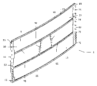
FIG. 1 illustrates a perspective view of one embodiment of the present
invention showing a
panel 1 having plate 5. As depicted in FIG. 1, the plate 5 of the panel 1 has
an outer surface 10,
a top edge 20, and a bottom edge 25. The bottom edge 25 is adapted to be
disposed upon a
ground surface. The plate 5 is attached to a first flange 40 at the first edge
30 of the plate 5. The
plate 5 is attached to the second flange 60 at the opposing second edge 35 of
the plate 5. FIG. 1
depicts the outer face 50 (Attie first flange 40 and the outer face 70 of the
second flange 60.
FIG. 1 illustrates the first flange 40 having holes 55. In one embodiment of
the present
invention, the holes 55 are unevenly spaced, having a higher density of holes
55 toward the
bottom of the first flange 40. The second flange 60 has pegs 75. In one
embodiment, the pegs 75
extend in direction normal to the outer face 70 of the second flange 60 and
are adapted for
penetration of the holes 55. Similar to the holes 55 and in one embodiment of
the present
invention, the pegs 75 are unevenly spaced with a higher density of pegs
disposed at the bottom
of the second flange 60. The higher density of holes 55 and corresponding pegs
75 disposed
4
CA 02770899 2012-03-09
toward the bottom of the first and second flanges provides for and
accommodates more water to
be placed in the reservoir. The additional water places more pressure toward
the bottom of the
flanges and a higher density of holes and pegs stabilize the bottom portion of
the structure and
further secures the connection between interconnected panels. In many
embodiments of the
present invention, the pegs 75 are integrally formed with the second flange
60.
FIG. 1 illustrates crossbars 90 that are used to attach temporarily a panel
connector piece of a
front end loader or tele-handler for transportation. Thus, a front end loader
or tele-handler can
easily manipulate and transport a panel during reservoir frame construction.
In one embodiment,
the crossbars 90 may be attached to the outer surface 10 of the panel 1.
Additionally, FIG. 1
depicts horizontal support beams 95 to further secure and strengthen the panel
1 and plate 5. The
horizontal support beams 95 are generally parallel to the top edge 20 and the
bottom edge 25,
and the horizontal support beams are disposed between the first edge 30 and
opposing second
edge 35. In another embodiment the crossbars 90 may be attached to the
horizontal support
beams 95.
In one embodiment of the present invention the panels have a curvature such
that when
numerous panels are interconnected via the pegs 75 and holes 55, a generally
circular reservoir
frame system is constructed. The curvature is generally convex relative to the
outer surface and
concave relative to the inner surface.
In various embodiments of the present invention, the first flange 40 is
integrally formed with
the plate 5. Likewise, the second flange 60 is integrally formed with the
plate 5, in many
embodiments of the present invention.
FIG. 2 illustrates a front view of the top of the embodiment of the present
invention as
depicted in FIG. 1. FIG. 2 further depicts the pegs 75 and holes 55 having a
higher density of
5
CA 02770899 2012-03-09
both at the bottom portion of the flange. FIG. 2 shows one embodiment of the
present invention
wherein the pegs 75 and corresponding holes 55 have a larger diameter toward
the bottom
portion of the first flange 40 and the second flange 60. This further secures
connection between
panels because the lower, larger diameter pegs 75 have additional sheer
strength and are able to
accorrunodate greater pressures against the inner surface of the panel 1.
FIG. 3 depicts the inner surface 15 of the plate 5 of the panel 1 having a top
edge 20 and a
bottom edge 25. The plate 5 is attached to the first flange 40 at the first
edge 30. The plate 5 is
attached to the second flange 60 at the opposing second edge 35. FIG. 3
depicts the first flange
inner face 45 and the second flange inner face 65. FIG. 3 illustrates the
first flange 40 having
holes 55. The second flange 60 has pegs 75.
FIG. 4 depicts a perspective view of the outer surface of two panels prior to
connection of the
two panels. The pegs 75 of the second flange 60 of one panel will penetrate
the holes 55 of the
first flange 40 of another panel. In this representation of the present
invention the second flange
outer face 70 is aligned opposite the first flange inner face 45 (not
depicted).
FIG. 5 depicts a perspective view of the outer surface after the connection of
two panels. In
this representation, the outer face 75 of the second flange 60 contacts the
inner face (not
depicted) of the first flange 40. The pegs 75 penetrate the holes 55.
Furthermore, FIG. 5 depicts
pins 85 penetrating the pegs 75 in order to further secure the interlocking
panels.
FIG. 6 depicts a perspective view of the inner surface of two panels prior to
the interlocking
connection. FIG. 6 is the inside view of the invention shown in FIG. 4, i.e.,
prior to connection
of panels.
6
CA 02770899 2012-03-09
FIG. 7 depicts a perspective view of the inner surface after the connection of
two panels.
FIG. 7 depicts the inside view of the invention shown in FIG. 5, i.e., when
connection of the
panels occurs.
FIG. 8A depicts the pin 85 and the peg 75 with a cut out representation of the
eyelet 80 to
accommodate penetration of the pin 85. FIG. 8B more depicts the pin 85
penetrating the peg 75
through the eyelet as show previously in FIG. 8A. The pin 85 goes through the
peg 75 via the
eyelet 80 (not depicted). In one embodiment of the present invention, the
eyelet 80 is at an angle
of roughly 45 relative to the bottom edge 25.
FIG. 9 depicts a top perspective side view of panels fully connected and
creating a circular
reservoir frame of interlocking panels. The interlocking panels form a variety
of shapes in
various embodiments, including oval and circles.
FIG. 10 shows a liner 105 covering the inner surface of the reservoir frame
and the bottom of
the reservoir.
FIG. 11 illustrates a perspective view of one embodiment of the present
invention showing
panels having vertical support beams 150. Such vertical support beams further
secure and
support the reservoir panel 1 and plate 5 in order to hold and contain large
amounts of liquid in
the reservoir frame.
It is believed that the apparatus of the present invention and many of its
attendant advantages
will be understood from the foregoing description. It is also believed that it
will be apparent that
various changes may be made in the form, construction, and arrangement of the
components
without departing from the scope and spirit of the invention and without
sacrificing its material
advantages. The forms described are merely exemplary and explanatory
embodiments thereof.
It is the intention of the following claims to encompass and include such
changes.
7