Note: Descriptions are shown in the official language in which they were submitted.
CA 02770940 2012-03-05
Attorney Docket No.: 2010P03214US
1
DRAIN HOSE FOR A WASHER
CROSS-REFERENCE TO RELATED APPLICATIONS
[0001] This application is related to applicant's co-pending U.S. application,
which is
filed concurrently herewith, titled "DRAIN HOSE CLIP FOR A WASHER", Attorney
Docket
No. 2011P00378US, which is incorporated herein by reference in its entirety.
FIELD OF THE INVENTION
[0002] The present invention is directed to a drain hose for a household
appliance, and a
household appliance having a drain hose, and more particularly, to a drain
hose having a flex-
section having a plurality of repeating cross-sectional profiles, wherein each
profile includes a
ridge and a trough.
BACKGROUND OF THE INVENTION
[0003] A household appliance, such as a front-loading clothes washer, includes
a housing
supported by a structure, such as a floor. A door provides access to a washing
unit in the interior
of the appliance housing. The washing unit includes a tub having a cylindrical
washing drum
rotatably mounted inside the tub. In operation, clothes or laundry are
inserted into the washer
through the door and placed in the rotating washing drum inside the tub. The
household
appliance wets the laundry to be washed with washing liquid and mechanically
moves the
CA 02770940 2012-03-05
Attorney Docket No.: 201 OP03214US
2
laundry to release contaminants from the laundry. A drive system rotates the
washing drum
inside the tub about an axis of the drum.
[0004] The washer can remove dirt from laundry with washing, rinsing, and
spinning
cycles using detergent and water. The washer commonly includes a drain pump
for pumping out
washing or rinsing liquid from the tub to an exterior (e.g., an external drain
facility), and a drain
hose that connects the drain pump and the external drain facility, such as a
drain pipe, for
discharging the washing or rinsing liquid pumped by the drain pump to the
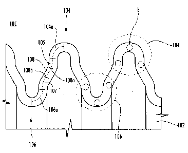
exterior.
[0005] In the past, conventional drain hose assemblies commonly have included
two
individual drain hoses, one plastic connector, and two hose clamps. These
conventional systems
commonly require pre-assembly of an internal (first) drain hose to a first
side of a plastic
connector with a first metal clamp before the drain hose is installed in the
washer. The
installation of such a conventional drain hose assembly can be burdensome,
time consuming, and
costly. Additionally, with the conventional drain hose assembly, the user of
the washer
commonly will have to install an external (second) drain hose to the other
side (second side) of
the plastic connector with a second metal clamp prior to using the washer.
[0006] Recently, a continuous one-piece drain' hose has been provided to
reduce the total
number of components in the draining system, thereby reducing or minimizing
costs and
assembly time. A one-piece drain hose may simplify the installation of the
drain hose by the
manufacturer, thereby reducing the labor, time, and expense associated with
the drain hose,
while also reducing the time and effort on the part of the user to connect the
drain hose to a drain
pipe when installing the washer.
CA 02770940 2012-03-05
Attorney Docket No.: 201 OP03214US
3
[0007] During the assembly process of the washer, a first open end of the
drain hose is
coupled to the housing of the drain pump inside the washer housing. The
continuous drain hose
may then be inserted through an opening in the rear panel of the washer
housing to the exterior
of the washer. In this manner, when the washer is being installed by the
consumer, the drain
hose is already coupled to the drain pump of the washer and the user simply
positions the second
open end (distal end) of the hose into an external drain pipe.
[0008] In order to connect the drain hose to the drain pump inside the washer
and then
extend the drain hose through the rear panel of the washer to the exterior,
the drain hose
commonly must be routed through open areas inside of the washer and then bent
in an arch shape
in order to route the drain hose from inside the housing and through an
opening in the rear panel
of the washer housing to the exterior. The internal clearance within the
housing of the washer
for routing the drain hose may be limited or restricted depending on the
arrangement of the drain
pump, drain hose, and other components of the washer. Thus, one or more
portions of the drain
hose commonly must be bent by, for example, 90 - 180 degrees from its original
straight shape.
[0009] Additionally, the packaging materials used to protect and ship the
washer from
the manufacturer to the customer may provide limited or restricted clearance
on the outside of
the washer housing for routing the portion of the drain hose that extends from
the rear panel of
the washer housing. Thus, another portion of the drain hose that is outside of
the housing of the
washer commonly must be bent in an arch shape by, for example, 90 - 180
degrees from its
original straight shape in order to avoid interference with the packing
materials used to protect
and transport the washer from the manufacturer to the customer.
CA 02770940 2012-03-05
Attorney Docket No.: 2010P03214US
4,
[0010] In order to facilitate the bending of the drain hose, the conventional
continuous
drain hose commonly is formed from a corrugated plastic hose pattern having a
wave pattern or a
spiral pattern that may be formed by casting or molding. For example, as
illustrated in FIG. 1,
the conventional drain hose commonly includes a corrugated hose 10 having a
plurality of rings
12 formed by a repeating profile of ridges 14 and troughs 16. The profiles
commonly may
include a flat ridge 14 and a U-shaped trough 16, or triangular shaped ridges
and troughs.
[0011] As schematically illustrated in FIG. 2, when a conventional drain hose
is flexed or
bent in an arch shape, for example by 90 ... 180 degrees, one side of the
plastic drain hose 10
expands or stretches, while the other side is compressed or crushed, thereby
exposing portions of
the drain hose to different amounts of stress and strain. For example, as
shown in FIG. 2, the
portions of the drain hose that are exposed to higher degrees of crushing and
expansion typically
are exposed to a greater amount of stress (e.g., S1, S2) than other areas
(e.g., S3, S4, S5).
Such high stress areas may be susceptible or more prone to failure or leaking,
for example, over
time.
SUMMARY OF THE INVENTION
[0012] The present invention recognizes that, during bending, in addition to
the amount
of stress on the drain hose varying based on the amount of crushing or
expansion, the amount of
stress acting on portions of the drain hose varies based on the profile of the
rings of the
corrugated section of the drain hose. More particularly, the amount of stress
may be different for
different portions of each profile of the rings.
CA 02770940 2012-03-05
Attorney Docket No.: 201 OP03214US
[0013] For example, an amount of stress commonly is greater in areas of the
profile
where bending occurs, such as in the lowermost area of each trough 16 and the
uppermost area of
each ridge 14 in FIG. 1. As a result, the conventional drain hose may exhibit
white stretch marks
on each corrugated ring 12 at the section of the hose 10 that is bent. These
white stretch marks
correspond to locations of stretching/expansion and compressing/crushing, and
are an indication
of high stress on the material at these areas. Such high stress areas may be'
susceptible or more
prone to failure or leaking, for example, over time.
[0014] With reference to FIG. 3, the conventional drain hose 10 may include,
for
example, a flat ridge 14 and a U-shaped trough 16. The ridge 16 has two
bending points b,
which are schematically identified by black dots. The trough 16 has a single
bending point b,
which is similarly identified by a black dot in FIG. 3. The stress resulting
from bending the drain
hose, for example 90180 degrees, is concentrated at these bending points b,
which may lead to
large amounts of stress at these locations and in some cases cracking or
tearing of the drain hose.
[0015] The present invention also recognizes that routing the drain hose and
flexing or
bending the drain hose during the installation process may result in the drain
hose being twisted
or otherwise disoriented such that the drain hose is not oriented in a proper
position for
installation into a drain pipe by the consumer.
[0016] These problems and others are addressed by the present invention, a
first
exemplary embodiment of which comprises a drain hose for a washer, the drain
hose comprising
a first open end, a second open end, a continuous portion extending from the
first open end to the
second open end, wherein the continuous portion includes a first bending
portion having a
CA 02770940 2012-03-05
Attorney Docket No.: 201 OP03214US
6
plurality of repeating profiles, wherein a cross-section of each profile
includes a ridge and a
trough, and wherein one of the ridge has at least three predetermined bending
points and the
trough has at least two predetermined bending points.
[0017] In an exemplary embodiment, the ridge has at least three predetermined
bending
points and the trough has at least two predetermined bending points. In other
embodiments, each
of the ridge and the trough has at least three predetermined bending points.
[0018] The cross-section of each profile can include a leg portion connecting
the ridge
and trough, wherein a first end of the leg portion is connected to the ridge
by a first radius
portion, and wherein a second end of the leg portion is connected to the
trough by a second
radius portion. More particularly, the ridge can include a first curved
portion and the trough can
include a second curved portion, wherein the cross-section of each profile
further includes a
tangential portion connecting the first curved portion to the second curved
portion, a first radius
transitioning from the first curved portion to a first end of the tangential
portion, and a second
radius transitioning from the second curved portion to a second end of the
tangential portion.
[0019] The continuous portion of the drain hose can include a second bending
portion
having a plurality of second repeating portions, which may be similar to the
repeating portions of
the first bending portion. The continuous portion can include a straight
portion coupling the first
bending portion to the second bending portion. The straight portion can
include a mating surface
for receiving a drain hose clip that secures the drain hose to the household
appliance. The
straight portion also can include one or more alignment elements, such as one
or more
projections extending from a surface of the straight portion, wherein the one
or more alignment
CA 02770940 2012-03-05
Attorney Docket No.: 201 OP03214US
7
elements provides a predetermined orientation of the drain hose with respect
to a drain hose clip
that is coupled to the household appliance. The one or more alignment elements
can engage with
the clip only one way, thereby ensuring a proper alignment and orientation of
the drain hose with
the clip.
[0020] The drain hose can include a first corrugated portion disposed on an
opposite side
of the first bending portion from the straight portion and between the first
bending portion and
the first open end, and a second corrugated portion disposed on an opposite
side of the second
bending portion from the straight portion and between the second bending
portion and the second
open end. The first open end or the second open end can have a pump alignment
element for
engaging a corresponding pump alignment feature of a pump housing.
[0021] In an embodiment, the household appliance is a washer having a drain
pump
including a pump housing.
[0022] Another exemplary embodiment of the invention comprises a household
appliance, such as a washer, including a housing having a front wall and a
rear panel, the housing
having a door formed in the front wall for accessing an interior of the
housing, a tub disposed
inside the housing, a rotatable drum within the tub and having an axis of
rotation, the rotatable
drum for receiving laundry through the door, a drain pump disposed inside the
housing, and a
drain hose including a first open end, a second open end, a continuous portion
extending from
the first open end to the second open end, wherein the continuous portion
includes a first bending
portion having a plurality of repeating profiles, wherein a cross-section of
each profile includes a
CA 02770940 2012-03-05
Attorney Docket No.: 201 OP03214US
8
ridge and a trough, and wherein one of the ridge has at least three
predetermined bending points,
and the trough has at least two predetermined bending points.
[0023] In this embodiment, the first open end of the drain hose is coupled to
the pump
housing and the second open end of the drain hose is disposed outside of the
housing.
[0024] The housing includes an opening in the rear panel, and the drain hose
extends
through the opening. In an assembled state, the first bending portion can be
disposed adjacent to
the rear panel of the housing and inside the housing, and the second bending
portion can be
disposed adjacent to the rear panel of the housing and outside the housing.
The straight portion
can be disposed in the opening of the rear panel.
[0025] In an embodiment, the opening forms a fitting support, and the
household
appliance comprises a clip secured to the fitting support. The straight
portion can include a
mating surface engaging the clip to secure the drain hose to the fitting
support of the rear panel.
For example, the clip can include a first alignment element and the straight
portion of the drain
hose can include a second alignment element, such that the first alignment
element of the clip
engages the second alignment element of the drain hose to provide a
predetermined orientation
of the drain hose with respect to the clip.
[0026] In this manner, the exemplary embodiments of the drain hose can
distribute stress
applied to the drain hose during bending, for example of 90 - 180 degrees,
over a larger number
of bending points, thereby reducing or minimizing an amount of stress at each
bending point, and
reducing, minimizing, or eliminating the potential for failure or leaking, for
example, over time.
The exemplary embodiments dramatically reduce the stress and strain on the
ridge and trough of
CA 02770940 2012-03-05
Attorney Docket No.: 201 OP03214US
9
each profile as compared to the stress on the conventional drain hose.
Additionally, the
exemplary embodiments can reduce the stress and strain on the areas that are
exposed to higher
degrees of crushing and expansion, as compared to the stress on the
conventional drain hose, as
shown in FIG. 2.
[0027] The exemplary embodiments of the drain hose can include one or more
flex
portions having greater flexibility than other portions (e.g., normal
corrugated portions) of the
drain hose. In this manner, a portion of the drain hose that is positioned
adjacent to the opening
in the rear panel of the housing can have a greater flexibility than a
remaining portion of the
drain hose, which may be less flexible while still maintaining sufficient or
acceptable flow
through the drain hose. In an embodiment, only the portion of the drain hose
that is adjacent the
rear panel of the housing includes a portion which has a higher degree of
flexibility, thereby
permitting the drain hose to be bent substantially 90. 180 degrees at this
location without
damaging the drain hose.
[0028] The exemplary drain hose includes a corrugated pattern having a
predetermined
profile that provides greater flexibility at a portion intended for a higher
degree of bending than
for portions where a lesser degree of bending is needed to position the hose
in the washer. For
purposes of this disclosure, the portion having such a predetermined profile
for providing greater
flexibility will be referred to as a "flex section." The area of lesser degree
of bending can have a
profile similar to the conventional corrugated profile shown in FIG. 1, and
will be referred to as a
"normal corrugation section."
CA 02770940 2012-03-05
Attorney Docket No.: 201 OP03214US
[0029] The exemplary embodiments of the drain hose having the flex section can
reduce
bending stress on each point and also increase the flexibility of this portion
of the drain hose,
such that the flex section of the drain hose can be bent by about 90 degrees
or more while
minimizing or eliminating a risk of damaging the drain hose, such as creating
a crack/tear.
[0030] The exemplary embodiments also can provide a continuous, one-piece
drain hose
having a double-flex feature which can improve flexibility and save space
inside the washer and
outside the washer for providing sufficient clearance for product packaging.
In this manner, a
flex section can be located on both the inside and outside connection points
to the drain hose clip
for coupling the drain hose to an opening in the rear panel of the washer
housing. By providing a
drain hose having a flex-section, or a double-flex section, the drain hose
according to the
exemplary embodiments can be assembled in an area inside the housing of washer
having limited
space. The drain hose according to the exemplary embodiments also enables the
drain hose to be
routed on the outside of the rear panel of the washer housing within a limited
space between the
rear panel and the packaging for shipping the washer.
[0031] The double-flex section of the drain hose can include a straight
section (i.e., non-
bendable or low flexibility section) interposed between two flex sections. In
this manner, the
straight section can engage and be coupled to a drain hose clip or the like
for securing the drain
hose to the opening in the rear panel of the washer housing.
[0032] The straight section can include one or more orientation features for
ensuring a
correct orientation of the drain hose with respect to a drain hose clip or the
like for securing the
drain hose to the opening in the rear panel of the washer housing. For
example, the straight
CA 02770940 2012-03-05
Attorney Docket No.: 201 OP03214US
11
section can include two orientation features for engaging corresponding
orientation features on a
drain hose clip, thereby ensuring a correct orientation of the drain hose with
respect to a drain
hose clip. The orientation features can be different such that there is only a
single way to
connect the drain hose clip to the drain hose, thereby further ensuring that
the drain hose clip is
properly orientated with respect to the drain hose and the rear panel of the
washer housing.
[0033] The drain hose includes a first open end for coupling to a housing of a
drain pump
inside the washer. The pump housing can include a fitting having an
orientation feature, such as
a key, tab, projection, or the like. The first open end of the drain hose can
include a
corresponding orientation feature, such as a ring portion having an opening
section that engages
the orientation feature of the pump housing. The corresponding orientation
features can ensure
that the drain hose is installed in the correction orientation to avoid or
prevent twisting of the
drain hose when the drain hose is coupled to the rear panel of the appliance
by, for example, a
drain hose clip or the like in an assembled state.
[0034] An exemplary method of installing the drain hose can include a step of
feeding
the drain hose from the outside of the washer through an opening or cutout on
the rear panel of
the appliance. Next, a drain hose clip can be coupled to the drain hose, for
example by snap-
fitting the drain hose clip to the drain hose at the straight portion of the
drain hose. The
orientation features on the drain hose clip and the drain hose can ensure that
the drain hose will
be oriented properly for correct installation on the pump housing of the drain
pump. The drain
hose clip is then aligned with the cutout or opening in the rear panel of the
housing and pushed
into the opening in the housing until the drain hose clip snaps and locks in
place. The drain hose
CA 02770940 2012-03-05
Attorney Docket No.: 201 OP03214US
12
clip can be configured to be inserted into the opening in the housing, for
example, from the
interior side of the housing or the exterior side of the housing, or in other
embodiments, from
both the interior and exterior side of the housing, for example, if the drain
hose clip is formed
from separate pieces. The first open end of the drain hose is then coupled to
the housing of the
drain pump. As explained above, the corresponding orientation features of the
drain hose and the
pump fitting can further ensure that the drain hose is correctly aligned to
avoid twisting of the
drain hose. The drain hose can then be secured to 'the inside of the rear
panel of the housing
using, for example, a side panel clip. Next, the drain hose can be routed and
secured to the rear
panel of the housing at a second location using another hose clip or hose
support. The drain hose
can remain in this secured state during packaging and shipping to prevent
damage to the drain
hose. After the washer is delivered to a user and the packaging is removed,
the user simply can
remove the hose from the second hose clip or support and position the second
open end (distal
end) of the hose into an external drain pipe to complete the installation of
the drain hose.
[0035] The exemplary embodiments also can provide a continuous, one-piece
drain hose
and fitting support assembly that ensures that the first open end of the drain
hose is properly
aligned and oriented with the drain pump in the washer, while also ensuring
that the drain hose is
properly aligned and oriented with the fitting support, and properly aligned
and oriented for
insertion into a drain pipe located exterior to the washer.
[0036] The exemplary embodiments of the drain hose and the drain hose clip can
control
the orientation of the drain hose and the drain hose clip with respect to each
other, as well as to
the opening in the rear panel of the washer housing. The drain hose clip also
can reduce or
CA 02770940 2012-03-05
Attorney Docket No.: 2010P03214US
13
prevent movement of the drain hose into and out of the opening in the rear
panel of the washer
housing, thereby reducing or preventing damage from the drain hose rubbing
against the housing
or the opening of the housing.
[0037] Other features and advantages of the present invention will become
apparent to
those skilled in the art upon review of the following detailed description and
drawings.
BRIEF DESCRIPTION OF THE DRAWINGS
[0038] These and other aspects and features of embodiments of the present
invention will
be better understood after a reading of the following detailed description,
together with the
attached drawings, wherein:
FIG. 1 is a side, cross-sectional view of a conventional drain hose.
FIG. 2 is a schematic illustration of bending stress in a conventional drain
hose.
FIG. 3 is a partial side, cross-sectional view of a normal corrugated section
of the
conventional drain hose of FIG. 1.
FIG. 4A is a schematic side view of a drain hose according to an exemplary
embodiment
of the invention.
FIG. 4B is a partial side view of a drain hose of the drain hose of FIG. 4A.
FIG. 4C is a partial side, cross-sectional view of a flex-section of the drain
hose of FIG.
4A.
FIG. 4D is a partial side, cross-sectional view of a normal corrugated section
of the drain
hose of FIG. 4A.
CA 02770940 2012-03-05
Attorney Docket No.: 201 OP03214US
14;
FIG. 5 is a side, cross-sectional view of a drain hose according to an
exemplary
embodiment of the invention.
FIG. 6 is an enlargement of a partial side, cross-sectional view of a profile
of the drain
hose of FIG. 5.
FIG. 7 is a partial perspective view of a drain hose according to an exemplary
embodiment of the invention.
FIG. 8A is a partial perspective view of a drain hose clip and a drain hose
according to an
exemplary embodiment of the invention.
FIG. 8B is another partial perspective view of a drain hose clip and a drain
hose
according to an exemplary embodiment of the invention.
FIG. 9A is a partial perspective assembly view of a rear panel of a washer
housing and a
drain hose according to an exemplary embodiment of the invention.
FIG. 9B is another partial perspective assembly view of a drain hose clip and
drain hose
according to an exemplary embodiment of the invention.
FIG. 9C is a partial perspective assembly view of a rear panel of a washer
housing and an
assembled drain hose clip and drain hose according to an exemplary embodiment
of the
invention.
FIG. 10 is a partial perspective view of an interior of a rear panel of a
washer housing and
an assembled drain hose clip and drain hose according to an exemplary
embodiment of the
invention.
CA 02770940 2012-03-05
Attorney Docket No.: 201OP03214US
FIG. 11 is a partial side view of an exterior of a rear panel of a washer
housing and a
drain hose according to an exemplary embodiment of the invention.
FIG. 12 is another partial perspective view of an interior of a rear panel of
a washer
housing and an assembled drain hose clip and drain hose according to an
exemplary embodiment
of the invention.
FIG. 13 is another partial perspective view of an exterior of a rear panel of
a washer
housing and an assembled drain hose clip and drain hose according to an
exemplary embodiment
of the invention.
FIG. 14 is another partial perspective view of an interior of a rear panel of
a washer
housing and an assembled drain hose clip and drain hose according to an
exemplary embodiment
of the invention.
FIG. 15 is another partial perspective view of an exterior of a rear panel of
a washer
housing and an assembled drain hose clip and drain hose according to an
exemplary embodiment
of the invention.
FIG. 16A is a perspective view of a drain pump of a washer and a first open
end of the
drain hose according to an exemplary embodiment of the invention.
FIG. 16B is a side view of a drain pump of a washer and a first open end of
the drain hose
according to an exemplary embodiment of the invention.
FIG. 17 is schematic front view of a washer according to an exemplary
embodiment of
the invention.
CA 02770940 2012-03-05
Attorney Docket No.: 2010P03214US
16
DETAILED DESCRIPTION OF THE EXEMPLARY EMBODIMENTS OF THE INVENTION
[0039] The present invention now is described more fully hereinafter with
reference to
the accompanying drawings, in which embodiments of the invention are shown.
This invention
may, however, be embodied in many different forms and should not be construed
as limited to
the embodiments set forth herein; rather, these embodiments are provided so
that this disclosure
will be thorough and complete, and will fully convey the scope of the
invention to those skilled
in the art.
[0040] Referring now to the drawings, FIGS. 4 - 17 illustrate exemplary
embodiments of
a drain hose and a household appliance, such as a washer, having a drain hose.
[0041] An exemplary embodiment of a continuous, one-piece drain hose 100 will
now be
described with reference to FIGS. 4A - 6.
[0042] As shown in FIGS. 4A - 4D, an exemplary embodiment of the drain hose
100 can
include a first open end 115, a second open end 117, a continuous portion
extending from the
first open end 115 to the second open end 117. The continuous portion can
include a continuous,
one-piece construction having a flex section (e.g., double-flex section 112)
which can improve
flexibility and save space inside the washer and outside the washer for
providing sufficient
clearance for product packaging. The drain hose 1 00 can include normal
corrugation sections
(e.g., 114, 116) between the double flex-section 112 and the open ends 115,
117 of the drain hose
100, as shown for example in FIG. 4D.
[0043] The first open end 115 of the drain hose 100 can be configured for
coupling to a
pump housing of a drain pump inside the washer (described in greater detail
below with
CA 02770940 2012-03-05
Attorney Docket No.: 201 OP03214US
17.
reference to FIGS. 16A and 16B). For example, the first open end 115 of the
drain hose 100 can
include an orientation feature, such as a ring portion 120, that engages a
corresponding
orientation feature of the pump housing, thereby ensuring that the drain hose
100 is installed in
the correction orientation to avoid or prevent twisting of the drain hose 100
when the drain hose
100 is coupled to the rear panel of an appliance in an assembled state. The
second open end 117
can be configured for insertion into, or coupling with, an external drain pipe
(not shown).
[0044] As exemplarily illustrated in FIGS. 4A, 4B, and 4C, the double-flex
section 112
can include a first flex section 112A having a plurality of first repeating
profiles, wherein a
cross-section of each profile includes a ridge 104 and a trough 106 (described
in more detail with
reference to FIGS. 5 and 6), and wherein the ridge 104 has at least three
predetermined bending
points and/or the trough 106 has at least two predetermined bending points.
The double-flex
section 112 of the drain hose 100 also can include a second flex section 112B
having a plurality
of second repeating profiles, which may be similar to the repeating profiles
of the first flex
section 112A. Alternatively, the second flex section 112B can include a
plurality of second
repeating profiles that are different from the first repeating profiles of the
first flex section 112A.
[0045] In an exemplary embodiment, the double-flex section 112 of the drain
hose also
can include a straight section 113 (i.e., a non-bendable or low flexibility
section, or non-
corrugated section) interposed between the two flex sections 112A, 112B. The
straight portion
113 can include a mating surface (e.g., a smooth cylindrical surface) for
receiving a drain hose
clip (e.g., 300; described in greater detail with reference to FIGS. 7-15) to
secure the drain hose
100 to a household appliance.
CA 02770940 2012-03-05
Attorney Docket No.: 201 OP03214US
18
[0046] The drain hose 100 can include one or more additional straight sections
(i.e., non-
corrugated sections), such as a straight section 119 illustrated in FIG. 4A.
In the exemplary
embodiment of FIG. 4A, another section 118 having a normal corrugation profile
(e.g., similar to
the profile of FIG. 4D) can separate the straight section 119 from the ring
portion 120 of the first
open end 115, thereby providing flexibility for positioning and coupling the
first open end 115 of
the drain hose 100 to a pump housing of a drain pump inside the washer. In
another
embodiment, the section 118 can be formed from a plurality of repeating rings
similar to those of
the flex-sections 112A, 112B (shown in FIG. 4C), thereby providing greater
flexibility and ease
with which the drain hose 100 can be coupled to,the drain pump.
[0047] With reference to FIGS. 5 and 6, an exemplary embodiment of the double-
flex
section 112, including one or more flex-sections 112A, 112B having a plurality
of repeating
rings 102, will now be described. As shown in FIGS. 5 and 6, each of the rings
102 can include
a cross-section having a predetermined profile including a ridge 104 and
trough 106. The ridge
104 has three or more predetermined bending points B. Alternatively, the
trough 106 has two or
more predetermined bending points B. In other embodiments, the ridge 104 has
three or more
predetermined bending points B and the trough 106 has two or more
predetermined bending
points B. In other embodiments, each of the ridge 104 and the trough 106 has
three or more
predetermined bending points B.
[0048] As shown by the dashed lines in FIG. 6, the ridge 104 and trough 106
can be
connected by a tangential leg portion 108 that is connected between the ridge
104 and the trough
106 by radius portions 105, 107. More particularly, the ridge 104 can include
a first curved
CA 02770940 2012-03-05
Attorney Docket No.: 201 OP03214US
19
portion 104a and the trough 106 can include a second curved portion 106a,
wherein the cross-
section of each profile further includes a tangential portion 108 connecting
the first curved
portion 104a to the second curved portion 106a, a first radius 105
transitioning from the first
curved portion 104a to a first end 108a of the tangential portion 108, and a
second radius 107
transitioning from the second curved portion 106a to a second end 108b of the
tangential portion
108.
[0049] In comparison, with reference again to FIG. 3, the conventional art
drain hose 10
includes a ridge 14 having only two bending points b and a trough 16 having
only a single
bending point b.
[0050] In this manner, the exemplary embodiments of the drain hose 100 can
distribute
stress applied to the drain hose 100 during bending, for example of 90 - 180
degrees, over a
larger number of bending points B, thereby reducing or minimizing an amount of
stress at each
bending point, and reducing, minimizing, or eliminating the potential for
failure or leaking, for
example, over time. The exemplary embodiments dramatically reduce the stress
and strain on
the ridge 104 and trough 106 of each profile as compared to the stress on the
conventional drain
hose 10, as shown for example in FIG. 2. Additionally, the exemplary
embodiments can reduce
the stress and strain on the areas that are exposed to higher degrees of
crushing and expansion, as
compared to the stress on the conventional drain hose, as shown in FIG. 2. The
flex-sections
112A, 112B can provide greater flexibility than other portions (e.g., normal
corrugated portions
114, 116) of the drain hose 100. In this manner, a portion of the drain hose
100 that is positioned
adjacent to an opening in the rear panel of an appliance housing can have a
greater flexibility
CA 02770940 2012-03-05
Attorney Docket No.: 201 OP03214US
20.
(e.g., is easier to bend, bends further, etc. without damaging the drain hose
100) than a remaining
portion of the drain hose 100, which may be less flexible while still
maintaining sufficient or
acceptable flow through the drain hose 100.
[0051] In an embodiment, only a portion of the drain hose 100 that is adjacent
to the rear
panel of the housing includes a portion (e.g., flex-sections 112A, 112B) which
has a higher
degree of flexibility, thereby permitting the drain hose 100 to be easily bent
substantially 90
180 degrees (or more) at this location without damaging the drain hose 100. In
this embodiment,
the remaining portions of the drain hose 100 can be formed, for example, from
one or more
normal corrugation sections (e.g., 114, 116) or one or more straight sections
(e.g., 113, 119).
[0052] With reference to the exemplary embodiment of FIGS. 7 - 9C, the
straight section
113 of the drain hose 100 can include one or more alignment or orientation
features 124, 126 for
ensuring a correct orientation of the drain hose 100 with respect to a drain
hose clip 300 or the
like for securing the drain hose 100 to an opening in a rear panel 406 of the
washer housing. For
example, the straight section 113 can include two orientation features 124,
126 for engaging
corresponding orientation features 304, 306 on a drain hose clip 300, thereby
ensuring a correct
orientation of the drain hose 100 with respect to a drain hose clip 300. The
orientation features
124, 126 can be different such that there is only a single way to connect the
drain hose clip 300
to the drain hose 100, thereby further ensuring that the drain hose clip 300
is properly orientated
with respect to the drain hose 100 and the rear panel 406 of the washer
housing. In an exemplary
embodiment, one of the orientation features 124, 126 can include a raised
projection or disc
portion that extends away from the surface of the straight section 113 and
extends partially
CA 02770940 2012-03-05
Attorney Docket No.: 2010P03214US
21
around a circumference of the straight portion 113. One of ordinary skill in
the art will recognize
that the orientation features are not limited to the illustrated exemplary
embodiments and one or
more orientation features can be provided on the drain hose 100 or the drain
hose clip 300. The
orientation features can be projections or the like that extend from the
surface of either the drain
hose 100 or the drain hose clip 300, or grooves, channels, or the like that
are recessed into the
surface of either the drain hose 100 or the drain hose clip 300, or
combinations thereof.
[0053] In this manner, the straight section 113 can engage and be coupled to a
drain hose
clip (e.g., 300 shown in FIGS. 8A and 8B) or the like for securing the drain
hose 100 to an
opening or fitting support 408 in the rear panel (e.g., 406 shown in FIGS. 9A
and 9C) of the
washer housing. In FIGS. 9A and 9C, the rear panel is illustrated as being
transparent for
illustrative and clarification purposes only, such that the arrangement of the
drain hose 100 is
visible.
[0054] In operation, the first open end 115 of the drain hose 100 can be
coupled to the
housing 202 of the drain pump 200 (as described in more detail below with
reference to FIGS.
16A and 16B). The exemplary drain hose 100 can be installed through an opening
408 in the
rear panel 406 of the washer housing such that a portion of the drain hose 100
extends outside
the housing of the washer. Next, the drain hose clip 300 can be coupled to the
straight portion
113 of the drain hose 100.
[0055] To simplify the installation of the drain hose 100 into the drain hose
clip 300 after
the drain hose 100 is inserted into the opening 408 in the rear panel 406 of
the washer housing,
an exemplary embodiment of the drain hose clip 300 can include a first portion
302A and a
CA 02770940 2012-03-05
Attorney Docket No.: 2010P03214US
22
second portion 302B that engage each other to form the drain hose clip 300.
For example, the
first portion 302A and second portion 302B can be coupled around (e.g.,
wrapped around) the
drain hose 100 without having to insert the length of the drain hose 100
through the drain hose
clip 300. The first portion 302A and second portion 302B can be separate
parts, or the first
portion 302A and second portion 302B can be moveably coupled together. For
example, the
drain hose clip 300 can include a connecting strip 308, or other suitable
feature for moveably
connecting the first portion 302A and second portion 302B, such as a hinge or
the like, for
coupling the first portion 302A to the second portion 302B while permitting
movement of these
portions with respect to each other. In this manner, the first portion 302A
and the second portion
302B of the drain hose clip 300 can be slid onto (e.g., around) the drain hose
100, for example
from below, while the drain hose 100 is already inserted into the opening 408
in the rear panel
406 of the housing. Next, the drain hose clip 300 can be coupled to the drain
hose 100, for
example by snap-fitting the first portion 302A to the second portion 302B
around the drain hose
100 in a direction dl at the straight portion 113 of the drain hose 100, as
illustrated in FIG. 9B.
[0056] The orientation features 304, 306 on the drain hose clip 300 and the
corresponding orientation features 124, 126 on the drain hose 100 can ensure
that the drain hose
100 will be oriented properly for correct installation of one end of the drain
hose 100 on the
pump housing 202 of the drain pump 200, or for insertion of the other end of
the drain hose 100
into an external drain pipe located adjacent of the washer. The orientation
features can be
arranged such that the drain hose 100 can be coupled to the drain hose clip
300 in only a single
way. One of ordinary skill in the art will recognize that the orientation
features are not limited to
CA 02770940 2012-03-05
Attorney Docket No.: 201 OP03214US
23
the illustrated exemplary embodiments and one or more orientation features can
be provided on
the drain hose 100 or the drain hose clip 300.
[0057] Next, the drain hose clip 300 is aligned with the cutout or opening 408
in the rear
panel 406 of the housing and pushed into the opening 408 in the housing until
the drain hose clip
300 snaps and locks in place, as illustrated in FIG. 9C. The drain hose clip
can be configured to
be inserted into the opening in the housing, for example, from the interior
side of the housing or
from the exterior side of the housing, or in other embodiments, from both the
interior and
exterior side of the housing, for example, if the drain hose clip is formed
from separate pieces.
[0058] With reference to FIGS. 10 - 13, the drain hose 100 can be bent
substantially
90-180 degrees (or more) at the flex-sections 112A, 112B such that the drain
hose 100 extends
along the inside and outside of the rear panel 406 of the housing. By
providing a drain hose 100
having a flex-section, or a double-flex section 112, the drain hose 100
according to the
exemplary embodiments can be assembled in an area inside the housing of washer
having limited
space (e.g., clearance Cl). The drain hose 100 according to the exemplary
embodiments enables
the drain hose 100 to be routed on the outside of the rear panel 406 of the
washer housing within
a limited space (e.g., clearance C2) between the rear panel 406 and the
packaging 500 for
shipping the washer. In FIGS. 12, 13, and 14, the rear panel is illustrated as
being transparent for
illustrative and clarification purposes only, such that the arrangement of the
drain hose 100 is
visible.
[0059] As shown in FIG. 14, the drain hose 100 can then be secured to the
inside of the
rear panel 406 of the housing using, for example, a side panel clip 602 or the
like. Next, the
CA 02770940 2012-03-05
Attorney Docket No.: 2010P03214US
24
drain hose 100 can be routed and secured to the rear panel 406 of the housing
at a second
location using another hose clip or hose support 604 or the like, as shown in
FIG. 15. The drain
hose 100 can remain in this secured state during packaging and shipping to
prevent damage to
the drain hose 100. After the washer is delivered to a user and the packaging
is removed, the
user simply can remove the second open end 117 of the drain hose 100 from the
second hose clip
or support 604 and position the second open end 117 (distal end) of the drain
hose 100 into an
external drain pipe (not shown) to complete the installation of the drain hose
100.
[0060] With reference to FIGS. 16A and 16B, the drain hose 100 can include a
first open
end 115 for coupling to a pump housing 202 of a drain pump 200 inside the
washer. The pump
housing 202 can include a fitting having an orientation feature 204, such as a
key, tab, projection,
or the like. The first open end 115 of the drain hose 100 can include a
corresponding orientation
feature, such as a ring portion 120 having an opening section 122 that engages
the orientation
feature 204 of the pump housing 202. The corresponding orientation features
120, 122 and 204
can ensure that the drain hose 100 is installed in the correction orientation
to avoid or prevent
twisting of the drain hose 100 when the drain hose 100 is coupled to the rear
panel of an
appliance by, for example, a drain hose clip 300 or the like in an assembled
state. One of
ordinary skill in the art will recognize that the orientation features are not
limited to the
illustrated exemplary embodiments and one or more orientation features can be
provided on the
drain hose 100 or the fitting of the housing 202, the drain pump 200, etc.
[0061] The drain hose 100 can include one or more additional straight sections
(i.e., non-
corrugated sections), such as straight section 119 shown in FIG. 16A. Another
section 118
CA 02770940 2012-03-05
Attorney Docket No.: 201 OP03214US
having a normal corrugation profile can separate the straight section 119 from
the ring portion
120 of the first open end 115, thereby providing flexibility for positioning
and coupling the first
open end 115 of the drain hose 100 to the pump housing 202 of the drain pump
200 inside the
washer. In another embodiment, the section 118 can be formed from a plurality
of repeating
rings similar to those of the flex-sections 112A, 112B, thereby providing
greater flexibility and
ease with which the drain hose 100 can be coupled to the pump housing 202 of
the drain pump
200 inside the washer.
[0062] As shown in FIG. 17, the appliance can be a washer, such as a front
load washer
400, having a housing 402 and a door 404 for accessing a rotatable drum that
is rotatably
mounted in a tub (not shown) within the housing 404.
[0063] The exemplary embodiments of the drain hose 100 and the drain hose clip
(i.e.,
drain hose clip) 300 can control the orientation of'the drain hose 100 and the
drain hose clip 300
with respect to each other, as well as to the opening 408 in the rear panel
406 of the washer
housing. The drain hose clip 300 also can reduce or prevent movement of the
drain hose 100
into and out of the opening 408 in the rear panel 406 of the washer housing
402, thereby
reducing or preventing damage from the drain hose 100 rubbing against the rear
panel 406 or the
opening 408 of the rear panel 406 of the housing 402.
[0064] The present invention has been described herein in terms of several
exemplary
embodiments. However, modifications and additions to these embodiments will
become
apparent to those of ordinary skill in the art upon a reading of the foregoing
description and
could be made without departing from the scope of the invention.