Note: Descriptions are shown in the official language in which they were submitted.
CA 02770993 2012-02-13
WO 2011/021827 PCT/KR2010/005411
1
Description
Title of Invention: METHOD AND APPARATUS FOR AL-
LOCATING A CONTROL CHANNEL RESOURCE OF A RELAY
NODE IN A BACKHAUL SUBFRAME
Technical Field
[11 The present invention generally relates to wireless communications and,
in particular,
to a method and apparatus for allocating a control channel of a relay node
within a
backhaul subframe in a wireless communication system.
Background Art
[2] Orthogonal Frequency Division Multiplexing (OFDM) is a multicarrier
modulation
technique in which a serial input symbol stream is converted into parallel
symbol
streams and modulated into mutually orthogonal subcarriers, i.e., a plurality
of
subcarrier channels.
131 The multicanier modulation-based system was first applied to military
high-
frequency radios in the late 1950s, and the OFDM scheme, which overlaps
multiple or-
thogonal subcarriers, has been developing since 1970s. But there were
limitations on
its application to actual systems due to the difficulty in realization of
orthogonal
modulation between multiple carriers. However, the OFDM scheme has undergone
rapid development since Weinstein et al. presented in 1971 that OFDM-based
modulation/demodulation can be efficiently processed using DFT (Discrete
Fourier
Transform). In addition, as a scheme that uses a guard interval and inserts a
Cyclic
Prefix (CP) symbol into the guard interval, the negative influence of the
system on
multiple paths and delay spread has been reduced significantly.
[4] Owing to such technical developments, OFDM technology is being widely
applied to
digital transmission technologies such as Digital Audio Broadcasting (DAB),
Digital
Video Broadcasting (DVB), Wireless Local Area Network (WLAN), Wireless Asyn-
chronous Transfer Mode (WATM), etc. That is. the OFDM scheme could not be
widely used before due to its high hardware complexity, but the development of
various digital signal processing technologies including Fast Fourier
Transform (FFT)
and Inverse Fast Fourier Transform (IFFT) has facilitated its realization.
151 In the meantime, an LTE-A system can include relay nodes as well as
base stations
(evolved Node B, eNodeB, or eNB) and mobile stations (User Equipment, or UE).
A
base station can allocate transmission resources for the backhaul link between
the base
station and the relay node and the resources allocated for the backhaul link
are referred
to as backhaul subframes.
1161 FIGs. 1 and 2 are diagrams illustrating a principle for configuring a
backhaul
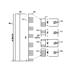
CA 02770993 2016-02-24
2
subframe for the relay nodes in an LTE-A system.
[7] Referring to FIGs. 1 and 2, reference number 343 denotes a region in
which the
control channel of a relay node is transmitted. The region 343 is a resource
informed
by higher layer signaling. The allocated resource amount, i.e. the size of
Resource
Block (12B) 401, is semi-static, and the RB used in actual transmission may
change in
every backhaul subframe.
Disclosure of Invention
Technical Problem
In the case where the control channel of the relay node is transmitted in the
allocated
control region by imitating the control channel structure of an LTE system,
the
resource amount for transmission is less than (but not equal to) the allocated
resource
and, as a consequence, a blank area, as denoted by reference number 331, in
which no
transmission occurs is distributed across the entire control channel,
resulting in waste
of resource. Although, in the case where the resource is allocated semi-
statically, the
region allocated for the relay node varies every subframe, the resource is not
easily
changed in size and is indicated fixedly, such that it is difficult to
allocate resources in
a frequency selective manner. The frequency selective resource allocation can
be
performed for the data channel for transmission to other terminals within the
cell as
well as the relay resource. In the case where the relay resource region is pre-
configured
in a large size for this, the relay must perform a plurality of blind
decodings, resulting
in an increase of relay implementation complexity. In order to perform the
frequency
selective resource allocation, the relay node must inform a large amount of
the semi-
static resource 415, resulting in increase in the number of blind decodings.
In the case
where the large amount of the semi-static resource is informed, the number of
un-
necessary blind decodings also increases especially when a small transmission
resource
is allocated, resulting in degradation of efficiency.
Solution to Problem
[91 In order that the problems of the prior art may be solved, in some
embodiments, the
present invention provides a method and apparatus for allocating control
channel resources
for a relay node within a backhaul subframe in a wireless communication system
that is
capable of dividing a resource region for the transmission of the relay node
into multiple
resource groups and allocating the resources of the same resource group to the
relay nodes
in the same transmission mode so as to reduce the number of blind decodings.
[10] Also, in some embodiments, the present invention provides a method and
apparatus
for allocating control channel resources for a relay node within a backhaul
subframe in
a wireless communication system that is capable of reducing the number of
blind
decodings at the relay node and maximizing frequency diversity gain and
frequency
selective gain between
3
resource groups.
[1 1] Also, in some embodiments, the present invention provides a
method and apparatus for
allocating control channel resources for a relay node within a backhaul
subframe in a
wireless communication system that is capable of supporting both the resource
groups in
which interleaving is performed among the control channels and the resource
groups in
which no interleaving is performed.
According to an aspect of the present invention, there is provided a method
for
configuring a control channel between a first transceiver and a second
transceiver in a
communication system, the method comprising steps of:
generating, by the first transceiver, a signaling message including
information for a
control channel, the information for the control channel comprising resource
assignment
information indicating at least one resource block and information on a
reference signal;
transmitting, by the first transceiver, the signaling message including
information for
the control channel to the second transceiver;
generating, by the first transceiver, control information and the reference
signal based
on the information for the control channel; and
transmitting, by the first transceiver, the control information and the
reference signal
generated based on the information for the control channel, to the second
transceiver.
According to another aspect of the present invention, there is provided a
method for
configuring a control channel between a first transceiver and a second
transceiver in a
communication system, the method comprising steps of:
receiving, by the second transceiver, a signaling message including
information for the
control channel generated by the first transceiver, the information for the
control channel
comprising resource assignment information indicating at least one resource
block and
information on a reference signal;
identifying, by the second transceiver, information for the control channel
based on the
signaling message; and
receiving, by the second transceiver, control information generated by the
first
transceiver based on the information for the control channel.
According to a further aspect of the present invention, there is provided an
apparatus for
configuring a control channel between a first transceiver and a second
CA 2770993 2017-10-13
,
3a
transceiver in a communication system, the apparatus for the first transceiver
comprising:
a higher layer signaling generator for generating a signaling message
including
information for a control channel, the information for the control channel
comprising
resource assignment information indicating at least one resource block and
information
on a reference signal;
a data channel generator for transmitting the signaling message including
information
for the control channel to the second transceiver;
a control channel signal generator for generating control information and the
reference
signal based on the information for the control channel; and
a control channel generator for transmitting the generated control information
to the
second transceiver.
According to a further aspect of the present invention, there is provided an
apparatus for
configuring a control channel between a first transceiver and a second
transceiver in a
communication system, the apparatus for the second transceiver comprising:
a data channel receiver receiving a signaling message including information
for the
control channel generated by the first transceiver, the information for the
control channel
comprising resource assignment information indicating at least one resource
block and
information on a reference signal;
a controller for identifying information for the control channel based on the
signaling
message; and
a control channel receiver receiving control information generated by the
first
transceiver based on the information for the control channel.
Advantageous Effects of Invention
[12] In the control channel resource allocation method and apparatus for a
relay node in a
wireless communication system, a base station allocates a large amount of
resources for
the relay control channel in the form of distinctively divided resource groups
such that it
may be possible to reduce the number of blind decodings and dynamically
allocate the
resources in every backhaul subframe. Also, the control channel resource
allocation
method and apparatus of the present invention is capable of allocating
resources for
CA 2770993 2017-10-13
,
3b
transmitting data to terminals as well as the relay control channel in a
frequency selective
manner, which may result in improvement of entire system performance.
Brief Description of Drawings
[13] The above and other objects, features and advantages of embodiments of
the present
invention will be more apparent from the following detailed description in
conjunction
with the accompanying drawings, in which:
[14] FIGs. 1 and 2 are diagrams illustrating a principle for configuring a
backhaul subframe
for the relay nodes in an LTE-A system;
[15] FIG. 3 is a diagram illustrating a structure of a subframe for use in
a Long Term
Evolution (LTE) system to which an embodiment of the present invention is
applied;
[16] FIG. 4 is a diagram illustrating an operation principle of a relay in
an LTE-A system
according to an embodiment of the present invention;
[17] FIG. 5 is a diagram illustrating a principle of allocating control
channel resources of a
relay in a wireless communication system according to a first embodiment of
the present
invention;
[18] FIG. 6 is a diagram illustrating a principle of a resource allocation
rule for the relay
control channel resource groups according to a second embodiment of the
present
invention;
[19] FIG. 7 is a flowchart illustrating a resource allocation information
transmission method
of a base station according to an embodiment of the present invention;
[20] FIG. 8 is a flowchart illustrating a resource allocation information
reception method of
a relay according to an embodiment of the present invention;
[21] FIG. 9 is a block diagram illustrating a configuration of a base
station according to an
embodiment of the present invention;
CA 2770993 2017-10-13
CA 02770993 2016-02-24
4
[22] FIG. 10 is a block diagram illustrating a configuration of a relay for
receiving the
resource allocation information according to an embodiment of the present
invention;
and
[23] FIG. 11 is a diagram illustrating a principle of allocating control
channel resource
groups to the relays according to the first embodiment of the present
invention.
Mode for the Invention
[24] Embodiments of the present invention are described in detail with
reference to the ac-
companying drawings. The same reference numbers are used throughout the
drawings
to refer to the same or like parts. Detailed description of well-known
functions and
structures incorporated herein may be omitted to avoid obscuring the subject
rnatter of
the present invention.
[25] Terms and words used in the specification and claims must be regarded
as concepts
selected as the best method of illustrating the present invention, and must be
in-
terpreted as having meanings and concepts adapted to the scope of the present
invention to understand the technology of the present invention. It should be
understood that various equivalents and modifications can be substituted.
[26] In the following, the channel and resource dedicated to a relay node
are referred to as
R-channel and R-resource.
[27] Although the following description is directed to LTE and LTE-A
systems, the
present invention can be applied to other types of wireless communication
systems in
which the base station performs scheduling.
[281 OFDM, though it is similar to the conventional Frequency Division
Multiplexing
(FDM), can obtain optimal transmission efficiency during high-speed data
transmission by maintaining orthogonality between multiple tones. In addition,
the
OFDM scheme can obtain optimal transmission efficiency during high-speed data
transmission as it has high frequency utilization efficiency and is robust
against
multipath fading.
[29] Since OFDM overlaps the frequency spectra of the subcaniers, it has
high frequency
utilization efficiency, is robust against frequency selective fading, can
reduce an Inter-
Symbol Interference (ISI) effect with the use of a guard interval, can design
simple
hardware of an equalizer, and is robust against impulse noises. Therefore, the
OFDM
scheme is used for various communication systems.
[30] ln wireless communications, high-speed, high-quality data services are
generally
h n de red by the channel environments. In wireless communications, the
channel envi-
CA 02770993 2012-02-13
WO 2011/021827 PCT/KR2010/005411
ronments suffer from frequent changes not only due to Additive White Gaussian
Noise
(AWGN) but also power variation of received signals, caused by a fading
phenomenon, shadowing, a Doppler effect brought on by movement of a terminal
and
a frequent change in a velocity of the terminal, interference by other users
or multipath
signals, etc. Therefore, in order to support high-speed, high-quality data
services in
wireless communication, there is a need to efficiently overcome the above
factors.
[31] In OFDM, modulation signals are located in the two-dimensional time-
frequency
resources. Resources on the time domain are divided into different OFDM
symbols,
and are orthogonal with each other. Resources on the frequency domain are
divided
into different tones, and are also orthogonal with each other. That is, the
OFDM
scheme defines one minimum unit resource by designating a particular OFDM
symbol
on the time domain and a particular tone on the frequency domain, and the unit
resource is called a Resource Element (RE). Since different REs are orthogonal
with
each other, signals transmitted on different REs can be received without
causing in-
terference with each other.
[32] A physical channel is a channel defined on the physical layer for
transmitting
modulation symbols obtained by modulating one or more coded bit sequences. In
an
Orthogonal Frequency Division Multiple Access (OFDMA) system, a plurality of
physical channels can be transmitted depending on the usage of the information
sequence or receiver. The transmitter and receiver negotiate the RE on which a
physical channel is transmitted, and this process is called mapping.
[33] The LTE system is a communication system which uses OFDM in the
downlink, and
Single Carrier-Frequency Division Multiple Access (SC-FDMA) in the uplink. The
LTE-A system is an advanced LTE system supporting wider bandwidth by
aggregating
two or more LTE component carriers.
[34] FIG. 3 is a diagram illustrating a structure of a subframe for use in
a Long Term
Evolution (LTE) system to which the present invention is applied.
[35] Referring to FIG. 3, resources are composed of a plurality of Resource
Blocks (RB)
in the LTE bandwidth, and an RB 109 (or 113) is defined as 12 tones in the
frequency
domain and 14 or 12 OFDM symbols in the time domain and is a basic unit of
resource
allocation. A subframe 105 is 1 ms long and consists of two consecutive
timeslots 103.
The subframe consisting of 14 OFDM symbols is referred to as a normal Cyclic
Prefix
(CP) subframe and the subframe consisting of 12 OFDM symbols is referred to as
an
extended CP subframe.
[36] The Reference Signals (RS) 119 are signals negotiated between the
mobile terminal
and the base station for the mobile terminal to estimate the channel. The RS
119 can
carry the information on the number of antenna ports, e.g., 0, 1, 2, and 3. In
the case
where the number of antenna ports is greater than 1, multiple antennas are
used.
CA 02770993 2012-02-13
WO 2011/021827 PCT/KR2010/005411
6
Although the absolute position of the RE for the RS 119 in the frequency
domain
varies depending on the cell, the interval between the RSs 119 is maintained
regularly.
That is, the RS 119 of the same antenna port maintains a distance of 6 REs,
and the
reason why the absolute position of the RS 119 varies is to avoid collision of
the RSs
of different cells.
[37] Meanwhile, the control region is located in the beginning of the
subframe. In FIG. 3,
reference number 117 denotes the control region (i.e., PDCCH). The control
region can
be configured across L OFDM symbols in the beginning of a subframe. Here, L
can
have a value of 1, 2, or 3. In the case where the amount of the control
information is
small such that one OFDM symbol is enough for transmitting the control
information,
only one OFDM symbol in the beginning of the subframe is used to transmit the
control information (L=1), and the remaining 13 OFDM symbols are used to
transmit
data. The value L is used as the basic information for demapping at the
receiver and
thus, if it is not received, the receiver cannot recover the control channel.
In
Multimedia Broadcast over a Single Frequency Network (MBSFN), the value of L
is 2.
Here, the MBSFN is a channel for transmitting broadcast information. If the
subframe
indicates the broadcast information, the LTE terminal receives in the control
region but
not in the data region of the subframe.
[38] The reason why the control signaling is transmitted in the beginning
of the subframe
is for the terminal to determine whether the subframe is intended for itself
and, as a
consequence, to determine whether to receive the data channel (i.e., the
Physical
Downlink Shared CHannel (PDSCH)). If it is determined that there is no data
channel
destined to the terminal, the terminal can enter an idle mode and save power.
[39] The LTE standard specifies three downlink control channels: Physical
Control
Format Indicator CHannel (PCFICH), Physical Hybrid ARQ Indicator CHannel
(PHICH), and Packet Data Control CHannel (PDCCH); and these control channels
are
transmitted in units of Resource Element Group (REG) 111 within the control
region
117.
[40] The PCFICH is the physical channel for transmitting the Control
Channel Format
Indicator (CCFI) to the terminal. CCFI is 2-bits long and indicates the number
of
symbols occupying the control region in a subframe "L". Since a terminal can
recognize the number of symbols of the control region based on the CCFI, the
PCFICH
must be the first channel to be received in a subframe except when the
downlink
resource is allocated persistently. Since it is impossible to know the value
of L before
receiving the PCFICH, the PCFICH is always mapped to the first OFDM symbol of
each subframe. The PCFICH is in 4 resource groups formed by equally separating
16
subcarriers in frequency.
[41] The PHICH is the physical channel for transmitting downlink ACK/NACKs.
PHICH
CA 02770993 2012-02-13
WO 2011/021827 PCT/KR2010/005411
7
is received by the terminal which is transmitting data in the uplink.
Accordingly, the
number of PHICHs is in proportion to the number of terminals that are
transmitting in
the uplink. PHICH is transmitted in the first OFDM symbol (LPHICH=1) or three
OFDM symbols (LPH1CH=3) of the control region. The PHICH configuration in-
formation (number of channel, LPHICH) is broadcast through the Primary
Broadcast
Channel (PBCH) such that all of the terminals acquire the information at their
initial
connection to the cell. Also, PHICH is transmitted at a predetermined position
per cell
like the PCFICH such that the terminals can acquire the PHICH configuration in-
formation by receiving the PBCH when the terminal connects to the cell
regardless of
other control channel information.
[42] The PDCCH 117 is the physical channel for transmitting data channel
allocation in-
formation or power control information. The PDCCH can be transmitted with
different
channel coding rates according to the channel condition of the target
terminal. Since
Quadrature Phase Shift Keying (QPSK) is always used for PDCCH transmissions,
changing the channel coding rate requires change of the resource amount for a
PDCCH. When the channel condition of the terminal is good, a high channel
coding
rate is used to save the resource. In contrast, when the channel condition of
the
terminal is bad, a low channel coding rate is used to increase reception
probability at
the terminal even at the cost of large amounts of resources. The resource
amount for
each PDCCH is determined in unit of Control Channel Element (CCE). Each CCE is
composed of 5 Resource Element Groups (REG) 111. In order to secure diversity,
the
REGs of the PDCCH are arranged in the control region after interleaving has
been
performed.
[43] In order to multiplex several ACK/NACK signals, a Code Division
Multiplexing
(CDM) technique is applied for the PHICH. In a single REG 111, 8 PHICH signals
are
multiplexed into 4 real number parts and 4 imaginary number parts by means of
the
CDM technique and repeated as many as NPHICH so as to be distributed in the
frequency domain to obtain frequency diversity gain. By using NPHICH REG 111,
it
is possible to form the 8 or less PHICH signals. In order to form more than 8
PHICH, it
is necessary to use other NPHICH REG 111.
[44] After assigning resources for the PCFICH and PHICH, a scheduler
determines the
value of L, maps the physical channels to the REG 111 of the assigned control
region
117 based on the value of L, and performs interleaving to obtain frequency
diversity
gain. The interleaving is performed on the total REG 111 of the subframe 105
de-
termined by the value of L in units of REG in the control region 117. The
output of the
interleaver in the control region 117 is capable of preventing Inter-Cell
Interference
(ICI) caused by using the same interleaver for the cells and obtaining the
diversity gain
by distributing the REGs 111 of the control region 117 across one or more
symbols.
CA 02770993 2012-02-13
WO 2011/021827 PCT/KR2010/005411
8
Also, it is guaranteed that the REGs 111 forming the same control channel are
dis-
tributed uniformly across the symbols per control channel.
[45] Recently, research has been conducted on the LTE-A system as an
advanced LTE
system. Particularly, the research has been focused on the extension of the
coverage
with relays which remove shadow areas in the cell and wireless backhaul for
connecting the base stations with the relay which operates in the same manner
as the
base station.
[46] FIG. 4 is a diagram illustrating an operation principle of a relay in
an LTE-A system
according to an embodiment of the present invention.
[47] Referring to FIG. 4, the relay 203 receives data transmitted from the
base station 201
and forwards the data to the terminal 205. There can be multiple communication
links
in the cell having a relay node.
[48] The base station 201 and the terminal 207 are connected through a link
A 209, and
the relay node 203 and the terminal 205 are connected through a link C 213.
Since the
relay node 203 is regarded as a base station in view of the terminal 205, the
link A 209
and link C 213 can be considered as in the same transmission region as denoted
by
reference number 219.
[49] The base station 201 and the relay 203 are connected through a link B
211, and the
link B 211 is used to transmit the data destined to the terminal 205 connected
to the
relay 203 or exchange higher layer signaling between the base station 201 and
the relay
203.
[50] Reference numbers 215 and 217 denote the subft-ames canying the data
transmitted
from the base station 201 to the terminal 205 via relay 203. The subframes
denoted by
reference number 215 show the region in which the base station 201 transmits
data to
the relay 203 and the terminal 207, and the frames denoted by reference number
217
show the region in which the relay node 203 transmits data to the terminal 205
or
receives data from the base station 201. The subframes denoted by reference
number
219 show the region in which the terminal 207 connected to the base station
201, or the
terminal 205 connected to the relay 203, receives data from the base station
201 or the
relay 203, respectively.
[51] Reference number 221 denotes a backhaul subframe transmitted on the
backhaul
link. The backhaul subframe can be used to carry data transmitted to the relay
node
203 and the terminal 207 connected to the base station 201 or dedicated to
backhaul
data transmission.
[52] Reference number 235 denotes a resource region allocated for the
backhaul
transmission. The base station 201 transmits the control channel 225 in every
subframe, and the relay 203 also transmits the control channel in the same
manner. The
relay 203 cannot transmit and receive data simultaneously. Accordingly, when
the
CA 02770993 2012-02-13
WO 2011/021827 PCT/KR2010/005411
9
relay 203 transmits the control channel, it cannot receive the control channel
in-
formation transmit by the base station 201. The base station 201 transmits the
data to
the relay 203 in the region 235 of the backhaul subframe after the
transmission of the
control channel such that the relay 203 receives the information of the
corresponding
region. After the transmission in the data channel region 235, it is necessary
to switch
from transmission to reception. Accordingly, a blank region 229 is required.
[53] A description is now made of the method for a base station to allocate
resources to a
relay in a broadband wireless communication system.
[54] First Embodiment
[55] FIG. 5 is a diagram illustrating a principle of allocating control
channel resources of
a relay in a wireless communication system according to a first embodiment of
the
present invention.
[56] In this embodiment, when allocating the backhaul subframe control
channel
resources of the relay, the base station divides the resource region for the
relay into a
plurality of resource groups and allocates the same resource group to relays
operating
in the same transmission mode so as to reduce the number of blind decoding
attempts.
At this time, the base station allocates resources to the relay in advance and
informs the
relay of the currently used resource group and transmission mode so as to
reduce the
number of blind decoding attempts and maximize the frequency diversity gain
and
frequency selective gain among the groups. Also, the base station supports the
group in
which interleaving is performed and the group in which no interleaving is
performed.
[57] Referring to FIG. 5, the resource allocation method according to the
first em-
bodiment of the present invention informs the relay of the resources allocated
for the
relay in the cell in the form of a plurality of resource groups rather that a
single
resource group.
[58] In the conventional resource allocation method for the relay control
channel
transmission as depicted in FIG. 2, the entire resource region is informed. In
order to
allocate the resources in a frequency selective manner in the conventional
method, the
base station must allocate large amounts of resources across the entire
bandwidth 401
in advance. Accordingly, it is difficult to perform the frequency selective
resource al-
location and the frequency diversity resource allocation.
[59] In the resource allocation method according to the present invention,
the base station
segments the entire resource region into a plurality of resource groups and
informs the
relay of the currently used resource group as shown in FIG. 5, unlike the
conventional
resource allocation method in which the entire resource region is dealt with
as a single
resource, as shown in FIG. 2.
[60] In FIG. 5, reference numbers 519, 521, 523, and 525 denote the semi-
static resource
groups that are obtained by dividing the single resource. The resource groups
are
CA 02770993 2012-02-13
WO 2011/021827 PCT/KR2010/005411
regions in which the Relay-PDCCH (R-PDCCH) is transmitted, and the relay
attempts
blind decodings to the R-PDCCH in the resource group assigned for itself,
resulting in
a reduction of the number of blind decodings. That is, the relay performs the
blind
decoding in such a manner that the relay is assigned a resource group (one of
the
resource groups 519, 521, 523, and 525) in advance in which its own relay
control
channel exists and searches for its relay control channel in the selected
resource group
region so as to reduce the number of blind decoding attempts. The relay can be
allocated one or more resource groups.
[61] For example, assuming that a total of 32 Physical Resource Blocks
(PRBs) are
indicated, if the resource is used as a single group as shown in FIG. 2, the
number of
blind decoding attempts is 32+16+8+4=60. In contrast, if the resource is
divided into 4
groups as shown in FIG. 5 according to an embodiment of the present invention,
the
number of blind decoding attempts is 8+4+2+1=15. This is because the resource
al-
location method of the present invention allocates one small resource group
per relay
such that the relay searches only the allocated resource group for its control
channel
with blind decodings.
[62] In order to perform blind decoding in this manner, the relay has to
know the total
number of resource groups and the index and size of each resource group. Ac-
cordingly, the base station informs the relay of the resource group
information, i.e. the
number of resource groups and index and size of each resource group by higher
layer
signaling. The resource group information can be transmitted in the form of
the in-
formation about all of the resource groups by means of the system information
or in
the form of the information about the resource group allocated to each relay
by means
of Radio Resource Control (RRC) signaling.
[63] Tables 1 and 2 show configurations of resource group information
informed to the
relay according to an embodiment of the present invention. Table 1 is a
message
format of system information carrying the resource information, and Table 2
shows a
message format of RRC signaling carrying the resource information.
[64] Table 1
CA 02770993 2012-02-13
WO 2011/021827
PCT/KR2010/005411
11
[Table 1]
R-PDCCH configurationi
Semi-static resource group{
Number0fResoirceGroup
Resoui-ceAllocation 1,
ResourceAllocation 2,
ResourceAllocation N,
1L651 Table 1
shows the case where the resource is divided into N resource groups. The
resource group information is transmitted to the relay by higher layer
signaling such
that the relay is notified of the number of resource groups and sizes of
individual
resource groups. The higher layer signaling can be done with System
Information
Block 2 (SIB2). In the case of using system information, the base station is
needed to
inform the relay of only the resource group index for the relay to use to
acquire the
resource configuration information in the RRC signaling. In the case where the
resource group information is not transmitted in the system information, the
base
station has to send the information about the resource to be used by the relay
in RRC
signaling along with the configuration information. Table 2 shows the
information per
resource group when the resource group information is transmitted in RRC
signaling.
[66] Table 2
[Table 2]
Semi-static resource group configurationi
Semi-static resource groupi
ResourceAllocation information,
Interleaver on/off
CRS or DRS
DM RS port index(if DRS is used)
}
[67] As shown in Table 2, the resource group information includes the
resource allocation
information, the information on the control channels multiplexed in the
allocated
resource, and the information related to the reference signal such as the type
of
reference signal. This is because the relays operating in the same
transmission mode
CA 02770993 2012-02-13
WO 2011/021827 PCT/KR2010/005411
12
are allocated the same resource group and the control channels can be
interleaved. The
resource allocation information informs the relay of the resource region in
which the
relay received the information attempts control channel demodulation among the
resources carrying the entire control channels. This region can be informed by
a PRB
index or a set of PRB. This will be further described with reference to the
resource al-
location method in a second embodiment as shown in FIG. 6. The relay also can
check
whether its control channel is multiplexed with the control channels of other
relays by
referencing the interleaver on/off information. If the interleaver is on, the
relay starts
receiving the information with the recognition that its control channel is
interleaved
with the control channels of other relays. Also, the relay receives the
information about
the type of the reference signal used for demodulating the control channel
intended for
itself. It is noted that all of the relays that received the same group
resource in-
formation receive the control channel using the same reference signal (RS).
That is, if a
specific resource group is allocated to a relay, this means that the relays
allocated the
same resources use the same interleaving scheme and reference signal. In other
words,
the relays operating in the same transmission mode (whether to use
interleaving and
type of reference signal) are allocated the same resource group.
[68] FIG. 11 is a diagram illustrating a principle of allocating control
channel resource
groups to the relays according to the first embodiment of the present
invention.
[69] Referring to FIG. 11, if there is the entirely pre-configured resource
as denoted by
reference number 1101, the resource is divided into a plurality of resource
groups as
denoted by reference number 1102. At this time, the resource is divided
depending on
the transmission mode appropriated for individual groups determined by the
base
station. The relays 1103 are grouped into relay groups 1104, 1105, and 1106 in
as-
sociation with the resource group. At this time, a group can be composed of
one or
more relays, and a relay can be included in multiple groups. A relay group is
formed
with the relays operating in the same transmission mode.
[70] Once the relay groups are formed, each relay group is allocated a
resource group.
Each relay group is allocated a search space for blind decoding in the
allocated
resource group. Individual search spaces are mapped to corresponding resource
groups
as denoted by reference numbers 1108, 1111, and 1114. At this time, the relays
belonging to the same group have the same search space or respective search
spaces.
[71] Each resource group is allocated according to the transmission mode of
the relay
control channel. The relay allocated the resource group denoted by reference
number
1105 can be configured with a Dedicated RS (DRS) as denoted by reference
number
1110 without interleaving as denoted by reference number 1109. The relay
allocated
the resource group denoted by reference number 1106 can be configured with a
Common RS (CRS) as denoted by reference number 1113 without interleaving as
CA 02770993 2012-02-13
WO 2011/021827 PCT/KR2010/005411
13
denoted by reference number 1112. The relay allocated the resource group
denoted by
reference number 1104 can be configured with CRS as denoted by reference
number
1116 and with interleaving as denoted by reference number 1115. Here, the in-
terleaving includes REG level interleaving, CCE level interleaving, and PRB
level in-
terleaving.
[72] Second Embodiment
[73] As described above, in the case where the resource is divided into a
plurality of
resource groups to be allocated for control channels of relays, the physical
resources
mapped to the virtual resources of groups 511, 513, 515, and 517 of FIG. 5 can
be
arranged across consecutive Physical Resource Blocks (PRBs) or distributed
PRBs in
the system bandwidth. A description is now made of the resource allocation
rule for
mapping virtual resources to the physical resources.
[74] FIG. 6 is a diagram illustrating a principle of a resource allocation
rule for the relay
control channel resource groups according to a second embodiment of the
present
invention.
[75] Reference numbers 601, 603, 605, and 607 denote resource groups for
transmitting
the relay control channels. Here, each resource group can be an RB or an RBG.
[76] As aforementioned, the base station transmits the resource group
information by
higher layer signaling. The base station also transmits the resource
allocation rule by
higher layer signaling. The resource allocation rule is the rule for mapping
virtual
resources to physical resources.
[77] The relay processes the signal of its relay control channel based on
the resource
group information received in advance. In this embodiment, when the relay
performs
blind decoding on the signal of the control channels, the number of blind
decoding
attempts is reduced significantly.
[78] The received relay control channel includes the information on the
virtual resource
(one of 609, 613, and 617). This information can be the index of the virtual
resource
allocated to the relay. If the index of the virtual resource is acquired, the
relay can
recognize the actual transmission resources (611, 615, and 619) allocated to
itself
according to the resource allocation rule received in advance by higher layer
signaling.
The resource allocation rule includes individual resource allocation sub-rules
as
denoted by reference numbers 609 and 611, 613 and 615, and 617 and 619; these
sub-
rules are referred to as first, second, and third rules for simplifying the
explanation.
[79] The first rule is described with reference to the part denoted by
reference numbers
609 and 611. The first rule is designed in consideration of the terminal
multiplexing in
the cell and resource allocation in units of RB Groups (RBGs). According to
the first
rule, the actual resources allocated to the virtual resources are mapped on
contiguous
frequencies. This mapping scheme is efficient in the case where frequency
selectivity
CA 02770993 2012-02-13
WO 2011/021827 PCT/KR2010/005411
14
of the relay control channels or the terminal channels is very high.
[80] The second rule is described with reference to the part denoted by
reference numbers
613 and 615. The second rule is designed in consideration of the frequency
diversity
and resource allocation in units of RBGs. In the case where the frequency
selectivity is
not high, it is advantageous to distribute the allocated resources across the
entire
bandwidth in view of diversity gain and inter-cell interference uniformity. In
the
second rule, the resources allocated in a resource group are distributed far
enough in
the frequency domain.
[81] The third rule is described with reference to the part denoted by
reference numbers
617 and 619. The third rule is designed in consideration of the frequency
diversity,
virtual resource allocation in units of RBGs, and mapping of the virtual
resources to
the physical resources in units of RBs. Although the virtual resources are
allocated in
units of RBGs as denoted by reference number 617, the virtual resources are
mapped
to the physical resources in the RBG in units of RBs. The third rule is robust
to in-
terference and advantageous for multiplexing scheduled data of the terminals
since it
can obtain higher frequency diversity gain as compared to the second rule.
[82] The consecutive resources can be allocated to the relays that use
spatial multiplexing
and/or beamforming techniques in order to exploit the frequency selective
charac-
teristic. The distributed resources can be used for diversity transmission
using the
normal reference signal. In this manner, the system can allocate the resources
in con-
sideration of the frequency characteristic of the relay channel and reference
signal or
the transmission mode. By performing multiplexing (interleaving) on the
control
channels allocated resources in the same resource group, it is possible to
guarantee the
diversity of the control channels. The control channel interleaving can be
performed by
using a REG level interleaver as explained in the first embodiment.
[83] The method for configuring a plurality of resource groups for resource
allocation to
relay nodes and signaling the resource allocation rule for mapping the
resources in the
individual resource group, the control channel, and the transmission mode for
transmitting/receiving the resource group information has been described
hereinabove.
A method for reducing the number of blind decoding attempts in order to reduce
the
data overhead of the resource group information is described hereinafter. The
resource
group indicator includes the indices of the resource groups allocated to
individual
relays, and each relay can reduce the number of blind decoding attempts to
search for
its group indicator using the resource group indicator.
[84] Third Embodiment
1851 In a third embodiment of the present invention, a Relay Physical
Control Format
Indicator CHannel (R-PCFICH) is used for transmitting the resource group
indicator.
The R-PCFICH is transmitted in a fixed position and, if the semi-static
resource group
CA 02770993 2012-02-13
WO 2011/021827 PCT/KR2010/005411
is divided as described in the first embodiment, the R-PCFICH can be
transmitted at
predetermined positions according to the number of the semi-static resource
groups.
That is, when the R-PDCCH is received in the initial connection process, there
are
positions to transmit the R-PCF1CH in individual resource groups, and the
relay
performs blind decodings on the regions carrying the R-PCFICH rather than the
relay
control channel regions of the entire resource groups. In this manner, the
relay
performs demodulation on the number of resource groups that receive the R-
PCFICH
value. The R-PCFICH carries the index indicating the resource group including
the
control channel of the relay. In this manner, the relay can reduce the number
of blind
decoding attempts to find the resource group allocated for its relay control
channel.
[86] Fourth Embodiment
[871 In a fourth embodiment, a common relay control channel, i.e. common R-
PDCCH, is
used to implement a method for indicating a dynamic resource group. In this
case, the
relay must receive the common R-PDCCH transmitted by the base station in
addition
to the relay-specific control channel. In this common control channel, the
index of the
resource group used in the next backhaul subframe of the corresponding relay
is
transmitted. Since the resource group to be used in the next backhaul subframe
is
recognized with receipt of the common R-PDCCH, the relay can reduce the number
of
blind decoding attempts.
[88] A description is now made of a method for a base station to transmit
the resource al-
location information. FIG. 7 is a flowchart illustrating a resource allocation
in-
formation transmission method of a base station according to an embodiment of
the
present invention.
[89] Referring to FIG. 7, the base station configures the information on
the resource
groups in consideration of a number of relays in the cell and the channel
conditions
between the base station and the relays in step 703. Next, the base station
selects RBs
or RBGs to be allocated in the individual semi-static resource groups in step
705. Such
a selection process is performed with one of the three resource allocation
rules
described with reference to FIG. 6. Next, the base station transmits the
resource group
information, per-group resource allocation information, and control channel
transmission mode information to the relays by means of higher layer signaling
in step
707.
[90] In the case of using the resource group indicator indicating the semi-
static resource
allocation group mapped to the resource allocated to the corresponding relay,
the base
station transmits the resource group indicator indicating the resource group
using the
current backhaul subframe in the R-PCF1CH or R-PDCCH in step 709. In the case
where the resource group indicator is not used, step 709 is skipped.
[91] Here, the resource groups are updated over a long interval, and the
resource group
CA 02770993 2012-02-13
WO 2011/021827 PCT/KR2010/005411
16
indicator is updated in every backhaul subframe.
[92] A description is now made of a method for a relay to receive the
resource allocation
information. FIG. 8 is a flowchart illustrating a resource allocation
information
reception method of a relay according to an embodiment of the present
invention.
[93] Referring to FIG. 8, the relay receives the resource group information
for
transmitting the relay control channel, the resource allocation rule
indicating how to
map the virtual resources of the relay control channel to the physical
resources, and the
transmission mode of the control channel in advance by means of higher layer
signaling in step 803. In step 807 the relay receives the control channel
based on the
resource group information and control channel transmission mode information
acquired at step 803.
[94] In the case of using the resource group indicator, the relay checks
whether the current
subframe is a backhaul subframe and, if so, checks the resource group
indicator and
selects the resource group to attempt receiving its control channel in the
current
subframe using the resource group indicator in step 805. The resource group
indicator
can be received in the R-PCFICH or common R-PDCCH.
[95] Next, the relay performs blind decoding on the relay control channels
using the
resource group information or the resource group indicator in step 807. In the
case of
using the resource group indicator, the relay searches for the resource group
indicated
by the resource group indicator and finds its relay control channel by perform
blind
decoding in the found resource group.
[96] Next, the relay checks whether the R-PDCCH is successfully received
and, if so,
acquires the scheduling information from the R-PDCCH to receive data in step
809.
That is, the relay checks the virtual resource allocated to itself from its
relay control
channel and recognizes the physical channel actually allocated to itself
according to the
resource allocation rule received in advance through the virtual resource.
[97] A description is now made of the configuration of a base station for
transmitting the
resource allocation information with reference to FIG. 9. FIG. 9 is a block
diagram il-
lustrating a configuration of a base station according to an embodiment of the
present
invention.
[98] As shown in FIG. 9, the base station includes a controller 901, a
resource allocator
903, a higher layer signaling generator 905, a data channel generator 907, a
resource
indicator generator 909, a control channel signal generator 911, and a control
channel
generator 913.
[99] The controller 901 performs scheduling and allocates resources to
individual relays.
The controller 901 also generates the resource groups to be indicated to the
individual
relays by grouping the relay backhaul control channels by means of the
resource
allocator 903. Here, the size of a resource group and the number of resource
groups
CA 02770993 2012-02-13
WO 2011/021827 PCT/KR2010/005411
17
can vary depending on the channel conditions.
[100] The higher layer signaling generator 905 generates information on the
resource group
information and control channel transmission mode in the format as described
with
reference to Tables 1 and 2. The higher layer signaling generator 905 also
generates
the information on the resource allocation rule with which the resource is
allocated,
whether an interleaver is used or not, and the type of reference signal used
for control
channel decoding.
[101] The group resource information and transmission mode information can
be
transmitted through a data channel. Accordingly, the data channel generator
907
transmits the resource group information and the resource allocation rule
mapped to
the data channel.
[102] When using the resource group indicator as described in the third and
fourth em-
bodiments, the controller 901 controls the resource indicator generator 909 to
generate
the resource group indicator using the resource group information of a
specific relay as
a result of scheduling in addition to the aforementioned steps.
[103] The resource indicator generator 909 generates the resource indicator
which is
transmitted in one of the R-PCFICH and common R-PDCCH as described above. The
control channel signal generator 911 generates the control channel signal
including the
resource indicator, and the control channel generator 913 maps the control
channel in-
formation including the resource indicator to the control channel to be
transmitted.
[104] FIG. 10 is a block diagram illustrating a configuration of a relay
for receiving the
resource allocation information according to an embodiment of the present
invention.
[105] As shown in FIG. 10, the relay includes a control channel receiver
1001, a control
channel blind decoder 1005, a data channel decoder 1007, a data channel
receiver
1009, and a controller 1013.
[106] The data channel receiver 1009 receives a data channel and extracts
higher layer
signaling 1011 from the data channel. The higher layer signaling 1011 includes
allocated resource group information, resource allocation rule with which the
virtual
resources are mapped to the physical resources, and control channel
transmission mode
information. The data channel receiver 1009 also transfers the extracted
resource group
information and the resource allocation rule to the controller 1013.
[107] The control channel receiver 1001 receives a channel such as the R-
PCFICH and
common R-PDCCH and extracts the resource group indicator 1003 from the control
channel.
[108] The resource group indicator 1003 can be selectively included. In the
case where the
resource group indicator is not used, the control channel blind decoder 1005
checks the
resource group information provided by the controller 1013, searches for its
resource
group by performing blind decoding, and finds its R-PDCCH by performing blind
CA 02770993 2016-02-24
18
decoding on the found resource group.
[109] In the case where the resource group indicator is used, the control
channel blind
decoder 1005 checks the number of resource groups and sizes of individual
resource
groups using the resource group information output by the controller 1013 and
finds its
resource group indicated by the resource group indicator 1003. Next, the
control
channel blind decoder 1005 finds its relay control channel by performing blind
decoding on the found resource group.
[1101 After finding its own relay control channel, the control channel
blind decoder 1005
checks the position of the virtual resource allocated to relay from the found
relay
control channel. Next, the control channel blind decoder 1005 receives the
resource al-
location rule provided by the controller 1013 and checks the position of the
physical
resource allocated to the relay according to the resource allocation rule.
[111] The data channel decoder 1007 checks the position of the physical
resource allocated
to the relay by means of the control channel blind decoder 1005 and receives
the data
in the corresponding position of the data channel.
[112] The configurations of the base station and relay according to
embodiments of the
present invention have been described hereinabove.
[113] As described above, in the control channel resource allocation method
and apparatus
for a relay node in a wireless communication system, a base station allocates
a large
amount of resources for the relay control channel in the form of distinctively
divided
resource groups such that it is possible to reduce the number of blind
decodings and
dynamically allocate the resources in every backhaul subframe. Also, the
control
channel resource allocation method and apparatus of the present invention is
capable of
allocating resources for transmitting data to terminals as well as the relay
control
channel in a frequency selective manner, resulting in improvement of entire
system
performance.
[114] Although embodiments of the present invention have been described in
detail
hereinabove, it should be clearly understood that many variations and/or
modifications
of the basic inventive concepts herein taught which may appear to those
skilled in the
present art will still fall within the scope of the present invention. as
defined in the
appended claims.