Note: Descriptions are shown in the official language in which they were submitted.
CA 02771001 2012-03-08
1
Threaded sleeves
The invention relates to a threaded sleeve made of metal for screwing into a
receiving opening of a work piece.
Such threaded sleeves are also called bushings or threaded bushes. They
comprise a core and a thread provided on the outer surface of the core. The
receiving opening of the work piece into which the threaded sleeve is to be
screwed can, for instance, be a boring. The receiving opening does normally
not
have an own thread.
Threaded sleeves normally have a hollow space within which an internal thread
for receiving a complementary connecting element, for instance a screw, is
provided. Thus, the threaded sleeve itself is no screw. The hollow space can
extend along the entire length of the threaded sleeve or only project into the
same from the front side end of the threaded sleeve. An internal thread can be
formed in the inner wall of the threaded sleeve which can extend along the
entire hollow space or only along a part of the same.
With the threaded sleeves which are known from the state of the art problems
arise when the same are screwed into receiving openings of work pieces, in
particular when the work pieces are made of wood. Cracks may occur within the
material of the work piece. In most cases the reason for this is that, due to
the
configuration of the thread of the threaded sleeve, the work piece material is
deformed. This deformation creates tensions which are so strong that the work
piece material ruptures or exits from the receiving opening, thus preventing a
flush assembly. Moreover, the material may heat up during the screw-in process
and break off when the stress gets too high.
It is the object of the present invention to provide a threaded sleeve where,
after the screwing-in, a sufficient tensile strength of the connection between
the threaded sleeve and the material is ensured but where, during the screwing-
in, no damage is caused at the work piece and/or the same is reduced. The
CA 02771001 2012-03-08
2
above-mentioned object is accomplished by means of a threaded sleeve with
the features set out in claim 1.
The threaded sleeve is normally integrally made of metal. By means of the
screwing-in, i.e. by a rotation around the longitudinal axis of the threaded
sleeve, the threaded sleeve is inserted into the receiving opening of a work
piece. When screwed into a receiving opening, the thread of the threaded
sleeve creates a thread and/or a counter-thread in the (smooth-walled) surface
of the receiving opening. As a general rule and depending upon the thread
profile of the threaded sleeve, the thread and/or the counter-thread is
created
in the wall of the receiving opening by the displacement or cutting of the
work
piece material.
In the present invention, the creation of the thread in the smooth-walled
surface of the receiving opening is accomplished by a particularly efficient
cutting. The thread profile of the threaded sleeve has a very small flank
angle
within the range from 25 to 35 . The thread profile is the cross-sectional
outline of the thread and/or of the thread turn. The flank angle is the angle
included by the sides which form the thread profile. By choosing a smaller
flank
angle, a better cutting effect for cutting into the wall of a receiving
opening is
achieved resulting in a lower torque which is required when the threaded
sleeve
is screwed in. The thread of the threaded sleeve does not displace, compress
or
compact the material of the work piece but cuts it, wherein an adequate
stability of the flank angle must be ensured so that the required tensile
strength
is maintained. Consequently, a breaking of the work piece occurs less often,
and
the thermal heating-up of the material, as happens in particular in wood, is
substantially reduced. In addition, owing to the better cutting process, the
material of the work piece into which the threaded sleeve is screwed is
damaged less, as is for instance the case with the formation of small cracks
which later on result in a bad connection between the threaded sleeve and the
material. Thus, all in all, a substantially increased tensile strength of the
connection is brought about.
CA 02771001 2012-03-08
3
Furthermore, the inventive threaded sleeve has a comparatively great pitch of
thread. Pitch of thread means the distance in parallel with the longitudinal
axis
between the centres of two adjacent thread turn sections. In single threads,
the
pitch of thread corresponds to the lead of the thread which is the distance by
which a threaded sleeve is screwed into a material during one turn of 360 .
A great pitch of thread is advantageous in particular for screwing into wood
since less wood fibres are damaged and a stronger connection is achieved.
Nevertheless, the pitch of thread must not be too great since otherwise the
tensile strength decreases again. The inventive threaded sleeve overcomes this
contradiction by means of a pitch of thread with the 0.1-fold to 0.4-fold of
the
outer diameter of the threaded sleeve.
Also in respect of the thread depth, the threaded sleeve according to the
invention finds a compromise between an increase in the tensile strength of
the
connection between the threaded sleeve and the work piece by means of a
particularly great thread depth and the damage which is simultaneously caused
to the material. Here, the thread depth is the difference between the outer
diameter of the threaded sleeve which includes the thread and the outer
diameter of the core (without the external thread). In other words, the thread
depth is the height of the thread profile. According to the present invention,
the
thread depth is the 0.02-fold to 0.2-fold of the outer diameter of the
threaded
sleeve.
In a preferred embodiment of the inventive threaded sleeve, the thread profile
of the threaded sleeve has no curvature, in particular within the area of the
thread profile that is spaced most from the core. Consequently, the profile of
the thread is no round thread and does not have, in general, a radius of
curvature in any region. Thereby, a particularly good cutting effect of the
threaded sleeve is achieved.
Furthermore, the thread profile in a preferred embodiment has a substantially
pointed configuration. This means that the sides of the thread substantially
CA 02771001 2012-03-08
4
form a tip in the point of the thread profile that is spaced most from the
core.
During the manufacturing process, a thread profile with a perfect tip cannot
always be ensured. Between the ends of the sides of the thread which face
away from the core of the threaded sleeve, an elevated plane can be created
which runs substantially in parallel to the core of the threaded sleeve. This
elevated plane should, however, maximally have only 10 %, preferably
maximally 5 %, of the distance which the sides include between their ends
facing towards the core in order to provide for a substantially pointed
profile.
Moreover, it is preferred that the flank angle is constant along the entire
thread
depth. This is the case when the sides of the thread have neither kinks nor
curves in the thread profile but can be described by a straight line each with
a
constant slope.
As a general rule, the threaded sleeve can be used for screwing into the
receiving opening of a work piece of any kind. In a preferred embodiment the
inventive threaded sleeve is, however, designed for screwing into a work piece
made of wood so that the threaded sleeve and the wooden work piece
constitute a joint system. It is particularly advantageous that the inventive
threaded sleeve does not compact or compress the wood and/or the cell
structure of the wood but only cuts the wood instead. This results in a
considerably increased tensile strength between the threaded sleeve and the
wooden work piece. This effect is further enhanced by the structure of the
wood. As a general rule, wood has a tensile strength that is greater in the
longitudinal direction of the annual rings than in the transverse direction
because the different annual rings have different properties of the material
and
since often connections with a lower degree of stressability exist between
individual annual rings. If the wood and/or its cell structure is compressed
and
thus destroyed due to the insertion of a threaded sleeve, the cohesion between
the individual annual rings is further reduced and the tensile strength
between
the threaded sleeve and the work piece of wood decreases.
CA 02771001 2012-03-08
Preferably, the flank angle is 28 to 32 , particularly preferred 29 to 31 ,
and
still more preferred exactly 30 .
Preferably, the pitch of thread is the 0.15-fold to 0.35-fold and particularly
preferred the 0.16-fold to 0.33-fold of the outer diameter of the threaded
sleeve.
Moreover, the preferred thread depth of the thread is the 0.04-fold to 0.18-
fold
and particularly preferred the 0.06-fold to 0.16-fold of the outer diameter of
the
threaded sleeve.
It has become evident that, above all with the above-mentioned particularly
preferred ranges, an extremely good tensile strength of the connection
between the threaded sleeve and the work piece can be attained.
In another preferred embodiment the core of the threaded sleeve substantially
has a constant diameter throughout. Here, both the outer diameter and the
inner diameter of the core, which is at the same time the diameter of the
hollow space of the core (screw receiving opening), can be constant
throughout.
A particularly preferred configuration is the inventive threaded sleeve made
of
steel, brass or die-cast zinc.
A preferred embodiment of the invention is shown in the figures which
schematically show:
Fig. 1: a side view and a longitudinal section of an inventive threaded
sleeve, and
Fig. 2: a top view of a threaded sleeve of Fig. 1.
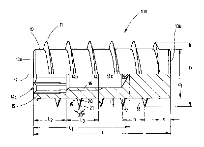
Fig. 1 shows an inventive threaded sleeve 100 of a length L which comprises a
cylindrical core 10 and a single-thread thread 11 provided outside on the core
CA 02771001 2012-03-08
6
10. The lower half of Fig. 1 shows a length along the longitudinal axis 12 of
the
threaded sleeve 100 while a side view of the threaded sleeve 100 is shown in
the upper half.
In the upper half of the figure it can be seen how the thread turn of the
single-
thread thread 11 helically winds around the core 10 from the one end 13a to
the other end 13b of the threaded sleeve 100 with the area along length a at
the end 13b of the threaded sleeve 100 being left out. This thread-free area
along length a is used for the insertion of the threaded sleeve 100 into a
receiving opening (not shown here) into which the threaded sleeve 100 is
screwed. Furthermore, it can be seen that the threaded sleeve 100 conically
tapers at its two ends 13a, 13b.
The lower half of the figure shows that the illustrated threaded sleeve 100
has a
cylindrical hollow space 14 which projects from end 13a of threaded sleeve 100
by length Li into the threaded sleeve 100. The hollow space 14 has four sub-
areas 14a, 14b, 14c, 14d which directly follow each other in the longitudinal
direction of threaded sleeve 100. In this embodiment, length L1 covers at
least
half of the length L of the threaded sleeve 100. Along length L2 the hollow
space
14 is designed as a receiving area 14a for a tool for the screwing-in of the
threaded sleeve 100. In the receiving area 14a notches 15 in parallel to the
longitudinal axis are worked into the inner wall of core 10 into which the
tool
can grip. In this embodiment, the receiving area 14a serves for holding a
special
hexagon socket screw key (not shown here).
Along the lengths L2 and L3 the threaded sleeve 100 from Fig. 1 is provided
with
an internal thread 16 for the screwing-in of another connecting element (not
shown here), for instance of a screw. Through the provision of the receiving
area 14a with the notches 15, the internal thread 16 was in part reduced
within
the area L2. Within the area 14b along length L3 the internal thread 16 is
unreduced. In Fig. 1, the unreduced internal thread 16 is not illustrated by a
profile like the externally provided thread 11 but by the boundary of a
parallelogram with L3 as the long side and the thread depth of the internal
CA 02771001 2012-03-08
7
thread 16 as the short side. In the area 14c of the hollow space 14 of
threaded
sleeve 100 no internal thread 16 is provided so that the hollow space has in
this
area 14c a different, i.e. smaller diameter than in the area 14b. In the area
14d
the hollow space conically tapers within the threaded sleeve 100 to form a
tip.
The longitudinal section in Fig. 1 shows the thread profile with its
characteristic
parameters. The thread depth I as the difference of the outer diameter D of
the
threaded sleeve and the outer diameter dl of the core is given by length L.
The
pitch of thread h indicates the distance in parallel to the longitudinal axis
between the centres of two adjacent thread turn sections, here for instance
between the thread turn sections 17, 18.
In this embodiment, the two illustrated sides 19, 20 of the thread profile
form
an isosceles triangle with the flank angle being 30 . Area 21 of the thread
profile
which is spaced most from core 10 is formed as a tip by the throughout
straight-
lined form of sides 19, 20.
Fig. 2 shows a top view of end 13a of the inventive threaded sleeve 100 from
Fig. 1. One recognises the hexagonal receiving area 14a from Fig. 1 for a
special
hexagon socket screw key (not shown here). While the threaded sleeve 100 has
an outer diameter D, the core 10 of the threaded sleeve 100 has an outer
diameter dl. The internal thread of threaded sleeve 100 has the outer diameter
d2.
In a preferred embodiment, the inventive threaded sleeves comprise an outer
diameter D from 6 mm to 30 mm with a pitch of thread h between 2 mm and 5
mm and a thread depth I between 0.75 mm and 2 mm.
Particularly preferred are the following combinations of the features of the
thread profile:
- atD=6mm: h=2mm I=0.75 mm
- atD=8mm: h=2mm I=1.25 mm
- atD=10-16mm: h=3mm 1=1.25 mm
CA 02771001 2012-03-08
8
atD=18.5-22 mm: h=4mm I=1.5mm
atD=25-30mm: h=5mm 1=2mm
CA 02771001 2012-03-08
9
List of reference numerals
100 threaded sleeve
core
11 thread
12 longitudinal axis of the threaded sleeve
13a, 13b ends of the threaded sleeve
14 hollow space
14a, 14b, 14c, 14d sub-areas of hollow space 14
notches
16 internal thread
17, 18 thread turn sections
19, 20 sides of the thread profile
21 area of the thread profile most spaced from the core
L length of the threaded sleeve
a thread-free area at the end 13b of the threaded
sleeve
L1 length of hollow space 14
L2 length of sub-area 14a
L3 length of sub-area 14b
I thread depth
h pitch of thread
D outer diameter of threaded sleeve
dl outer diameter of the core
d2 outer diameter of the internal thread of threaded
sleeve