Note: Descriptions are shown in the official language in which they were submitted.
CA 02771322 2012-02-15
DESCRIPTION
[Title of the Invention] Article Transfer Device and Stacker Crane Having
Same
[Field of the Invention]
[0001]
The present invention relates to an article transfer device, and more
specifically to an article transfer device for transferring two or more kinds
of
articles having different lengths in an article lateral direction which is
perpendicular to an article transfer direction comprising a placement
support portion that is provided to a base platform and that receives and
supports an article to be transferred; a pair of clamp portions that are
configured to be moved along the article transfer direction with respect to
the placement support portion, and that are capable of being moved toward
and away from each other between gripping positions for gripping the
article to be transferred and releasing positions that are spaced apart wider
than the gripping positions; and a clamp actuator for moving the pair of
clamp portions toward and away from each other.
[Background Art]
[0002]
The article transfer device described above is provided in, for
example, an article transport vehicle, or a stacker crane. The device
transfers the article to be transferred to or from a transfer target location
provided at an end of an article storage rack or of a conveyor for moving
articles, etc. by moving a pair of clamp portions with the article to be
transferred gripped by the pair of clamp portions, and by transporting the
article in an article transfer direction while supporting the bottom surface
of the article by a placement support portion.
[0003]
As for the articles to be transferred, there are two or more kinds of
articles with each kind having a different length in an article lateral
direction from the rest. The device is configured to be able to transfer the
two or more kinds of the articles by changing the distance between the pair
1
CA 02771322 2012-02-15
=
of clamp portions in the gripping positions with a clamp actuator
depending on the length, in the lateral direction, of the article to be
transferred.
[0004]
An example of such an article transfer device is one in which a
placement support portion, for receiving and supporting the bottom surface
of an article, has three support portions including a central support portion
that is fixedly provided to a base platform and that supports a central part
of the bottom surface of an article in the article lateral direction, and a
pair
of side support portions which can be moved in the article lateral direction
so that the both side portions, in the article lateral direction, of the
bottom
surface of the article can be supported. (See, for example, Patent Document
1).
[0005]
When supporting articles of two or more different kinds having
different lengths in the article lateral direction by such a placement support
portion, the pair of side support portions are moved toward or away from
each other depending on the length, in the article lateral direction, of the
article to be transferred to move the side support portions to the positions
where both side portions of the bottom surface of the article to be
transferred can be supported. By configuring the placement support
portion in this manner, the weight of the entire equipment can be reduced
since the weight of the placement support portion is reduced in comparison
with the case where the entire area - in the lateral direction - of the bottom
surface of the article is received and supported.
[Prior-art References]
[Patent Documents]
[0006]
[Patent Document 1]
JP Publication Of Application No. 2000-289809 (Paragraph [0017]
and Figs. 3 and 4)
[SUMMARY OF THE INVENTION]
2
CA 02771322 2012-02-15
_
[Problems To Be Solved By The Invention]
[0007]
However, since the conventional article transfer device described
above includes the placement support portion having the central support
for supporting the central part, in the article lateral direction, of the
bottom
surface of an article, each of the pair of the side support portions is moved
toward the central support located between the side support portions with
respect to the article lateral direction such as to approach it from the
outside when moving the pair of side support portions toward each other in
the article lateral direction. Thus, although the pair of side support
portions can be moved toward each other and to positions close to the
central support, they cannot be moved any closer to each other than that.
[0008]
Therefore, when the article to be transferred is one that is short in
the article lateral direction, it is possible that the pair of side support
portions cannot be moved to positions that are close enough to each other
such that both lateral side portions of the bottom surface can be received
and supported by the pair of side support portions. Therefore, in order to
support both side portions of the bottom surface of the article by the pair of
side support portions, the length in the article lateral direction of the
article
to be transferred needs to be limited to be longer than an approximate
dimension that is a sum of the length, in the article lateral direction, of
the
pair of side support portions and the length, in the article lateral
direction,
of the central support; thus, there are cases where articles having a small
length in the article lateral direction can not be transferred.
[0009]
The present invention was made in light of the current status of the
art and its object is to provide an article transfer device that can transfer
articles that have as small a length in the article lateral direction as
possible.
[Means for Solving the Problems]
[0010]
To achieve this object, an article transfer device, in accordance with
3
CA 02771322 2013-12-03
the present invention, for transferring two or more kinds of articles
having different lengths in an article lateral direction which is
perpendicular to an article transfer direction comprises: a placement
support portion that is provided to a base platform and that receives and
supports an article to be transferred; a pair of clamp portions that are
configured to be moved along the article transfer direction with respect to
the placement support portion, and that are capable of being moved
toward and away from each other between gripping positions for gripping
the article to be transferred and releasing positions that are spaced apart
wider than the gripping positions; and a clamp actuator for moving the
pair of clamp portions toward and away from each other. The placement
support portion includes a pair of divided placement support portions
that separately receive and support both side portions, in the article
lateral direction, of a bottom surface of the article to be transferred
wherein the pair of divided placement support portions are configured to
be moved toward and away from each other within limits of a movable
range defined in the article lateral direction and to face each other in
close proximity when located at approach limit positions which are limit
positions in the movable range that are closer to each other, wherein
there is provided a placement support portion actuator for moving the
pair of divided placement support portions toward and away from each
other and a controller for controlling operations of the clamp actuator
and the placement support portion actuator based on length
information, in the article lateral direction, of the article to be
transferred, and wherein the pair of clamp portions is configured to
project entirely in the article transfer direction with respect to the
placement support portion when the article is transferred to a transfer
target location.
According to another aspect of the present invention, there is
provided a stacker crane having an article transfer device, as described
4
CA 02771322 2013-12-03
herein, on a vertically movable platform, wherein the base platform is the
vertically movable platform.
100111
With such a configuration, because the placement support portion
includes a pair of divided placement support portions that separately
receive and support both side portions, in the article lateral direction, of
the
bottom surface of an article to be transferred, and because the divided
placement support portions are configured to be moved toward and away
from each other within the limits of the movable range defined in the article
lateral direction, the controller can control the operation of the placement
support portion actuating means based on the length information, in the
article lateral direction, of the article to be transferred such that the pair
of
divided placement support portions are moved toward or away from each
4a
CA 02771322 2012-02-15
other within the limits of the movable range to the positions that
correspond to or are suitable for the length in the article lateral direction
of
the article to be transferred.
[0012]
And with the controller controlling the operation of the clamp
actuating means based on the length information in the article lateral
direction of the article to be transferred, the pair of clamp portions are
moved toward and away from each other between the gripping positions for
gripping the article to be transferred and releasing positions spaced apart
wider than the gripping positions.
[0013]
Thus, as a result of the pair of divided placement support portions,
as well as the pair of clamp portions, being moved toward or away from
each other to the positions that correspond to or are suitable for the length,
in the article lateral direction, of the article to be transferred, the
article to
be transferred can be transferred by projecting and retracting the pair of
clamp portions along the article transfer direction with respect to the
placement support portion. Therefore, articles of various sizes with various
lengths from short to long in the article lateral direction can be
transferred.
[0014]
And because the pair of divided placement support portions are
configured to face each other in close proximity when they are located at
the approach limit positions which are end positions in the movable range
where the support portions are closer together, the pair of divided
placement support portions can be caused to face each other in close
proximity by moving them toward each other in the article lateral direction
to locate each of the pair of divided placement support portions at the
approach limit position.
[0015]
Therefore, when an article having a short length in the article lateral
direction is to be transferred, the pair of divided placement support
portions can be located at such positions that they face each other in close
5
CA 02771322 2012-02-15
proximity and that both side portions of the bottom surface of the article
can be supported and received by the pair of divided placement support
portions. Thus, an article, whose length in the article lateral direction is
approximately as short as the sum of the lengths, in the article lateral
direction, of the pair of divided placement support portions, can be
transferred.
[0016]
Thus, an article transfer device is provided which can transfer
articles that have as small a length in the article lateral direction as
possible.
[0017]
In an embodiment of the present invention, the placement support
portion preferably consists only of the pair of divided placement support
portions.
[0018]
With such a configuration, because the placement support portion
consists only of the pair of divided placement support portions, there is
nothing that receives and supports a part of the bottom surface of the
article other than the pair of divided placement support portions. Therefore,
since there is no interfering object between the pair of divided placement
support portions when they are moved toward and away from each other, it
is possible to define the positions where the pair of divided placement
support portions are closer to each other as the approach limit positions;
thus, the pair of divided placement support portions can be moved to
positions that are near where they contact each other. Therefore, articles
having even shorter lengths in the article lateral direction can be
transferred.
[0019]
In an embodiment of the present invention, when the pair of divided
placement support portions are located at the approach limit positions, a
dimension of a gap formed in the article lateral direction between the pair of
divided placement support portions is preferably less than the length, in
6
CA 02771322 2012-02-15
the article lateral direction, of each of the pair of divided placement
support
portions.
[0020]
With such a configuration, when the pair of divided placement
support portions are located in approach limit positions, the dimension of
the gap formed in the article lateral direction between the pair of divided
placement support portions is less than the length, in the article lateral
direction, of each of the pair of divided placement support portions.
Therefore, by locating each of the pair of divided placement support
portions at the approach limit position, they can be located at such
positions that they face each other in close proximity and that the gap
between the pair of divided placement support portions is smaller than the
length, in the article lateral direction, of a divided placement support
portion.
[0021]
In an embodiment of the present invention, each of the pair of clamp
portions and a corresponding one of the pair of divided placement support
portions are preferably connected to each other so as to be movable in
unison. And the clamp actuator means preferably functions also as the
placement support portion actuator means.
[0022]
With such a configuration, because each of the pair of clamp
portions and the corresponding one of the pair of divided placement
support portions which are connected to each other so as to be movable in
unison can be moved toward and away from each other by the actuating
means for both, the structure can be made simpler than the case where the
clamp actuating means and the placement support portion actuating
means are provided separately.
[0023]
In an embodiment of the present invention, each of the pair of
divided placement support portions preferably includes a plurality of rotary
rollers which can rotate about laterally extending axes arranged along the
7
CA 02771322 2012-02-15
article transfer direction. And a roller actuator means for drivingly rotating
the plurality of rotary rollers is preferably provided to each of the pair of
divided placement support portions so as to be movable in unison
therewith.
[0024]
With such a configuration, because each of the pair of divided
placement support portions includes a plurality of rotary rollers that are
rotated by the roller actuating means and arranged along the article
transfer direction, the plurality of rotary rollers not only receive and
support an article but also apply transporting action to the bottom surface
of the article that is received and supported by the rollers to transport an
article along the article transfer direction. Therefore, in addition to the
transporting action applied in the article transfer direction by the
projecting and retracting operations of the pair of clamp portions, the
article is transported in the article transfer direction also by the
transporting action applied on the bottom surface of the article by the
plurality of rotary rollers provided to the pair of divided placement support
portions. Accordingly, the article can be transported in the article transfer
direction reliably and smoothly.
[0025]
In an embodiment of the present invention, each of the pair of clamp
portions preferably includes an article transporting endless revolving body
that, when at the gripping position, contacts a lateral side of the article to
be transferred and that is circulated about a vertical axis, and an
circulating actuator means for circulating and driving the endless revolving
body is preferably provided to each of the pair of clamp portions so as to be
movable in unison therewith.
[0026]
With such a configuration, because each of the pair of clamp
portions includes an article transporting endless revolving body that, when
at the gripping position, contacts a lateral side of the article to be
transferred and that is circulated about a vertical axis, the article can be
transported in the article transfer direction with the article to be
8
CA 02771322 2012-02-15
transferred being gripped, as the endless revolving body is caused to be
circulated with the article to be transferred being gripped by the pair of
clamp portions in the gripping positions. Therefore, in addition to the
transporting action in the article transfer direction by the projecting and
retracting operation of the pair of clamp portions, the article is transported
in the article transfer direction also by the transporting action applied on
the lateral side of the article by the article transporting endless revolving
bodies of the pair of clamp portions. Accordingly, the article can be
transported in the article transfer direction reliably and smoothly.
[0027]
A stacker crane in accordance with the present invention is one
including a vertically movable platform having an article transfer device in
accordance with the present invention, wherein the base platform is the
vertically movable platform.
[0028]
With such a configuration, since the pair of divided placement
support portions of the article transfer device are provided, utilizing the
vertically movable platform of the stacker crane as a base platform, the
structure can be made simple with the article transfer device mounted on
the vertically movable platform. Therefore, when the article transfer device
in accordance with the present invention is mounted in a stacker crane,
any increase in weight can be avoided to the extent possible and the stacker
crane can be of light weight.
[0029]
[Brief Description of the Drawings]
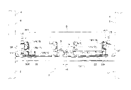
Fig. 1 is a plan view showing a stacker crane carrying an article
transfer device and an article storage rack,
Fig. 2 is a side view showing the stacker crane carrying the article
transfer device and the article storage rack,
Fig. 3 is a side view of a vertically movable platform carrying the
article transfer device,
Fig. 4 is a plan view of the vertically movable platform carrying the
article transfer device,
9
CA 02771322 2012-02-15
Fig. 5 is a cross-sectional rear view as seen along the arrows P-P in
Fig. 4,
Fig. 6 is a partial cross-sectional front view as seen along the arrows
Q-Q in Fig. 4,
Fig. 7 is a partially transparent view showing a centering
mechanism,
Fig. 8 is a vertical sectional side view showing a backside clamp unit
and a backside placement support portion, and
Fig. 9 is a plan view for describing an operating state of the pair of
clamp portions.
[MODES FOR CARRYING OUT THE INVENTION]
[0030]
An embodiment is described next in which an article transfer device
in accordance with the present invention is incorporated in a stacker crane
in an automated warehouse with reference to the drawings.
[Automated warehouse]
As shown in Fig. 1 and Fig. 2, the automated warehouse is provided
with two storage racks 1 which are installed such that they are spaced
apart from each other and such that their respective directions along which
articles are moved in and out are opposite from each other, and a stacker
crane A which runs along a work path formed between the storage racks 1.
[0031]
[Storage rack]
Each article storage rack 1 includes a plurality of support columns
la that stand vertically and are spaced apart from each other in a rack
lateral width direction (direction along W in Fig. 1) and in a rack fore and
aft
direction (direction along F in Fig. 1), and article support boards lb that
span between a plurality of the support columns la arranged in the rack
lateral width direction. And the article storage rack 1 is configured to store
a plurality of articles with the articles B being received and supported by
the article support boards lb and with a plurality of storage locations for
storing articles B being arranged or layered in the rack lateral width
direction as well as in the rack vertical direction.
CA 02771322 2012-02-15
[0032]
Provided to each article support board lb is a plurality of storage
locations each of which functions as a location for storing one article B and
each of which is defined at every predetermined interval along the rack
lateral width direction. Although there are two or more kinds of articles B of
different size as described below, articles B having the same or
approximately the same width in the rack lateral width direction are
arranged in the rack lateral width direction W on each article support board
lb. In addition, each of the articles B stored in the storage locations is
arranged such that its side face on the front face side of the rack (i.e.,
side
face that faces the work path) is in alignment with the side faces of other
articles with respect to the rack fore and aft direction F (see Fig. 1). The
article storage rack 1 is, thus, configured to store two or more kinds of
articles B having different lengths L in the article lateral direction which
extends along the rack lateral width direction W.
[0033]
[Articles]
Two or more kinds of articles B of different size exist with the lateral
length varying from the maximum lateral length Lmax (for example, 1510
mm in the present embodiment) to the minimum lateral length Lmin (for
example, 335 mm in the present embodiment). Article length along the
article transfer direction (i.e., direction along the rack fore and aft
direction
F) is basically greater for articles with greater length L in the lateral
direction. Thus, the stacker crane A transfers two or more kinds of articles
B having different lengths in the article lateral direction which is
perpendicular to the article transfer direction.
[0034]
The articles B in present embodiment are preferably plastic
containers for storing parts for manufacturing devices, or work-in-process,
etc. General purpose plastic material, such as polypropylene (PP) and
polyvinyl chloride (PVC) or engineering plastic material, such as
polycarbonate (PC) and polyethylene terephthalate (PET) is used as the
material for the container. Although the rigidity of the container is high,
the
11
CA 02771322 2012-02-15
material used is not limited to these materials. And it is also possible to
use
metal as the material for the containers. In addition, ribs are formed in,
among other places, the bottom surface of the container to reinforce rigidity
so that it is not easily bent or otherwise deformed due to the weight of its
content during the transfer onto the article support board lb.
[0035]
[Stacker crane]
As shown in Fig. 1 and Fig. 2, the stacker crane A has a pair of
support columns 4 which guide and support the vertically movable
platform 3 such that the platform 3 can be moved vertically and which are
mounted to the traveling carriage 2 - which runs along a single travel rail 9
installed in the work path - at a front position and a back position
respectively in a crane travel direction along the rack lateral width
direction
W so that the support columns 4 are spaced apart from each other. The
upper end portions of the support columns 4 are connected to each other
by an upper frame 6 which is guided and supported by an upper guide rail
5 installed in the upper area of the work path.
[0036]
In addition, the traveling carriage 2 has, at a front position and a
back position in the crane travel direction with a distance therebetween,
travel wheels 10a and 10b which are supported by and roll on a top face of
the travel rail 9, and a pair of right and left guide rollers (not shown)
which
are located near the travel wheels 10a and 10b such that the guide rollers
press on the travel rail 9 from right and left directions and roll along the
side faces of the travel rail 9. The traveling carriage 2 further includes,
among other things, a travel electric motor M1 for actuating driving wheels
10a which are either the travel wheels 10a or the travel wheels 10b, a
control device 7 for controlling the stacker crane, a laser travel range
finder
(not shown) for detecting the travel position of the traveling carriage 2 in
the
work path by measuring the distance from a reference position defined on
the ground side, a laser vertical range finder (not shown) for detecting the
vertical position of the vertically movable platform 3 in the vertical
movement path, and an electric power collector (not shown) for receiving
electric power for the operation of the stacker crane. With such a
12
, CA 02771322 2012-02-15
configuration, stacker crane A is configured to travel automatically along
the travel rail 9 as it driven by the travel electric motor M1 while being
prevented from falling down sideways by the upper frame 6. Each of the
control device and a controller, etc. described in this specification includes
all or some of the components which a conventional computer has,
including a CPU, memory, a communication unit, etc. and has algorithms,
that are required to perform the functions described in this specification,
stored in memory.
[0037]
As shown in Fig. 3, Fig. 4, and Fig. 8, the vertically movable platform
3 includes a pair of vertical movement brackets 3F and 3R (front side
vertical movement bracket 3F and backside vertical movement bracket 3R)
which are guided by guide rail portions formed respectively in the pair of
support columns 4 and which are located at the front and back ends in the
crane travel direction. A frame 11 that functions as a vertically movable
platform main body is connected to the pair of vertical movement brackets
3F and 3R, and an article transfer device 14 for transferring an article B
between itself and a transfer target location is mounted on the frame 11.
That is, the stacker crane A includes the article transfer device 14.
[0038]
As shown in Fig. 5 and Fig. 7, the frame 11 of the vertically movable
platform 3 includes, among other things, a pair of main frames 12 that
extend along the crane travel direction and that are spaced
apart from each other in a crane lateral direction (right and left direction)
along the rack fore and aft direction F, and a plurality of connecting frames
13 that connect the mainframes 12 at three locations including a central
part and the front and back end portions in the crane travel direction. As
shown in Fig. 2, mounted at fore-and-aft central locations of the pair of
main frames 12 are on-rack article detection sensors 15 for detecting the
presence of an article currently in the storage location of the article
support
board lb to prevent two articles to be transferred to the same location, and
support board detection sensors 16, for detecting an end face of the article
support board lb that is on the side of the work path, so located that the
sensing directions point toward each of the pair of article storage racks 1.
13
CA 02771322 2012-02-15
[0039]
As shown in Fig. 2, a pair of vertical movement driving chains 8 are
connected to the pair of vertical movement brackets 3F and 3R so that the
pair of vertical movement brackets 3F, 3R and the frame 11 are suspended
and supported by them. The pair of vertical movement driving chains 8:
have one ends connected to upper portions of the pair of vertical movement
brackets 3F and 3R respectively; run over guide sprockets provided to the
upper frame 6, over a guide sprocket provided to one of the support
columns 4, and over driving sprockets (not shown) provided at one end of
the traveling carriage 2; and have the other ends connected to lower
portions of the pair of vertical movement brackets 3F and 3R. And the
vertically movable platform 3 is configured to be raised and lowered with
the feeding out operation and spooling operation of the vertical movement
driving chains by drivingly rotating the drive sprockets in one direction and
its opposite direction with the vertical movement electric motor M2.
[0040]
A ground side controller (not shown) which issues commands for
taking articles into and out of the racks is installed in one end area of the
work path for the stacker crane A. When a command to take an article
into a rack or out of a rack is issued from this ground side controller, the
control device 7 mounted in the stacker crane A controls the traveling
operation of the traveling carriage 2, the vertical movement operation of the
vertical movement carriage 3, and the transfer operation of the article
transfer device 14 based on detected information from various sensors
such as the laser travel range finder, laser vertical range finder, on-rack
article detection sensor 15, support board detection sensor 16. Thereby,
the stacker crane A performs a take-in transporting operation in which an
article B is transported from a take-in-and-out conveyer (not shown)
provided in an end portion of the article storage rack 1 to a storage location
defined on an article support board lb in an article storage rack 1, and a
take-out transporting operation in which an article B is transported from a
storage location defined on an article support board lb in an article storage
rack la to the take-in-and-out conveyer. In addition, the take-in
commands and the take-out commands are transmitted to the control
14
CA 02771322 2012-02-15
device 7 from the ground side controller by an optical transmission device
using infrared transmission. A control command issued by the control
device 7 concerning transfer control is transmitted to a control terminal
provided in the vertically movable platform 3 from the control device 7 by
an optical transmission device using infrared transmission.
[0041]
Details on the article transfer device 14 provided on the frame 11 of
the vertically movable platform 3 are described next.
[0042]
As shown in Figs. 2 to 4, the article transfer device 14 includes a
placement support portion 17 for receiving and supporting an article B to
be transferred, and a pair of clamp portions 18 consisting of a front side
clamp portion 18F and a back side clamp portion 18R that can be projected
and retrieved with respect to the placement support portion 17 along the
rack fore and aft direction (crane lateral direction) which is the article
transfer direction and that can be moved toward and away from each other
between gripping positions (positions along the crane travel direction
shown with solid lines in Fig. 9) in which the article B to be transferred is
gripped and releasing positions (positions along the crane travel direction
shown with imaginary lines in Fig. 9) spaced apart wider than the gripping
positions.
[0043]
The placement support portion 17 includes a front side placement
support portion 17F for receiving and supporting a front side portion, in the
crane travel direction, of the bottom surface of the article B to be
transferred and a back side placement support portion 17R for receiving
and supporting a back side portion, in the crane travel direction, of the
bottom surface of the article B to be transferred. That is, the placement
support portion 17 includes a pair of divided placement support portions
17F and 17R for separately receiving and supporting both side portions
(both side portions in the crane travel direction), in the article lateral
direction, of the bottom surface of the article B to be transferred. And since
only the both side portions, in an article lateral direction, of the article B
to
CA 02771322 2012-02-15
be transferred are supported by the pair of divided placement support
portions 17F and 17R in the present embodiment, the placement support
portion 17 consists only of the pair of divided placement support portions
17F and 17R.
[0044]
Each of the front side placement support portion 17F and the back
side placement support portion 17R can be moved along the crane fore and
aft direction with respect to the main frame 12 of the frame 11 of the
vertically movable platform 3. That is, in the present embodiment, the base
platform to which the pair of divided placement support portions 17F and
17R are provided is the frame 11 of the vertically movable platform 3.
[0045]
As shown in Fig. 3 and Fig. 4, each of the pair of divided placement
support portions 17F and 17R have a plurality of rotary rollers 21 which
can rotate about laterally extending axes (axes extending in the horizontal
direction and in the rack lateral width direction W, i.e., the crane travel
direction) arranged along the article transfer direction.
[0046]
To describe in more detail, taking the front side placement support
portion 17F shown in Fig. 6 as an example, a plurality of the rotary rollers
21 are arranged in the article transfer direction with both ends of the pivot
shafts 21C rotatably supported by a pair of roller support plates 22 that are
spaced apart from each other in the direction that is perpendicular to the
article transfer direction and that are long in the article transfer direction
(see Fig. 8). Arranged below the plurality of rotary rollers 21 is a conveyor
driving belt 23 that contacts the lower part side portion of all the rotary
rollers 21 except the two rotary rollers 21, i.e., a left end roller 21L and a
right end roller 21R which are located in either end in the article transfer
direction. A plurality of pressing rollers 24 for pressing the conveyor
driving
belt 23 into reliable contact with the lower part side portion of the rotary
rollers 21 are provided along the article transfer direction and within the
loop of the conveyor driving belt 23. And a tension roller 25 for adjusting
the tension of the conveyor driving belt 23 is provided outside of the loop of
16
CA 02771322 2012-02-15
the conveyor driving belt 23.
[0047]
And the conveyor driving belt 23 is moved over the rollers by
drivingly rotating the conveyor motor M3 to drivingly rotate the driving
roller 26, which drivingly rotate the plurality of rotary rollers 21
simultaneously. In addition, as for the two rotary rollers 21, namely the left
end roller 21L and the right end roller 21R, a rotary roller 21 located next
to
the respective one of the two rotary rollers 21 is connected directly to the
respective one by a transmission belt 27 so that a rotational force is
transmitted from the rotary roller 21.
[0048]
As shown in Figs. 5, 6, and 8, the conveyor motor M3 and the
driving rollers 26 are attached below the pair of roller support plates 22 in
the front side placement support portion 17F and form a unit structure so
that they can move in unison with the front side placement support portion
17F. That is, the conveyor motor M3 which drivingly rotates all of the
plurality of rotary rollers 21 is provided to the front side placement support
portion 17F such that the motor M3 can move in unison with the front side
placement support portion 17F.
[0049]
While the front side placement support portion 17F is described
above, a conveyor motor M3 which can move in unison with the backside
placement support portion 17R is similarly configured to drivingly rotate all
of the plurality of rotary rollers 21 of the backside placement support
portion 17R. Thus, the conveyor motor M3 that functions as a roller
actuator for drivingly rotating all of the plurality of rotary rollers 21 is
provided to each of the pair of the divided placement support portions 17F
and 17R for movement therewith.
[0050]
The main frames 12 in the frame 11 of the vertically movable
platform 3 are rectangular pipes in a sectional view as shown in Figs. 5 and
6. And as shown in Figs. 3, 4, and 7, the guide rails 19 are located on their
17
CA 02771322 2012-02-15
top surfaces with each guide rail 19 divided into a forward portion and a
backward portion in the crane travel direction. That is, a front side guide
rail 19F is placed on the top surface of a front side area in the crane travel
direction of each of the pair of main frames 12 and a back side guide rail
19F is placed on the top surface of a back side area in the crane travel
direction of each of the pair of main frames 12. That is, a pair of front side
guide rails 19F and a pair of backside guide rails 19R are arranged forward
and backward in the crane travel direction on the frame 11 of the vertically
movable platform 3 with a total of four guide rails 19 provided thereon.
[0051]
As shown in Fig. 6, the front side placement support portion 17F is
mounted on a pair of front side base plates 31F which connect the lower
portion of the pair of roller support plates 22 at both end locations in the
article transfer direction, i.e., at locations above the pair of front side
guide
rails 19F. And a pair of front side slide blocks 30F that are guided by the
front side guide rails 19F are provided on each of the back surfaces of the
pair of front side base plates 31F such that the blocks 30F are spaced apart
from each other in the fore and aft direction. Therefore, the front side
placement support portion 17F is guided by the pair of front side guide rails
19F by means of a total of four front side slide blocks 30F attached under
the pair of front side base plates 31F to which the support portion 17F is
attached and which are located at both end locations in the article transfer
direction.
[0052]
Similarly, as shown in Fig 5, the back side placement support
portion 17R is guided by the pair of back side guide rails 19R by means of a
total of four back side slide blocks 30F attached under the pair of back side
base plates 31R to which the support portion 17R is attached and which
are located at both end locations in the article transfer direction.
[0053]
Thus, the front, back, right, and left front side slide blocks 30F of
the front side placement support portion 17F are guided by the pair of the
front side guide rails 19F, and the front, back, right, and left back side
slide
blocks 30R of the back side placement support portion 17R are guided by
18
CA 02771322 2012-02-15
_
the pair of the back side guide rails 19R. And the front side placement
support portion 17F and the back side placement support portion 17R are
synchronously moved in opposite directions by a centering mechanism 20
described below.
[0054]
Thus, the front side placement support portion 17F and the back
side placement support portion 17R can be moved between near positions
(approach limit positions) and spaced apart positions (spaced-apart limit
positions) within the limits of the movable range whose ends are defined by
the spaced-apart limit positions (positions of the front side placement
support portion 17F and the backside placement support portion 17R
shown with solid lines in Figs. 3 and 4) in which the front side placement
support portion 17F is located at a front side end location of the pair of
front side guide rails 19F and the back side placement support portion 17R
is located at a back side end location of the pair of the back side guide
rails
19R, and the approach limit positions (positions of the front side placement
support portion 17F and the back side placement support portion 17R
shown with phantom lines in Figs. 3 and 4) in which the front side
placement support portion 17F is located at a back side end location of the
pair of front side guide rails 19F and the back side placement support
portion 17R is located at a front side end location of the pair of the back
side guide rails 19R.
[0055]
And when the front side placement support portion 17F and the
back side placement support portion 17R are located at the approach limit
positions, the ends of the plurality of rotary rollers 21 provided to each of
the pair of divided placement support portions 17F and 17R are moved
close to each other to the positions in which the ends face one another. And
when the pair of divided placement support portions 17F and 17R are
located at the approach limit positions, the dimension Lg (for example, 45
mm in the present embodiment) - in the article lateral direction - of the gap
G formed between the pair of divided placement support portions 17F and
17R is smaller than the length Li (for example, 150 mm in the present
embodiment) - in the article lateral direction - of each of the the pair of
19
CA 02771322 2012-02-15
divided placement support portions 17F and 17R. Thus, the front side
placement support portion 17F and the back side placement support
portion 17R are configured to face each other in close proximity when they
are located at the approach limit positions which are limit positions in the
movable range that are closer to each other. The length Li, in the article
lateral direction, of each divided placement support portions 17F or 17R
may be defined as the dimension in the article lateral direction over which
each of the support portions contacts the bottom surface of the article, and,
for example, may be defined in the present embodiment as the length, in
the article lateral direction, of the rotary rollers 21. Therefore, the
article
transfer device 14 of the present embodiment is not constrained by any
central support for supporting the central location of the bottom surface of
the article B as is with an article transfer device having a conventional
structure; thus, the positions of the front side placement support portion
17F and the back side placement support portion 17R may be brought
sufficiently close together.
[0056]
Thus, with this article transfer device 14, both side portions of the
bottom surface of the article B can be supported by the front side
placement support portion 17F and the back side placement support
portion 17R by adjusting the positions of the front side placement support
portion 17F and the back side placement support portion 17R within the
movable range between the spaced apart limit positions and approach limit
positions depending on the length of the article in the lateral direction. And
even an article that is short in the article lateral direction and that could
not be transferred by a conventional device can be transferred by bringing
the front side placement support portion 17F and the back side placement
support portion 17R to the approach limit positions.
[0057]
As shown in Figs. 7 and 8, the centering mechanism 20 includes a
front side moving operation member 28F provided to connect the pair of
roller support plates 22 of the front side placement support portion 17F at
their lower portions, a back side moving operation member 28R provided to
connect the pair of roller support plates 22 of the bad l side placement
CA 02771322 2012-02-15
support portion 17R at their lower portions, a centering belt 29 that is
circulated along a circulating path set up horizontally and parallel to the
frame 11 of the vertically movable platform 3 and that moves the front side
moving operation member 28F and the back side moving operation member
28R in opposite directions to each other along the direction that is
perpendicular to the article transfer direction, a centering motor M4 for
driving and circulating the centering belt 29, a timing pulley 34T provided
to an output shaft of the centering motor M4, and a driven pulley 34S
arranged in the frame 11 at a location that is opposite the timing pulley 34T
in the direction that is perpendicular to article transfer direction.
[0058]
As shown in Figs. 5 and 7, each of the timing pulley 34T and the
driven pulley 34S is attached to a respective one of a pair of connecting
frames 13C for attaching the centering mechanism and spanning between
the pair of main frames 12 of the frame 11 by means of a bracket 39.
[0059]
As shown in Fig. 7, the front side moving operation member 28F and
the back side moving operation member 28R are fixed to one and the other
respectively of the two belt portions of the centering belt 29 that extend in
parallel to each other, by means of coupling members 32. Therefore, when
the centering belt 29 is circulated, the front side moving operation member
28F and the back side moving operation member 28R are moved in
mutually opposite directions; thus, the front side placement support
portion 17F and the back side placement support portion 17R move in the
mutually opposite directions while guided by the guide rails 19.
[0060]
Since the centering motor M4 drivingly rotates the timing pulley 34T
thereby circulating the centering belt 29 which consists of a timing belt that
meshes with this timing pulley 34T and the driven pulley 34S which is
located opposite the timing pulley 34T, the control device 7 described
above can control the near-each-other positions and the spaced-apart
positions of the front side placement support portion 17F and the back side
placement support portion 17R depending on the length, in the lateral
21
CA 02771322 2012-02-15
direction, of the article B by controlling the number of rotations of the
centering motor M4 based on length information of the article B in the
article lateral direction.
[0061]
Further, in the present embodiment and as shown in Figs. 3 and 6,
a front side clamp unit 35F described below and having a front side clamp
portion 18F is attached integrally by means of the clamp attachment
bracket 33 to the pair of front side base plates 31F to which the front side
placement support portion 17F is attached. Since the front side placement
support portion 17F and the front side clamp unit 35F are attached to the
same pair of front side base plates 31F, the front side clamp portion 18F is
also moved in unison with the front side placement support portion 17F
when the centering motor M4 is actuated to move the front side placement
support portion 17F.
[0062]
Similarly, as shown in Fig. 3 and Fig. 5, a back side clamp unit 35R
described below and having a back side clamp portion 18R is attached
integrally by means of the clamp attachment bracket 33 to the pair of back
side base plates 31R to which the back side placement support portion 17R
is attached. Since the back side placement support portion 17R and the
back side clamp unit 18R are attached to the same pair of back side base
plates 31R, the back side clamp portion 18R is also moved in unison with
the back side placement support portion 17R when the centering motor M4
is actuated to move the front side placement support portion 17R.
[0063]
Thus, each of the pair of clamp portions 18F and 18R and the
respective one of the pair of divided placement support portions 17F and
17R are connected to each other so that they can move in unison. And the
centering motor M4 functions both as a clamp actuator for moving the pair
of clamp portions 18F and 18R toward and away from each other and as a
placement support portion actuator for moving the pair of divided
placement support portions 17F and 17R toward and away from each
other.
22
CA 02771322 2012-02-15
[0064]
In addition, the centering motor M4 is controlled not only by
position control but by a torque control by the control device 7. This is
because the driving torque of the centering motor M4 is controlled in order
to control the gripping pressure when gripping the article B by the pair of
clamp portions 18F and 18R, in addition to controlling the near-each-other
positions and spaced apart positions of the pair of clamp portions 18F, 18R
and the pair of divided placement support portions 17F, 17R depending on
the length of the lateral direction of the article B. Such torque control
described in such this specification is performed through conventional
technology for a given type of motor, such as a control based on the
relationship between the applied direct current voltage or
alternating-current frequency and the rotation rate of the motor, or a
control using an encoder feedback, etc.
[0065]
The configuration of the pair of clamp portions 18F and 18R will be
described next, taking the back side clamp portion 18R as an example. The
back side clamp portion 18R is provided to the back side clamp unit 35R
connected to the pair of back side base plates 31R. The back side clamp
unit 35R includes a projecting-retracting operation portion 38 having a
three-stage slide fork 36 and a transmission gear mechanism 37, a fork
motor M5 for both projecting this projecting-retracting operation portion 38
in one direction and retracting it in the opposite direction, and the back
side clamp portion 18R which is attached to a primary fork of the slide fork
36 and is a plate-shaped member that is long in the article transfer
direction (direction along which the fork is projected and retracted), and
which has engaging claws formed at both ends for engaging corner portions
of the article B.
[0066]
[Control configuration]
The control device 7 controls the operation of the centering motor
M4 that functions as a clamp actuator as well as the placement support
portion actuator based on the length information in the article lateral
23
CA 02771322 2012-02-15
direction of an article B to be transferred. In addition, the control device 7
controls the rotation of the conveyor motor M3 which functions as a roller
actuator as well as the rotation of the fork motor M5 which functions as a
clamp projecting and retracting actuator, based on the end position
information, in the article transfer direction, of the article B to be
transferred and detected by out-of-bounds sensors S1 (see Figs. 5 and 7) or
a positioning sensor (not shown).
[0067]
When an article take-in command is issued from the ground side
controller, the control device 7 receives the position information along the
crane travel direction and the position information along the crane vertical
movement direction about the transfer location in the take-in-and-out
conveyer which is designated as the transport origin and a storage location
in the article storage rack 1 which is designated as the transport
destination as well as length information, in the article lateral direction,
of
the article B to be transferred, from the take-in command.
[0068]
In addition, when an article take-out command is issued from the
ground side controller, the control device 7 receives the position
information in the crane travel direction and the position information along
the crane vertical movement direction about a storage location in the article
storage rack 1 which is designated as the transport origin and the transfer
location in the take-in-and-out conveyer which is designated as the
transport destination as well as length information, in the article lateral
direction, of the article B to be transferred, from the take-out command.
[0069]
In addition, the transfer operation of the article transfer device 14 is
different depending on whether it is at the transport origin or is at the
transport destination and is either an unloading transfer (i.e., transfer for
delivering an article) or a scooping transfer (namely, transfer for receiving
the article). Therefore, when receiving the position information in the crane
vertical movement direction about the transport origin or the transport
destination from the take-in command or the take-out command, the
24
CA 02771322 2012-02-15
control device 7 is configured to receive position information which
indicates a position that is higher by a set height (for example, 30 mm),
when a command is issued specifying a storage location or a transfer
location as a transport destination where unloading transfer is to be
performed, than the position in the case where the command specifies a
storage location or the transfer location as a transport origin where a
scooping transfer is to be performed.
[0070]
The position information along the crane travel direction, and
position information along the crane vertical movement direction may be
given from the ground side controller directly to the control device 7
through command information. And position ID information may be given
in the command information from the ground side controller and the
control device 7 may acquire the position information by looking up a
position information table based on the position ID information. Similarly,
the length information in the article lateral direction may be given from the
ground side controller directly to the control device 7 through command
information. And article kind ID information may be given in the command
information from the ground side controller and the control device 7 may
acquire the length information in the article lateral direction by looking up
an article lateral length table based on the article kind ID information.
[0071]
A control action of the control device 7 is described next, taking an
example of a case in which an article take-in command is issued where a
certain article B is to be transported from a transport origin which is the
transfer location in the take-in-and-out conveyer to a transport destination
which is a storage location in the article storage rack 1. The following
description assumes that the stacker crane A was in a standby state until
the take-in command was issued.
[0072]
The control device 7 controls the operations of the travel electric
motor M1 and the vertical movement electric motor M2 based on detected
information from the laser travel range finder and the laser vertical range
CA 02771322 2012-02-15
finder in order to move the article transfer device 14 to the scooping
position (receiving position) at the transfer location in the take-in-and-out
conveyer specified as the transport origin in the take-in command. And
while the traveling operation and the vertical movement operation to the
transport origin are in progress, the operation of the centering motor M4 is
controlled based on the length information, in the article lateral direction,
of the article B to be transferred and obtained based on the take-in
command to move the pair of clamp portions 18F and 18R to the releasing
positions for the article B to be transferred. In the present embodiment, the
releasing positions are set to be such positions that the difference between
the distance between the pair of clamp portions 18F and 18R and the
length L, in the article lateral direction, of an article B to be transferred
(sum of the clearances formed in the article lateral direction) is smaller
than
the length or dimension in the article lateral direction of one of the pair of
divided placement support portions 17F and 17R. This allows the article B
to be received and supported accurately by the pair of divided placement
support portions 17F and 17R even when the center of the article B in the
article lateral direction deviates or is displaced somewhat from the center
of the pair of divided placement support portions 17F and 17R.
[0073]
When the article transfer device 14 is located at the scooping
position for the transport origin, an operation request information for the
take-in-and-out conveyer is transmitted to the ground side controller to
have the take-in-and-out conveyer operated toward the article take-in side,
after checking the presence of the article B to be transferred located at the
transfer location in the take-in-and-out conveyer based on the detected
information from the on-rack article detection sensor 15. Simultaneously,
the conveyor motor M3 of the front side placement support portion 17F and
the conveyor motor M3 of the back side placement support portion 17R are
caused to operate toward the article retrieving side. In addition, the
rotation
operating speed of the drive motor of the take-in-and-out conveyer and
the rotation operating speed of each conveyor motor M3 of the pair of
divided placement support portions 17F and 17R are controlled by the
control terminal of the take-in-and-out conveyer and the control device 7
such that the transporting speed of the article B as it is transported by the
26
CA 02771322 2012-02-15
take-in-and-out conveyer is in synchronization with, or matches, the
transporting speed of the article B as it is transported by the plurality of
rotating rotary rollers 21 provided to each of the pair of divided placement
support portions 17F and 17R.
[0074]
The positioning of the article B - that is transported from the
transfer location in the take-in-and-out conveyer over to the article transfer
device 14 of the stacker crane A by the transporting action of the
take-in-and-out conveyer and the pair of divided placement support
portions 17F and 17R - is controlled based on the combination of the
detected information from the out-of-bounds sensor S1 and the positioning
sensor such that the article's end face is located in an outward end of the
article transfer device 14 in the article transfer direction. That is, it is
determined which of the right and left article storage racks 1 with respect to
the crane travel direction of the stacker crane A, the storage location in the
article storage rack 1 as a transport destination specified in the take-in
command belongs to. If, for example, the transport destination is a storage
location that belongs to the left hand side article storage rack 1 with
respect
to the crane travel direction, then the mounting position of the article B in
the article transfer direction in the pair of divided placement support
portions 17F, 17R is controlled such that the right hand side face of the
article B with respect to the crane travel direction is located in the right
hand side end of the article transfer device 14. When unloading articles B to
the storage locations in the article storage rack 1 specified as transport
destinations, the articles B can be stored in the storage locations on the
article support board 1B with the side faces, on the side of the work space,
of all the articles B being in line or flush with one another, simply by
projecting the pair of clamp portions 18F, 18R by a fixed stroke regardless
of the size of the article B.
[0075]
When an article B to be transferred is fully received and supported
by the pair of divided placement support portions 17F, 17R, the centering
motor M4 is controlled in the torque control mode in order to switch the
pair of clamp portions 18F, 18R to the gripping position from the releasing
27
CA 02771322 2012-02-15
position. That is, taking advantage of the fact that the driving torque of the
centering motor M4 increases when the pair of clamp portions 18F, 18R are
moved to the gripping positions for gripping the article B from the releasing
positions, the centering motor M4 is kept rotating in the direction which
would move the clamp portions closer together from the state in which the
pair of clamp portions 18F, 18R are in the releasing positions while
maintaining the driving torque of the centering motor M4 at the target
torque that is set to be greater than the driving torque at which the pair of
clamp portions 18F, 18R can be moved: and the operation of the centering
motor M4 is stopped when it is determined that the pair of clamp portions
18F, 18R are located in the gripping positions when the rotation speed of
the centering motor M4 falls below a set reference value for determining
that the gripping has been achieved.
[0076]
When the article B to be transferred is fully received and supported
by the pair of divided placement support portions 17F and 17R, and the
pair of clamp portions 18F and 18R are in the retracted positions and in the
gripping positions in which the article B is gripped, the control device 7
controls the operations of the travel electric motor M1 and the vertical
movement electric motor M2 based on the detected information from the
laser travel range finder and the laser vertical range finder to move the
article transfer device 14 to the unloading position at the storage location
in
the article storage rack 1 specified as the transport destination.
[0077]
When the article transfer device 14 is located in the unloading
position at the storage location specified as the transport destination, and
after ensuring that no other articles B exist at the storage location in the
article storage rack 1 based on the detected information from the on-rack
article detection sensor 15, the control device 7 operates the fork motors
M5 of the front and back clamp units 35F and 35R by a set amount of
stroke to the projecting side toward the storage location to project the pair
of clamp portions 18F, 18R to push the article B into the storage location.
Simultaneously, the conveyor motor M3 in the front side placement
support portion 17F and the conveyor motor M3 in the back side placement
28
CA 02771322 2012-02-15
support portion 17R are cause to start operating in the side that would
cause the article be pushed into the storage location. In addition, similar to
the case of the scooping action, the rotation operating speed of fork motor
M5 and the rotation operating speed of each conveyor motor M3 of the pair
of divided placement support portions 17F and 17R are controlled by the
control device 7 such that the transporting speed of the article B as it is
transported by the pair of projecting clamp portions 18F, 18R is in
synchronization with, or matches, the transporting speed of the article B as
it is transported by the plurality of rotating rotary rollers 21 provided to
each of the pair of divided placement support portions 17F and 17R.
[0078]
In this manner, when the pair of clamp portions 18F and 18R are
located in the projected positions and when the article B to be transferred is
located in the storage location in the article storage rack 1 designated as a
transport destination as shown in Fig. 9, the centering motor M4 is
controlled in the position control mode to switch the pair of clamp portions
18F and 18R from the gripping positions shown with solid lines in Fig. 9 to
the releasing positions shown with imaginary lines in Fig. 9. That is, the
centering motor M4 is stopped after the centering motor M4 is operated by
a target drive amount in a move-apart direction to move the clamp portions
18F and 18R away from each other by a set operating amount for a grip
release operation from the state in which the pair of clamp portions 18F
and 18R are in the gripping positions.
[0079]
And when the pair of clamp portions 18F and 18R are in the
projected positions and in the releasing positions to release the grip on the
article B, the fork motors M5 in the front and back clamp units 35F, 35R
are operated in the retrieval direction to retract the pair of clamp portions
18F and 18R. Incidentally, the conveyor motor M3 in the front side
placement support portion 17F, and the conveyor motor M3 in the back
side placement support portion 17R may be left unoperated in this case.
[0080]
[Alternative Embodiments]
29
CA 02771322 2012-02-15
Alternative embodiments of the present invention are described
next.
[0081]
(1) In the embodiment described above, an example was described
in which the placement support portion includes only the pair of divided
placement support portions. However, the invention is not limited to this
example. For example, a placement support portion may be so configured
to have an intermediate support member that is narrow in the article lateral
direction for receiving and supporting an intermediate portion, in the
article lateral direction, in the bottom surface of an article. By providing
an
intermediate support member, the article can be reliably received and
supported by the placement support portion even where an article to be
transferred would be bent downward and change shape if it was supported
only by the pair of divided placement support portions, because the portion
in question of the article can be supported by the intermediate support
member.
[0082]
(2) In the embodiment described above, an example was described
in which the roller actuator drivingly rotates all of the plurality of rotary
rollers. However, the invention is not limited to this example. And some or
all of the rotary rollers may be configured as freely rotating rollers.
[0083]
(3) In the embodiment described above, an example was described
in which each of the pair of divided placement support portions is provided
with a plurality of rotary rollers which can rotate about laterally extending
axes arranged along the article transfer direction. However, the invention is
not limited to this example. For example, each of a pair of divided
placement support portion may consist of simply a pair of plate-shaped
members that receive and support an article.
[0084]
(4) In the embodiment described above, an example was described
in which the article transfer device was mounted on a stacker crane.
CA 02771322 2012-02-15
However, the invention is not limited to this example. For example, the
article transfer device may be mounted on an unmanned article carriage.
[0085]
(5) In the embodiment described above, an example was described
in which each of the pair of clamp portions consists of a plate-shaped
member that has a claw and that is projected and retracted by a
projecting-retracting operation portion. A so-called belt clamp type may be
used instead. That is, each of the pair of clamp portion may include an
article transporting endless revolving body that, in the gripping position,
contacts the lateral side of an article to be transferred and that is
circulated
about vertical axes. In this case, it is preferable to provide an circulating
actuator for driving and circulating the endless revolving body in each of
the pair of clamp portions such that the actuator can be moved in unison
with the clamp portion.
[0086]
Also, in this case, transporting means such as a roller conveyor etc.
may or may not be provided to the pair of divided placement support
portions. When a pair of divided placement support portions include
transport drive means such as a roller conveyor, etc. which is actuated by a
conveyor motor that functions as a transport drive device, the controller
may control the operations of the transport drive device and the circulating
actuator such that the transporting speed of the endless revolving body as
it is circulated is in synchronization with the transporting speed of the
transporting means in the pair of divided placement support portions.
[0087]
(6) In the embodiment described above, an example is described in
which each of the pair of clamp portions and the corresponding one of the
pair of divided placement support portion are connected to each other so
that they can be moved in unison and in which the clamp actuator
functions also as the placement support portion actuator. Instead, each of
the pair of clamp portions and each of the pair of divided placement support
portions may be configured such that they can be moved separately and
independently. And the clamp actuator and the placement support portion
31
CA 02771322 2012-02-15
actuator may be provided separately.
[Industrial Applicability]
[0088]
The present invention can be utilized in an article transfer device
used in a warehouse etc. and a stacker crane having the article transfer
device.
[Description of the Reference Numerals and Symbols]
[0089]
A Stacker Crane
M3 Roller Actuator
M4 Placement Support Portion Actuator, Clamp Actuator
G Gap
3 Vertically Movable Platform, Base Platform
7 Controller
17, 17F, 17R Pair of Divided Placement Support Portions
18, 18F, 18R Pair-of Clamp Portions
21 Rotary Roller
32