Note: Descriptions are shown in the official language in which they were submitted.
CA 02771524 2012-03-16
Reflector For Radiant Tube Heater
Background of the Invention
This invention relates to radiant tube heater systems and in particular
to reflectors for radiant tube heaters.
Radiant tube heater systems are well known in the heating industry and
are useful for warming large covered spaces such as those found at industrial
and manufacturing facilities, air craft hangers and swimming pools. However
there are some known and perceived problems with such heating systems
including insufficient heat being supplied to areas in which heat is needed
and
the non-uniform supply of heat to areas along the length of the tubular
conduit through which the combustion gases flow.
It is known to provide metal reflectors located directly above the radiant
tube and extending the length thereof in order to reflect the heat from the
tube downwardly towards the floor area of the building or structure where it
is
required. A low intensity tube heater generally comprises a burner attached
to a steel radiant tube. The sheet metal reflector extends over the top of the
tube and also over its two opposite sides. The reflector re-radiates and re-
directs infrared heat energy back to the tube, to the floor and to itself and,
in
this way, it reduces convection losses and directs more radiant heat to the
ground or floor where it is needed.
1
CA 02771524 2012-03-16
Most known low intensity infrared heaters have a radiant factor of 40%
to 45% and a convection heat output of 35% to 40%. Traditional radiant tube
systems have an inability to effectively control the convection and radiant
outputs. Radiant tube heaters for commercial and industrial space heating
systems can have a variety of firing rates ranging from, for example, 45,000
BTU/H to 200,000 BTU/H.
There is a need for better, more efficient radiant tube heaters having an
increased radiant factor and an improved heat flux density on the floor area.
By improving the efficiency of a radiant tube heater of the aforementioned
type, it is possible to reduce fuel consumption while still achieving a
comfortable temperature level and it is also is possible to reduce carbon
emissions.
According to one embodiment of the present invention, a reflector for
an elongate radiant tube heater having a single tubular conduit through which
hot fluid in the form of combustion gases flow comprises an elongate metal
reflecting member adapted to extend along the length of the tube heater and
to cover the top and two opposite sides of the tube heater in order to reflect
and disperse radiant heat waves from the tubular conduit. The reflecting
member includes two central panel portions meeting along a longitudinal
centerline of the reflecting member and forming an outwardly facing angle
ranging between 30 and 100 degrees. A bisector of the angle extends
substantially vertically and is vertically aligned with a centerline of the
tubular
2
CA 02771524 2012-03-16
conduit during use of the reflector on the radiant tube heater. The reflecting
member has further longitudinal panel sections extending outwardly and
downwardly from the central panel portions. The reflector includes a layer of
heat resistance insulation extending over an outer surface of the reflecting
member.
According to an exemplary version of the aforementioned reflector, the
outwardly facing angle formed by the central panel sections ranges between
45 and 80 degrees.
According to a second embodiment of the present invention, a radiant
heating apparatus for attachment to a burner for burning a heating fuel to
produce combustion gases includes an elongate tubular conduit through which
the combustion gases can flow and burn, one end of the conduit being
connectible to an outlet of the burner.
An insulated reflector extends
lengthwise along the tubular conduit and is positioned and shaped to reflect
and disperse radiant heat waves from the conduit during use of the apparatus.
The reflector has a longitudinal centerline located above and spaced from the
tubular conduit. The centerline divides the reflector into two half sections.
Each half section is formed with at least three longitudinal bends located
between the centerline and a respective bottom edge of the half section and
dividing the half section into at least four longitudinal reflecting portions
including a central portion. This central portion slopes upwardly from the
centerline during use of the heating apparatus. The central portions of the
3
CA 02771524 2012-03-16
two half sections form a central angle ranging between 30 and 80 degrees,
this angle facing away from the tubular conduit.
In an exemplary version of the aforementioned heating apparatus, the
reflective portions of each half section include a second reflecting portion
adjacent a respective one of the central portions and forming a second angle
in a transverse plane ranging between 100 and 135 degrees and facing
inwardly in the direction of the tubular conduit.
According to a third embodiment of the present invention, a radiant
tube heater system comprises a single tubular conduit through which hot fluid
including combustion gases flow and a plurality of support structures for
supporting the conduit at spaced locations along its length. The combustion
gases flow from one end to another end during use of the heater. An insulated
reflector extends lengthwise along the tubular conduit and is constructed and
shaped to reflect and disperse radiant heat waves from the conduit. The
reflector has a first longitudinal centerline located above a second
longitudinal
centerline of the conduit. The first longitudinal centerline divides the
reflector
into two similar half sections extending in opposite transverse directions
from
the centerline. Each half section is formed with three longitudinal bends
which
form obtuse angle facing inwardly towards the conduit. The bends of each
half section divide the half section into longitudinal reflecting portions
including a central portion that slopes upwardly from the first longitudinal
centerline during use of the heater system. The central portions of the two
4
CA 02771524 2012-03-16
half sections form an outwardly facing angle ranging between 30 and 100
degrees.
In one exemplary form of this tube heater system, the outwardly facing
angle is approximately 60 degrees and the reflector is constructed of bent
metal sheet and is insulated with ceramic insulation extending over the outer
surface of the reflector.
These and other aspects of the disclosed reflectors and radiant tube
heater systems will become more readily apparent to those having ordinary
skill in the art from the following detailed description taken in conjunction
with
the drawings.
So that those having ordinary skill in the art to which the present
disclosure pertains will more readily understand how to make the subject
invention, exemplary embodiments thereof will be described in detail herein
below with reference to the drawings, wherein:
In the drawings,
Figure 1 is a transverse, vertical cross-section of a reflector for a radiant
tube heater constructed in accordance with the invention, this view also
showing a radiant tube positioned within the reflector;
Figure 2 is a schematic cross-sectional view of a radiant tube heater in
use, this view showing an elongate laminar flame extending from a burner
5
CA 02771524 2012-03-16
head, a major portion of the radiant tube being omitted along with its
reflector
for purposes of this illustration;
Figure 3 is a transverse vertical cross-section of the reflector and
radiant tube of Figure 1 showing a hanger used to support both the reflector
and the tube;
Figure 4 is a schematic elevation showing a radiant tube heater
mounted above a floor and a rectangular enclosure used for measuring heat
flux at floor level, central portions of both the radiant tube and the
enclosure
being omitted;
Figure 5 is a schematic plan view of the enclosure of Figure 4 showing a
grid of side-by-side squares drawn or otherwise formed on the floor area;
Figure 6 is a side elevation of the reflector and radiant tube of Figure 1
mounted over a floor area;
Figure 7 is a schematic illustration illustrating how heat flux readings
were taken at different heights from the floor for determining maximum and
minimum heat flux readings over the floor area;
Figure 8 is a schematic perspective view illustrating a water cooling
system for a heat flux sensor used to measure heat flux on the floor area;
Figure 9 is a vertical cross-section of a prior art radiant tube heater and
reflector;
6
CA 02771524 2012-03-16
Figure 10 is a vertical cross-section of an inner reflector having a
central, outwardly facing angle of 80 degrees;
Figure 11 is a vertical cross-section of an inner reflector having a
central, outwardly facing angle of 120 degrees;
Figure 12 is a vertical cross-section of an inner reflector having a
central, outwardly facing angle of 160 degrees;
Figure 13 is a vertical cross-section of an inner reflector having a flat
central panel section and no central angle;
Figure 14 is a graphical depiction of heat flux readings taken using the
reflector of Figure 1, the height of the radiant tube being 18 feet above
floor;
and
Figure 15 is a graphical depiction of heat flux readings taken using the
reflector of Figure 1, the height of the radiant tube being 14 feet above
floor.
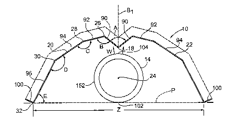
Shown in Figure 1 is a transverse vertical cross-section of a reflector 10
for an elongate radiant tube heater such as the heater 12 illustrated
schematically in Figure 2 which does not show the reflector extending above
and around the two opposite sides of its radiant tube 14. The tube 14 is an
elongate tubular conduit through which hot fluid in the form of combustion
gases flow, these gases being indicated at 16. The reflector is insulated with
a
heat resistant layer of insulating material. This insulating material can
withstand the high temperatures produced by the radiant tube. The reflector
7
CA 02771524 2012-03-16
includes an elongate, metal reflecting member adapted to extend along the
length of the radiant tube 14 in order to reflect and disperse radiant heat
waves from the radiant tube. The reflector has a longitudinal centerline which
can be referred to as a first longitudinal centerline 18 that divides the
reflector
into two similar half sections 20 and 22. These half sections extend in
opposite transverse directions from the longitudinal centerline 18 which is in
normal use located above the longitudinal centerline 24 of the radiant tube
14.
This centerline may be identified as the second longitudinal centerline of the
radiant tube heater. In the illustrated exemplary embodiment each half
section of the reflector is formed with several longitudinal bends each of
which
forms an obtuse angle facing inwardly towards the tubular conduit. In the half
section 20, these bends are indicated at 26, 28 and 30. In addition to these
bends, there is a central bend where the two half sections meet. This bend is
at the centerline 18.
Optionally, in an exemplary embodiment there is a further bend 32
located at each of the two bottom ends of the half sections. The illustrated
bend 32 forms a 90 degree angle, this angle facing generally upwardly and
outwardly. The exemplary reflector is made of a highly reflective metal, at
least on its inner reflecting surface, two suitable metals being aluminized
steel
sheet metal and Feran.
8
CA 02771524 2012-03-16
A standard exterior diameter of the radiant tube is four inches and the
length of the tube varies depending upon the particular job requirements but
can arrange for example from 25 to 70 ft or more.
With reference now to Figure 2, this figure illustrates a radiant tube
heater constructing in accordance with United States Patent No. 7,931,683
dated March 29, 2011, the description and drawings of which are incorporated
herein by reference. In Figure 2 only an upstream portion of the radiant tube
14 is shown for ease of illustration. The radiant tube can comprise several
sections arranged end to end as is well known to those skilled in the heating
art. The tube is heated by the flame and combustion gases to emit infrared
radiant heat which is reflected downwardly to the floor area or objects below
the heater by the reflector 10. Shown in Figure 2 is a gas valve governor or
gas valve unit 34 for the heater which connects to one end of a gas pipe 36.
This pipe extends to a burner nozzle 38 and a burner head 40 mounted on the
nozzle. The heater system also includes a blower or blower fan 42 having a
side air inlet 44 into which external air is drawn. The blower has an outlet
section which extends tangentially relative to the blower fan and which is
connected to the upstream end of the radiant tube or tubular conduit 14.
The burner head 40 is mounted within the tube and is adapted for
mixing combustible gas and for delivering the resulting mixture into an
upstream end section of the tubular conduit as shown. The burner head is
generally annular and has a cylindrical inlet portion 46 and a wider
cylindrical
9
CA 02771524 2012-03-16
outlet portion 48. The heater can be provided with natural gas or LPG gas
indicated by the arrow G taken from a suitable source and delivered through
the gas valve unit 34. Combustion air enters through vents or pores
distributed about the periphery of inlet portion 46. The mixture exiting from
the burner head 40 is ignited by an ionization electrode 50 so as to produce a
long laminar flame that extends substantially the length of the radiant tube.
The preferred material for the radiant tube 14 is stainless steel or
aluminized
steel, at least for an upstream section thereof that surrounds the hottest
part
of the flame and the burner head. The remaining downstream section can be
cold rolled steel.
Figure 6 schematically illustrates a radiant tube heater system indicated
generally by reference 54. Figure 6 illustrates how the reflector 10 extends
along the length of the radiant tube 14. Located at the upstream end of this
tube is the aforementioned heater 12. It will be appreciated that exhaust
gases exit through the downstream end 56 of the tube through a suitable
exhaust pipe which can deliver the gases to atmosphere. The radiant tube
heater is designed and constructed to provide heat to a generally rectangular
floor area indicated at 60. This floor area can, for example, be the floor of
and
industrial or commercial facility, usually a facility having a relatively high
ceiling which may render other forms of heating impractical or inefficient.
Both the radiant tube and its reflector 10 can be hung from a ceiling or
roof trusses with the use of a series of hangers 62, one of which is
illustrated
CA 02771524 2012-03-16
in Figure 3. These hangers can be made from bent metal rods or wires in a
manner known per se. The illustrated hanger 62 has a central, top loop 64
which can be attached to the end of a chain or hanging wire extending from
the ceiling. Sloping downwardly from opposite sides of the center loop are a
bent arm 66 and a shorter arm 68 which forms an end loop at 70. The hanger
includes a bottom section which has a substantially U-shaped central portion
72 sized to receive the radiant tube 14 as shown. The bottom section of the
hanger also includes two bent connecting sections 74, 76 that are integrally
connected to the central portion 72 and that extend respectively to bottom
ends of the hanger. The two bottom ends 78, 80 of the hanger are sized and
adapted to support the two bottom edges of the reflector as shown. Extending
upwardly from the bottom edge 80 is a resilient end section 82 which has a
hook 84 at its upper end. After the hanger is mounted around both the tube
and the reflector, the hook 84 is inserted through the end loop 70 so that the
hanger forms a complete loop able to support the tube and the reflector from
a ceiling or roof of a building or other structure.
In order to develop an improved, efficient reflector for a radiant tube
heater, a method has been developed for accurately measuring the heat flux
from a radiant tube heater at floor level using a special water-cooled heat
sensor. This sensor, its method of cooling and the measuring method for
determining the heat flux along the length of a radiant tube heater are
explained hereinafter. Using these accurate measurements of heat flux
emitted by a radiant tube heater and computational fluid dynamics (CFD) a
11
CA 02771524 2012-03-16
substantially improved reflector for a radiant tube heater has been developed
and one embodiment is illustrated in Figure 1. An important aspect of this
reflector is the central outwardly facing angle indicated at A. Each half
section
of the reflector includes a central reflecting portion that slopes upwardly
from
the first longitudinal centerline 18 during the use of the heater system. The
angle A formed by the central portions of the reflector ranges between 30 and
100 degrees. A particular exemplary range for the outwardly facing angle A is
between 45 and 80 degrees and in one particular exemplary embodiment, the
angle A is approximately 60 degrees. It will be appreciated that with the
central reflecting portions 90 extending at the indicated angle to the
horizontal
plane, they effectively reflect and radiate the heat waves indicated by the
arrows W that are radiating from the top of the radiant tube. Instead of being
reflected back towards the radiant tube, they are to an extent either
reflected
downwardly towards the floor area or towards one of the outer reflecting
portions of the reflector.
In the exemplary illustrated reflector, there are the aforementioned
three bends 26, 28 and 30 formed in each half section. Located adjacent to
the central portion 90 is a second reflecting portion 92. Adjacent this second
longitudinal portion and located outwardly there from is a third reflecting
portion 94 which, as shown, can be wider than the second reflecting portion.
Furthermore adjacent the third reflecting portion and sloping outwardly and
downwardly therefrom is a fourth reflecting portion 96 which extends to one
bottom edge of the reflector. The first longitudinal bend 26 is formed between
12
CA 02771524 2012-03-16
its respective central portion 90 and the adjacent second portion 92. The
second longitudinal bend is formed between the second reflecting portion 92
and the third reflecting portion 94 while the third longitudinal bend is
formed
between the third reflecting portion 94 and the fourth reflecting portion 96.
In
an exemplary version of the reflector, the size of the inner angle at the
first
longitudinal bend 26 is at least 110. In an exemplary version of the
reflector,
the inwardly facing angle B ranges between 105 and 140 degrees. Each of the
angles at B, C and D are dependent to a degree on the width of the adjacent
reflecting portions of the half section. The inner angle C at the second
longitudinal bend 28 in the exemplary reflector is at least 150 degrees and in
the illustrated exemplary embodiment is 160 degrees. In an exemplary
version of the reflector, the angle C ranges between 150 and 170 degrees, the
angle C being the angle facing inwardly in the direction of the tubular
conduit
or radiant tube. In one particular exemplary embodiment of the reflector
illustrated in Figure 1, the width of the central reflecting portion 90 on
each
half section is 1.42 inches while the width of the second reflecting portion
92
is 1.77 inches. Also in this embodiment the width of the third reflecting
portion 94 is 2.83 inches while the width of the fourth reflection portion 96
is
substantially larger at 3.9 inches. The overall width of the open bottom of
the
reflector indicated by Z in Figure 1 in this exemplary embodiment is 14.18
inches. Radiant tube heaters in general are known to have a radiant tube
having an external diameter of about four inches and a reflector that ranges
in
width between 12 and 15 inches.
13
CA 02771524 2012-03-16
Turning to the inner angle D formed between the third reflecting portion
94 and the fourth reflecting portion 96 and located in a transverse plane
relative to the longitudinal center axis of the radiant tube, an exemplary
range
for this angle is between 140 and 160 degrees and the illustrated exemplary
angle D is 150 degrees. The angle E formed between the horizontal plane and
the fourth reflecting portion 96 can vary and depends to a degree on the size
of the angles B, C and D. Typically this angle is about 65 degrees. If
desired,
a short edge flange 100 can be provided along the two opposite longitudinal
bottom edges of the reflector. One function of these flanges is to avoid a
sharp metal edge at the bottom edges of the reflector thereby making it easier
to handle and install.
Although the width of each of the reflecting portions that extends
longitudinally along each half section can vary to a degree, based on the
diameter of the radiant tube being about 4 inches, an exemplary version of
the reflector 10 has a central reflecting portion 90 with a transverse width
of
at least 1.3 inches while the transverse width of each of the second and third
reflecting portions 92, 94 is at least 1.70 inches.
As illustrated in Figure 1, during normal use of the present reflector
over a radiant tube which extends horizontally, a bisector of the angle A
indicated by the line B1 extends in a vertical plane extending along the
centerline of the radiant tube. Thus the bisector B1 is vertically aligned
with
the longitudinal centerline 24 of the tubular conduit.
14
CA 02771524 2012-03-16
In general, it is preferred that the radiant tube 14 be not only covered
by the reflector over its top side but also on the vertically extending sides
of
the tube as shown. The illustrated tube heater 14 has a bottom or bottom
extremity at 102 and this bottom is aligned approximately with a horizontal
plane indicated at P defined by the two opposite bottom edges of the
reflector.
In the illustrated reflector these bottom edges are formed by the reflector
bends at 32. Also shown in Figure 1 is a gap or space between the top or top
extremity 104 of the tube and the longitudinal centerline 18 of the reflector.
In an exemplary embodiment this gap is about 0.6 inches.
The improved reflector for a radiant tube heater described above is able to
provide a better radiant factor based on net calorific value. The reflector
for
the radiant tube heater has an effect on the radiant factor on the basis of
the
following factors:
1) Shape and construction of the reflector shield including the central bend
angle at 18;
2) The material from which the reflector is made, for example a highly
polished metal such as Feran reflects more radiant heat to the ground
or floor;
3) Reflector coverage area around the radiant tube; and
4) Insulation used on the reflector.
CA 02771524 2012-03-16
As far as insulation is concerned, the insulation that can be used on the
present reflector is a layer of ceramic insulation that extends over the outer
surface of the reflector and that is able to withstand the relatively high
temperatures created at the reflector by the radiant tube heater, including
the
highest temperatures generated along the length of the tube.
Measuring Heat Flux Generated By Radiant Tube Heater With Reflector
In order to develop and test the above described, improved reflector for
a radiant tube heater, it was necessary to develop an accurate system and
method for measuring the heat flux generated by the radiant tube heater at
floor level. Figures 4, 5 and 8 illustrate schematically a new system and
method for measuring heat flux from such a heater using a heat flux sensor,
the temperature of which can be carefully controlled during the measurement
process. In addition this new method measures the surface tube
temperatures accurately across and along the radiant tube heater at regular
intervals along the radiant tube. With reference to Figure 4, there is shown a
radiant tube heater system indicated generally at 110 and shown without the
reflector of the invention for illustration purposes. This system includes an
elongate radiant tube 112 having a distal end at 114 and a natural gas burner
and blower combination 116 at an upstream end. The radiant tube is shown
as having indefinite length and can, for example, be 30 ft., 50 ft. or 70 ft.
in
length. Although the hangers are not shown, it will be understood that the
radiant tube heater including the combination burner/blower are suspended
16
CA 02771524 2012-03-16
from a ceiling of the building in which the heat flux measurements are carried
out. Extending the length of the radiant tube 112 and arranged on the floor of
the building is a test enclosure 118. The floor 120 on which the enclosure
rests can be a finished concrete floor like that found in many industrial
buildings. The length of the enclosure indicated at L can correspond
substantially to the length of the radiant tube but it can also be shorter
than
the tube (extending only below the hotter sections of the tube). In one set of
experiments conducted by the applicants, the radiant tube measured 50 ft. in
length as did the distance L of the enclosure and the horizontal width of the
enclosure was 65 inches but the width of the heat flux measuring area can be
extended if desired. The enclosure has two end walls indicated at 122 and
124 in Figure 5 and two long side walls 126, 128. The height of these walls
can vary but, in the exemplary measuring system used by the applicants the
height was about 3 ft. The enclosure walls were made of cardboard panels but
other materials such as wood or plastic panels could also be used. The
function of the enclosure is to prevent undesirable air currents in the region
of
the floor that is surrounded by the enclosure. These currents could be caused
by persons walking near to measurement area for example. Although the
height could be somewhat higher than 3 feet, it should not be too high as the
heat generated by the tube heater must be able to escape from the enclosed
area.
The rectangular measurement plane indicated at 130 was divided into a
grid of squares arranged side by side and drawn or painted on the
17
CA 02771524 2012-03-16
measurement area. These measurement squares are indicated at 132. The
actual size of these squares is dependent upon the horizontal measurements
of the heat sensor used for the heat flux measurements, this substantially
square sensor being indicated at 134 in Figure 5. The particular sensor used
by the applicants was a type GHT-1C geothermal heat flux transducer
available from International Thermal Instrument Company of Delmar,
California and its horizontal measurements are 6 inches by 6.5 inches and the
sensor has a standard height of 0.225 inch. As explained hereinafter, the
sensor is modified to provide for water cooling of the sensor. In order to
measure the heat flux over the entire measurement plane 130, it was
necessary to move the sensor 134 sequentially from one square to the next
beginning, for example at the measurement square 132' in one corner of the
plane. The arrows at the bottom of Figure 5 illustrate how the sensor was
moved transversely across the measurement plane from the corner square
and then, after heat flux measurements have been taken at each square in the
row, the sensor is moved up to the adjacent transverse row indicated at 136.
The exemplary heat sensor that was used has a range of 1 millivolt to
1,200 millivolts and measures the local heat flux in one direction with the
results being expressed in watts per square meter. The sensitivity of the
sensor 134 that was used is 1.1 watts/m2 per 1MV and it operates in
temperatures ranging from -100 F to 250 F. The DC signal generated by the
transducer is conducted to the readout instrument by means of a waterproof
cable. Upon obtaining thermal equilibrium with its surroundings, the sensor
18
CA 02771524 2012-03-16
develops a voltage which is directly proportional to the local heat flux. The
principle of operation of this exemplary sensor is that the flow of heat
through
the transducer creates a minute temperature difference between its surfaces.
A multi-element, semi-conductor thermopile consisting of hundreds of Bi/Te
elements generates a DC voltage via the Seebeck effect. The resulting signal
is directly proportional to the heat flux through the transducer.
Although initial heat flux measurements were taken by placing the
sensor directly on the floor, it was found that the millivolts readings
fluctuated
significantly at a selected location because the floor acts as a heat storage
reservoir, and once it is heated, the floor will give off heat by radiation to
the
surroundings. The sensor was later tested by mounting it on a small wood
panel but again some fluctuations in the readings at the selected location
were
observed. This difficulty was overcome by modifying the sensor so as to
provide cooling by circulating water through the lower or bottom part of the
sensor at a substantially constant temperature by means of a pump. In order
to provide for water cooling, the aforementioned heat sensor was modified by
the addition of grooves and channels adjacent its bottom side through which
water can circulate. Two water nipples were added to the sensor so as to
provide an inlet and outlet for the water and these nipples were attached to
plastic hoses.
This set-up is illustrated schematically in Figure 8 wherein the two
hoses are indicated at 138 and 140 and a water pump is indicated at 142. The
19
CA 02771524 2012-03-16
submersible pump was placed inside a small reservoir such as a pail indicated
at 144. The water temperature in the reservoir was kept constant at 69 F
either by use of an ice pack or by adding cold water. The water temperature
was measured carefully using 12 type K thermocouples divided into three sets
of 4 thermocouples.
One set was located at the bottom of the water
reservoir, the second set at mid-height in the water and the third set just
below the surface of the water. The four thermocouples of each set were
connected in parallel and the two free ends of each couple were connected to
a Fluke thermometer to read the water temperature.
* 10
For purposes of heat flux measurement, it was also necessary to
measure accurately the surface tube temperature of the radiant tube heater
and type K thermocouples were used for these measurements, these
thermocouples being indicated at 150 In Figure 4. There thermocouples were
placed at one foot intervals along the length of the tube heater. Thus, in the
case of the radiant tube having a 70 ft. length, 210 thermocouples were used.
At each one foot interval, there was one thermocouple mounted at the top of
the tube (indicated at 104 in Figure 1), one thermocouple mounted at the
bottom extremity of the tube (indicated at 102), and a third thermocouple was
located at mid-height along one side of the tube, this position indicated at
152
in Figure 1. The thermocouples were attached to the surface of the tube using
stainless steel pipe clamps. It will be appreciated that because of driven-
flame buoyancy, a radiant tube heater generally has a higher tube
temperature at the top of the tube and a lower tube temperature at the
CA 02771524 2012-03-16
bottom of the horizontal tube. Theoretically and in practice, the temperature
at mid-height of the tube falls between the top surface tube temperature and
the bottom surface tube temperature.
In addition to measuring the surface temperature along the length of
the radiant tube, it is also necessary to measure the ambient temperature of
the air in the vicinity of the tube. The ambient temperatures were monitored
by three thermostats placed along the length of the radiant tube heater,
namely in the region of the first tube section located adjacent the burner,
the
middle section and adjacent the outlet or distal end of the radiant tube. In
one exemplary set up for heat flux measurements the first thermostat was
positioned about three feet away from the burner and the hot end of the
radiant tube, the second thermostat was located five to seven feet away from
the middle of the radiant tube while the third thermostat was about three feet
from the distal or outlet end of the radiant tube. The three thermostats were
used to calculate an average temperature which was then used to establish a
boundary condition for the CFD software simulation of the heat flux measuring
process. (see below)
In order to measure the voltage induced by the heat sensor 134 at each
location on the grid, a voltmeter was used. An exemplary voltmeter that can
be used is a Fluke-289, a precise and calibrated voltmeter having an accuracy
within 10 to 15 millivolts and a precision of 1 microvolt. The readings from
this voltmeter were taken after the surface tube temperature of the radiant
21
CA 02771524 2012-03-16
tube heater reached a steady state. It was found that the steady state can
easily be obtained from one half to one hour from burner start up. The
achievement of this steady state condition was ensured by the above
described taking of measurements of the radiant tube surface temperature
and checking to confirm that the measurements did not change with time.
The millivolts readings were allowed to fluctuate within 2% according to the
manufacturer's specifications but the readings rarely fluctuated more than 3%
of the average reading's value. If the fluctuations were very large and
continued for a relatively long time, the measurements were stopped and the
sources of error were investigated. It was found that possible sources of
error
in the heat flux readings include a change of ambient temperature, people
passing close to the measurement area, environmental radiation, and
excessive noise in the area of the measurement squares. To eliminate the
possible effect of dust and debris on the tube and reflector, a vacuum cleaner
and gauze were used to clean and wipe the tube and reflector twice a week.
To avoid any fouling or scaling inside the grooves/channels of the heat flux
sensor 134, in the hoses or in the pump, filtered water was used and changed
daily. Any windows in the measurement area were covered with shutters to
avoid sunlight hitting the enclosed area.
Calculation of Heat Flux Employing CFD Software
In order to validate the heat flux measurements taken using the above
described measuring method computational fluid dynamics (CFD) software
22
CA 02771524 2012-03-16
was used to compute the theoretical heat flux on a floor area corresponding
to that used for the actual heat flux measurements. In order to use this
software a number of parameters pertaining to the tube-reflector system
were determined. One of these considered as an operating variable for the
computer program was the height of the RTH above the floor area which is
set initially at 100 inches corresponding to the actual height of the RTH
using
the measurement method described above. Maximum average values of
numerical simulation results of the tube-reflector assembly were determined
for heights of 14 feet and 18 feet and these values are set out in Tables 1
and
2 below. In the CFD numerical study, the effects of minor parts of the RTH
such as clamps, screws, wire hangers and hanger plates were eliminated.
This study used seven interpolation functions (see below) each for a
respective one of seven 10 foot sections of the radiant tube and generated by
Table 3D Curve software and these functions were used to approximate the
tube temperature along each 10 foot length. The numerical results of heat
flux were calibrated with the experimental data which was affected by slight
changes of ambient temperature, material emissivity, environmental radiation
and local meshing settings.
The temperature of the radiant tube was taken at a steady state
condition and this temperature acted and served as boundary conditions for
the simulation code. Although the flow simulation software can accommodate
data from a few points, because the data points were in the order of 100 or
more, it was necessary to use an analytical function. The obtained data was
23
CA 02771524 2012-03-16
fed into the Table 3D Curve program in order to generate the corresponding
interpolation functions. The experimental readings based on the above
mentioned heat flux measuring method employing a heat flux sensor were
compared to the numerical results produced by the CFD software for radiant
tube height at 100 inches. The comparison between the experimental data
and the generated numerical values produced by the analytical functions
showed a definite correlation with the correlation percentage being between
97 and 98%.
The interpolation functions for a 200K Btu/H radiant tube heater (70
foot tube length) were determined to be the following:
Function 1:
(321.38889+389.31365*z-74.8053*z^2+6.3272*z^3-
0.21047*z^4+878.08013*theta-
1176.311451*thetaA2+396.82725*theta^3+32.11088*theta^4-
21.27832*theta^5).
Function 2:
(63152.09708-21477.29034*z+2935.88384*z12-
198.421465*z^3+6.620202031*z^4-0.087222222*z^5+56.30573*theta-
5.760882794*theta^2).
Function 3:
(1279.412121-39.53914141*z+70.31847134*theta+0.53156565656*z^2-
3.63097894438*theta^2-1.08280254777*z*theta).
24
CA 02771524 2012-03-16
Function 4:
(151787.528972015-17354.547916896*z+746.039478681*z1\2-
14.233974309*z^3+0.101641414*z^4+22.292993631*theta).
Function 5:
(91499.670070302-8137.9256710687*z+273.631019897*z^2-
4.097060320*zA3+0.023018648*z^4+20.636942675*theta-
1.014239929*theta^2).
Function 6:
(627.8227272727-2.4744949495*z+35.8656629994*theta-
0.0391414141*z^2-1.8864862672*theta^2-0.2451264235*z*theta).
Function 7:
(-434.6960678210+28.2928932179*z+94.0109695683*theta-
0.2640692641*z^2-1.8256318715*theta"2-1.1093418259*z*theta).
It should be understood that function 1 is used for the first 10 ft length
of the radiant tube and each of the subsequent functions is used for
respective one of the following six ten foot sections of the tube.
[0043]
The problem of determining leaving and net radiant heat fluxes is
solved using a discrete Monte Carlo method. This numerical method solves
the following radiative transfer equation (RTE) in steady state:
,
fidl, 01 rick
+-4r+ a, = + )1 + kib + _______ 01, min
CA 02771524 2012-03-16
The first term of the above equation represents the spatial distribution
of the radiant intensity, /, and the subscript A is to designate that each
quantity in the RTE is taken as a function of the wavelength. The variables K
and 6 represent the medium absorption and extinction coefficients. p, 4-, and
77
are the directional cosines that describe the direction of the radiant
intensity.
0 is the scattering phase function which is equal to 1 in isotropic
scattering.
By numerically solving the above RTE equation, one can find the radiant
intensity, /, at any point, wavelength, and direction in the enclosed area.
This
approach does not require calculation of view factor which is cumbersome in
some cases. The above RTE does not have an analytical solution for most
cases because of the complicated directional and spectral nature of thermal
radiation exchange between solid objects of various complex 3D shapes.
The Monte Carlo approach was used to solve the above equation
numerically. This approach uses computational mesh cells containing faces
approximating the radiative surfaces. The cells are joined in clusters by a
special procedure that takes into account the face area and the angles
between the normal to the surface and the face in each partial cell. The cells
intersected by boundaries between radiative surfaces of different emissivity
are considered as belonging to one of these surfaces and cannot be combined
in one cluster. The Monte-Carlo approach has been used in the CFD flow
simulation to reduce computational time and minimize the computer memory
requirements.
26
CA 02771524 2012-03-16
After trial and error, an environmental temperature of 85 F and an
ambient temperature of 68 F were adopted. The environmental temperature
is an approximate value of the average wall temperature surrounding the tube
reflector-assembly. Emissivities for different tubes, sensor and
reflector
material were also determined. The first two tube sections, each 10 feet in
length, were assumed to act as black bodies and thus to have an emittance of
1. The emittance of the third and fourth tube sections was assumed to be
0.94 and the emittance of the last three tube sections was taken as 0.76. The
total sensor area was split into three parts A, 6 and C with part A having the
same emissivity as the first two tube sections, part B having the emissivity
of
the third and fourth tube sections and part C having the emissivity of the
last
three tube sections. These settings were determined by trial and error.
Metallic surfaces have higher emittance at higher temperatures than at lower
temperatures. There is a steep temperature gradient along the 70 foot radiant
tube heater used in carrying out the present method, the temperature
decreasing from a peak of 1,150 F in the first tube section to only 300 F
approximately at the last 10 foot tube section. The first two tube sections,
each 10 feet in length, have the highest emittance due to the radiant tube
having the highest tube temperature along this portion, while the last three
tube sections exhibit the lowest emittance due to their relatively low tube
temperature. As indicated, the third and fourth tubes have an emittance of
0.94, which falls between 1 and 0.76.
27
CA 02771524 2012-03-16
The emittance of the aluminized steel that was used to carry out the
heat flux measurements was taken as 0.09 and the source temperature for
the burner was estimated to be around 220 F. The effect of solar radiation
was excluded because the heat flux measurements, according to the present
method, were taken in an area where the windows were covered by shutters.
It was also assumed that the environment did not scatter or absorb thermal
radiation from the RTH which is a valid assumption if the atmosphere is not
very humid. Using these assumptions, the above equation was reduced to the
following:
pat, Ol rO1
¨ 0
(3k al az
Symmetry was used in the computational domain dividing it into two
equal parts. The actual heat flux measurement results using the above
described method showed that the maximum heat fluxes moved symmetrically
to the two edges of the measurement plane having a width of 65 inches. This
was translated in the software by taking into account in the calculations the
two outermost sloping surfaces of the reflector 10 as shown in Figure 1, and
treating them as relatively specular surfaces, which is a valid assumption for
optical or almost smooth surfaces where the surface roughness is very small
compared to the wavelength of the electromagnetic wave. At a low
temperature, most objects emit electromagnetic thermal radiation in a long
infrared wave length. As the two sloping surfaces of the reflector are at
relatively low temperatures compared to those of the flat top surface of the
28
CA 02771524 2012-03-16
reflector located above the radiant tube, one can assume that the roughness
of the sloping surfaces is not sensitive compared to the long infrared
wavelength emitted. Thus, the corresponding reflection at these surfaces is
much more specular than diffuse. Therefore, in the software simulation, the
specular reflection condition of emissivity was considered to be 0.09 for the
sloping sides of the reflector.
Theoretical heat flux measurements using the above mentioned
interpolation functions developed by CFD software were determined and are
set out in Table 1 below. This table sets out the theoretical heat flux
measurements for a radiant tube heater located 100 inches above the floor
area and the table provides maximum, average and minimum measurements.
The assumed firing rate for the burner for these calculations was 200 K and
the transverse coverage area was set at 25 feet. The indicated heat flux
amounts are for part A of the total sensor area, this part corresponding to
the
floor area below the first two tube sections (each assumed to be 10 feet in
length).
TABLE 1 - 200K, 25FT COVERAGE BASED ON 6400 POINTS
Height Heat Flux Existing 140 160 180 120 100 80
60 30
(W/m2) reflector degrees degrees degrees degrees degrees degrees degrees
degrees
100" Maximum 760 871 904 898 896 922 938
1001 982
100" Average 214 460 460 458 423 468 446 473 456
100" Minimum 47 57 57 57 81 57 58 91
57
29
CA 02771524 2012-03-16
The existing reflector results in Table 1 assume a reflector shape as
shown in Figure 9, this Figure illustrating an existing prior art reflector.
This
reflector has a flat, horizontally extending central portion 172 and two
downwardly extending longitudinal side portions 174, 176. The angle E
between each side portion and the central portion is approximately 115
degrees and the transverse width of the central portion 172 indicated at W1 is
about 6 inches. The complete transverse width of this known reflector
indicated at W2 is about 13 inches and the transverse width of each side
portion indicated at S is about 6.8 inches. The diameter of the radiant tube
14 is set at about 4 inches which is the standard diameter and it is assumed
that the bottom extremity 102 of the radiant tube is aligned approximately in
the horizontal direction with the two bottom edges of the reflector.
In addition to this existing reflector configuration, Table 1 shows the
numerical calculated heat flux measurements for various reflectors with
different outer central angles, these reflectors having multiple bends on both
sides of their center line. The calculated results are shown for reflectors
having a central outer angle of 140, 160, 180, 120, 100, 80, 60, and 30. It
will be seen from Table 1 that the calculated maximum heat fluxes for
reflectors having a center angle ranging between and including 30 degrees
and 80 degrees are substantially higher than the maximum heat flux reading
for the existing prior art reflector having a maximum calculated heat flux of
760. The highest calculated maximum heat flux reading is for a reflector
having a center angle of 60 degrees wherein the calculated heat flux is at
CA 02771524 2012-03-16
least 1001. Figure 10 illustrates a reflector 180 with an outer central angle
located at F of 80 degrees and it is this reflector having multiple bends that
is
used for purposes of the calculations for the 80 degrees reflector shown in
Table 1.
The angle F is formed by two central panel portions 182, 183 which
meet at the centerline 18 of the reflector. Figure 10, which is drawn to
scale,
indicates the distance d1 which extends from one of the two bottom edges
184 of the reflector to a central, longitudinal vertical plane P that extends
through the centerline 18. The distance d1 in this reflector 180 is 7.13
inches. Extending outwardly from each central panel portion 182, 183 is a
second longitudinal panel portion 186, a third panel portion 188, and a fourth
panel portion 190. The obtuse inner angle B1 measures approximately 117
degrees while the obtuse inner angle C1 measures 160 degrees. The angle D1
between the third panel portion 188 and the fourth panel portion 190
measures 150 degrees. The widths of the first, second, third and fourth
panel portions are respectively 1.43, 1.76, 2.97 and 3.90 inches.
Figure 11 illustrates a simulated reflector 195 on which CFD software
was used to provide the calculated heat flux measurements set forth above in
Table 1 for an angle of 120 degrees. The computer calculations were based
on the reflector 195 having an outwardly facing central angle G measuring
120 degrees. This central angle is defined by two central panel portions 196
and 198, each having a transverse width of 1.46 inches. As in the
31
CA 02771524 2012-03-16
embodiment of Figure 10, extending outwardly and downwardly from each of
the central panel portions are three longitudinal reflecting portions
indicated
at 200, 202 and 204. An internal, obtuse angle is formed between the
central panel portion 196 and the reflecting portion 200, this angle being
indicated at B2. The angle B2 is set at 135 degrees. A further inwardly facing
obtuse angle C2 is formed between the reflecting portions 200 and 202 and
this angle is set at 160 degrees. A further inwardly facing, obtuse angle is
formed between the reflecting portions 202 and 204, this angle indicated at
D2. This angle is set at 150 degrees. The distance d1 in the reflector of
Figure 11 is the same distance as in the reflector 180 of Figure 10. The
central panel portion 196, 198 have a transverse width of 1.46 inches while
the reflecting portions 200, 202 and 204 have transverse widths of 1.78, 2.72
and 3.90 inches respectively for the CFD calculations.
Turning to the simulated metal reflector illustrated in Figure 12, this
reflector 210 has a central, outwardly facing angle H measuring 160 degrees.
The maximum heat flux readings for this reflector were also determined by
the CFD software and the results of these calculations are indicated in the
160 degree column of Table 1. Again the central angle H is formed by two
central panel portions 212 and 214. As in the reflectors 180 and 195, there
are longitudinally extending reflecting portions 216, 218 and 220 extending
outwardly and downwardly from each of the central panel portions. The
inwardly facing, obtuse angle between the central panel portion 212 and the
reflecting portion 216 is set at about 155 degrees while the angle C3 between
32
CA 02771524 2012-03-16
the longitudinal reflecting portions 216, 218 is set at 160 degrees, the same
as the angle C2. The inner obtuse angle D3 formed between the reflecting
portions 218 and 220 is set at 150 degrees, the same as the angle D2 of the
reflector 195. The transverse width of the two central panel portions 212 and
214 is 1.48 inches while the transverse widths of reflecting portions 216, 218
and 220 are 1.80, 2.60, and 3.90 inches respectively. The central internal
height indicated at I in Figure 12 is greater than the corresponding dimension
of the reflector 195 and is 5.35 inches.
Turning now to the simulated reflector 230 illustrated in Figure 13, this
reflector has no center angle located at the transverse midpoint of the
reflector and corresponds to the "180 degrees" reflector referred to in Table
1. This reflector has a flat central panel portion 232 which has a set width
of
2.97 inches. Three longitudinal bends are provided in this simulated reflector
between the center of the panel portion 232 and each of the two bottom
edges of the reflector, these bends being indicated at 234, 236, and 238.
The inwardly facing, obtuse angle indicated at B4, C4 and D4 are
approximately 165 degrees, 160 degrees, and 150 degrees respectively. The
angle C4 is the same as the angle C3 of the reflector 210 and the angle D4 is
the same as the angle D3. The widths of the three longitudinal reflecting
portions indicated at 240, 242 and 244 are approximately the same as the
widths of the corresponding longitudinal reflecting portions of the reflector
210.
33
CA 02771524 2012-03-16
Table 2 below shows the calculated numerical heat flux measurements
for various reflectors positioned at three different heights above the floor,
namely 100 inches, 14 feet and 18 feet. Calculated measurements are shown
for maximum, minimum and average heat flux measurements. The column
entitled Existing Reflector is based on a reflector design such as that shown
in
Figure 9 which is a reflector according to the prior art. The remaining
columns show the measurements for various reflectors having an outer
central angle according to that indicated at the top of the column. Thus
measurements are shown for reflectors having a central angle of 140, 160,
180, 120, 100, 80, 60, 45 and 30 degrees. These calculated results show
that a very good maximum heat flux level can be obtained with the center
angle ranging from 30 degrees to 80 degrees with the highest maximum heat
flux being achieved with a center angle of about 45 degrees. It can also be
seen from Table 2 that heat levels decrease as the height of the radiant tube
heater is increased. As in Table 1, Table 2 assumes that the radiant tube
heater has a firing rate of 200k and the transverse width of the coverage area
is 25 feet.
34
Table 2 - 200 Kr 25 ST coverage based on 3600 points
Height Heat Flux Existing 140 160 180 120 100 80
60 45 30
(w/m2) Reflector degrees degrees degrees , degrees
degrees degrees degrees degrees degrees
100" Maximum 750/765 887/911 880/908 888/895 865/892 914/924 941/948
941/975 967/1015, 960/990
964/1012
Average 758 900 894 891 879 919 945
960 990 975
Maximum of the
above two:
Excel and
surface
parameters
100" Minimum 47 34 43 44 44 43 43
44 43 43 o
100" Average 214 244/245 239/242 240/242 224/223
247/250 235/238 245/246 244/246 , 228/233
100" Average of the 214 245 240.5 241 224 249
237 246 245 230 0
I \ )
above two: Excel
and surface
1-,
parameters
(xi
I \ )
.1=.
_
_
14Ft Maximum 448/467 451/466 445/452 422/437 455/468 481/509
485/527 500/531 489/513 I \ )
0
14 Ft Average 459 459 448 430 462 497
507 516 501
I \ )
Maximum of the
1
above two:
0
w
I
Excel and
surface
0,
parameters
14 Ft Minimum 36 43 50 46 50 48
46 43 47
14 Ft Average 190/191 184/186 189/199 175/175
194/194 191/193 196/196 195/195 191/192
Maximum of the
above two:
Excel and
surface
parameters _
14 Ft Average 191 185 194 175 194 192
196 195 191
18 Ft Maximum 322/328 330/347 323/328 305/314
332/339 349/363 343/382 349/365 365/386
(TABLE 2 CONT'D)
18 Ft Average 325 339 325 310 336 356
364 357 375
Maximum of the
above two:
Excel and
surface
parameters
18 Ft Minimum 39 43 50 43 43 43
48 43 43
18 Ft Average 159/160 159/161 160/160 148/148
164/165 164/165 167/167 166/167 165/166
18 Ft Average 160 160 160 148 165 165
167 167
Maximum of the
above two:
Excel and
surface
parameters
0
)
)
)
0
)
0
01
36
CA 02771524 2012-03-16
In the case of a burner having a low firing rate, such as 60,000 BTU/H,
the average heat flux significantly decreased to 176 BTU/FT2 which is below
an acceptable heating level for most heater applications. Therefore, a burner
having a firing rate of 200 BTU/FT2 is desirable for a radiant tube heater
located 100 inches or more above floor level.
As is well understood in the art, radiant tube heaters can be installed at
different heights in a building depending upon the heating requirements and
the height of the ceiling in the building. The actual heat flux measurements
that were conducted using the above described equipment were conducted at
a height of 100 inches. The 100 inch height is indicated in the schematic
drawing of Figure 7 at H1 while the 14 feet height is indicated at H2 and the
18 feet height is indicated at H3. Only CFD software results for heat flux
levels were calculated for radiant tube heights of 14 feet and 18 feet. The
floor area is indicated at 120 in Figure 7 while adjacent walls on opposite
sides of the radiant tube heater are illustrated at 160 and 162. As is
understood by those skilled in the construction of radiant tube heaters and
their reflectors, the reflector acts to focus the radiant heat energy to a
significant extent, this focus being indicated by the arrows F on the left
side
of the Figure. The focus is determined by the shape and orientation of the
reflector and in particular the slope of the side walls of the reflector as
well as
the width of the reflector. The arrows D in Figure 7 represent dispersed
37
CA 02771524 2012-03-16
radiant heat energy that extends over a larger area and that comes from both
being reflected off the inner surface of the reflector and from the radiant
tube
itself.
Generally speaking, the radiant tube energy which strikes a wall such as
the wall 162 on the right side of Figure 7 constitutes wasted heat and it is
known to locate radiant tube heaters so as to avoid heat being wasted in this
manner.
The improved reflector construction in accordance with the present
disclosure represents a substantial improvement over known reflectors for
radiant heating tubes. The use of the improved present reflectors can result
in substantial savings of heating costs and indirectly can reduce the emission
of greenhouse gases created by the operation of radiant tube heaters.
Moreover the present reflectors can be manufactured at little or no additional
costs compared to known reflectors for such heaters.
The CFD calculations described above verified the actual heat flux
readings. The tube temperature measurements taken at the steady state
acted and served as boundary conditions for the assimilation code. The
correlation between the experimental data measurements and the generated
CFD values is between 97 and 98% which establishes the validity of the
testing procedures described above.
Shown in the computer drawings of Figures 14 and 15 are graphical
depictions of the net radiant heat flux readings along three sections of a
38
CA 02771524 2012-03-16
radiant tube heater using the CFD heat flux calculations. In Figure 14 there
is
shown the heat flux readings for a radiant tube heater located at 18 feet
above the floor and having a coverage area of 25 feet measured transversely
of the radiant tube. Shown in Figure 15 is a graphical depiction of the net
radiant heat flux readings for the same radiant tube heater with the height of
14 feet above the floor. Both depictions clearly show that the maximum
reading in each case is located just downstream from the burner end of the
radiant tube as expected and the readings become gradually lower further
down the tube from the burner. Both figures depict the measurements when
the reflector was constructed in the manner illustrated in Figure 1, that is,
with an outer central angle of 100 degrees.
While the present invention has been illustrated and described as
embodied in various exemplary embodiments, e.g., embodiments having
particular utility in radiant heating applications, it is to be understood
that the
present invention is not limited to the details showed herein, since it will
be
understood that various omissions, modifications, substitutions and changes
in the forms and details of the disclosed systems and reflectors can be made
by those skilled in the art without departing in any way from the scope of the
present invention. For example those of ordinary skill in the art will readily
adapt the present disclosure for various other applications without departing
from the scope of the present invention.
39