Note: Descriptions are shown in the official language in which they were submitted.
CA 02771821 2012-02-22
DESCRIPTION
TITLE OF INVENTION: VALVE OPERATING SYSTEM FOR INTERNAL
COMBUSTION ENGINE
TECHNICAL FIELD
[0001] The present invention relates to an improvement of a valve operating
system for
an internal combustion engine, the valve operating system including a
decompression cam
member that is supported on a camshaft provided with a valve operating cam and
that
moves between an operating position in which an exhaust valve operating member
is
operated in an opening direction of an exhaust valve in a compression stroke
of the engine
and a non-operational position in which the exhaust valve valve-operating
member is
released, an exhaust gas recirculation cam member that is supported on the
camshaft and
that moves between a non-operational position in which the exhaust valve
operating
member is released and an operating position in which the exhaust valve
operating member
can be operated in the opening direction of the exhaust valve in an intake
stroke of the
engine, and a centrifugal mechanism that is mounted on a driven timing
rotating member
driven by a crankshaft so as to rotate integrally with the valve operating
cam, that makes
the decompression cam member move to the operating position in a starting
rotational
region of the engine and to the non-operational position after starting, and
that makes the
exhaust gas recirculation cam member move to the non-operational position in a
low-speed
running region of the engine and to the operating position in a high-speed
running region.
BACKGROUND ART
[0002] Such a valve operating system for an internal combustion engine is
already
known, as disclosed in Patent Publication 1 below.
Patent Publication 1: Japanese Patent Application Laid-open No. 2005-240793
DISCLOSURE OF INVENTION
PROBLEMS TO BE SOLVED BY THE INVENTION
[0003] In such a conventional valve operating system for an internal
combustion engine,
since a camshaft provided with an exhaust cam and an intake cam is connected
to a driven
1
CA 02771821 2012-02-22
timing rotating member, and a decompression cam member and an exhaust gas
recirculation
cam member supported on this camshaft are disposed between the driven timing
rotating
member and the exhaust cam, it is necessary to ensure that there is sufficient
space between
the driven timing rotating member and the exhaust cam in order to dispose the
driven
timing rotating member and the exhaust cam, and this prevents the valve
operating system
from being made compact.
[0004] The present invention has been accomplished in light of such
circumstances, and it
is an object thereof to provide a valve operating system for an internal
combustion engine
that can be made compact in spite of a driven timing rotating member and an
exhaust cam
being installed.
MEANS FOR SOLVING THE PROBLEMS
[0005] In order to attain the above object, according to a first aspect of the
present
invention, there is provided a valve operating system of an internal
combustion engine, the
valve operating system comprising a decompression cam member that is supported
on a
camshaft provided with a valve operating cam and that moves between an
operating
position in which an exhaust valve operating member is operated in an opening
direction of
an exhaust valve in a compression stroke of the engine and a non-operational
position in
which the exhaust valve valve-operating member is released, an exhaust gas
recirculation
cam member that is supported on the camshaft and that moves between a non-
operational
position in which the exhaust valve operating member is released and an
operating position
in which the exhaust valve operating member can be operated in the opening
direction of
the exhaust valve in an intake stroke of the engine, and a centrifugal
mechanism that is
mounted on a driven timing rotating member driven by the crankshaft so as to
rotate
integrally with the valve operating cam, that makes the decompression cam
member move
to the operating position in a starting rotational region of the engine and to
the non-
operational position after starting, and that makes the exhaust gas
recirculation cam
member move to the non-operational position in a low-speed running region of
the engine
and to the operating position in a high-speed running region, characterized in
that the valve
2
CA 02771821 2012-02-22
operating cam is provided with a recess surrounding the camshaft, the recess
opening on a
face on the other side of the driven timing rotating member and on a base face
of the valve
operating cam, and the decompression cam member and the exhaust gas
recirculation cam
member are housed in the recess. The intake valve operating member and the
exhaust
valve operating member correspond to an intake rocker arm 29i and an exhaust
rocker arm
29e respectively in an embodiment of the present invention, which is described
later, and
the driven timing rotating member corresponds to a driven timing pulley 32.
[0006] According to a second aspect of the present invention, in addition to
the first
aspect, the valve operating cam is fitted onto and secured to the camshaft,
which is a
separate body from the valve operating cam.
[0007] According to a third aspect of the present invention, in addition to
the first aspect,
the centrifugal mechanism comprises a first centrifugal weight that is axially
supported by
the driven timing rotating member, swings from a contracted position to an
intermediate
extension position according to an increase in centrifugal force, and is
prevented from
swinging therebeyond, a second centrifugal weight that is similarly axially
supported by the
driven timing rotating member, swings together with the first centrifugal
weight from a
contracted position to an intermediate extension position according to an
increase in
centrifugal force, and swings on its own to an extended position according to
an increase in
centrifugal force after the first centrifugal weight stops at the intermediate
extension
position, and a return spring between the second centrifugal weight and the
driven timing
rotating member, the return spring urging the second centrifugal weight toward
the
contracted position side, the second centrifugal weight is operatively
connected to the
decompression cam member and the exhaust gas recirculation cam member, when
the
second centrifugal weight occupies the contracted position the decompression
cam member
is controlled at the operating position and the exhaust gas recirculation cam
member is
controlled at the non-operational position, when the second centrifugal weight
occupies the
intermediate extension position both the decompression cam member and the
exhaust gas
recirculation cam member are controlled at the non-operational positions, and
when the
3
CA 02771821 2012-02-22
second centrifugal weight occupies the extended position the decompression cam
member
is controlled at the non-operational position and the exhaust gas
recirculation cam member
is controlled at the operating position.
[0008] According to a fourth aspect of the present invention, in addition to
the third
aspect, an intake valve operating member and the exhaust valve operating
member are in
sliding contact with an outer peripheral face of the valve operating cam with
mutually
displaced phases.
EFFECTS OF THE INVENTION
[0009] In accordance with the first aspect of the present invention, the
decompression
cam member and the exhaust gas recirculation cam member can be housed
compactly
within the valve operating cam, thus making the valve operating system
compact.
[0010] In accordance with the second aspect of the present invention, forming
the valve
operating cam and the camshaft individually enables the recess to be formed in
the valve
operating cam without interference from the camshaft, thereby reducing the
cost of the
valve operating system.
[0011] In accordance with the third aspect of the present invention, setting
the contracted
position and the intermediate extension position for the first and second
centrifugal weights
and the extended position for the second centrifugal weight enables the
operational timing
for the decompression cam member and the exhaust gas recirculation cam member
to be
easily and reliably achieved.
[0012] In accordance with the fourth aspect of the present invention, the
intake and
exhaust valves can be opened and closed by one common valve operating cam,
thus making
the valve operating system more compact.
BRIEF DESCRIPTION OF DRAWINGS
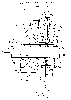
[0013] [FIG. 1] FIG. 1 is a longitudinal sectional front view of an essential
part of an
internal combustion engine equipped with a valve operating system related to
an
embodiment of the present invention. (first embodiment)
[FIG. 2] FIG. 2 is a sectional view along line 2-2 in FIG. 1. (first
embodiment)
4
CA 02771821 2012-02-22
[FIG. 3] FIG. 3 is an enlarged view of part 3 in FIG. 1. (first embodiment)
[FIG. 4] FIG. 4 is a view from arrow 4 in FIG. 2. (first embodiment)
[FIG. 5] FIG. 5 is a view from arrow 5 in FIG. 3. (first embodiment)
[FIG. 6] FIG. 6 is an exploded perspective view of an essential part of the
valve operating
system. (first embodiment)
[FIG. 7] FIG. 7 is a sectional view along line 7-7 in FIG. 3. (first
embodiment)
[FIG. 8] FIG. 8 is a sectional view along line 8-8 in FIG. 3. (first
embodiment)
[FIG. 9] FIG. 9 is a sectional view along line 9-9 in FIG. 3. (first
embodiment)
[FIG. 10] FIG. 10 is an operation diagram of the valve operating system
showing a state
of decompression release and exhaust gas recirculation suspension. (first
embodiment)
[FIG. 11] FIG. 11 is an operation diagram of the valve operating system
showing an
exhaust gas recirculation state. (first embodiment)
[FIG. 12] FIG. 12 is a graph showing an operational region of a decompression
cam
member and an exhaust gas recirculation cam member. (first embodiment)
[FIG. 13] FIG. 13 is a graph showing the relationship between crankshaft
rotational angle
and opening/closing timing of an intake valve and an exhaust valve. (first
embodiment)
EXPLANATION OF REFERENCE NUMERALS AND SYMBOLS
[0014] E Internal combustion engine
A Contracted position of first and second centrifugal weights
M Intermediate extension position of first and second centrifugal weights
B Extended position of second centrifugal weight
C Operating position of decompression cam member
D Non-operational position of decompression cam member
F Non-operational position of exhaust gas recirculation cam member
G Operating position of exhaust gas recirculation cam member
6 Crankshaft
17e Exhaust valve
20 Valve operating system
CA 02771821 2012-02-22
25 Valve operating cam
26 Camshaft
29i Intake valve operating member (intake rocker arm)
29e Exhaust valve operating member (exhaust rocker arm)
32 Driven rotating member (driven timing pulley)
351 First centrifugal weight
352 Second centrifugal weight
39 Recess
43 Return spring
46 Centrifugal mechanism
47 Decompression cam member
48 Exhaust gas recirculation cam member
BEST MODE FOR CARRYING OUT THE INVENTION
[0015] A mode for carrying out the present invention is explained below by
reference to a
preferred embodiment of the present invention shown in the drawings.
EMBODIMENT 1
[0016] In FIG. 1, an engine main body 1 of an internal combustion engine E is
formed
from a crankcase 2 in which a first case half 2a and a second case half 2b are
joined by a
bolt on inclined faces that obliquely intersect the axis of a crankshaft 6, a
cylinder block 3
extending upward from the second case half 2b, and a cylinder head 4
integrally molded
with an upper end part of the cylinder block 3. The crankcase 2 houses the
crankshaft 6,
which is supported by left and right side walls thereof, and the crankshaft 6
is connected via
a connecting rod 8 to a piston 7 fitted into a cylinder bore 3a of the
cylinder block 3. A
known recoil type starter 13 that can crank the crankshaft 6 is attached to
one side of the
engine main body 1.
In FIG. 1 and FIG. 2, formed in the cylinder head 4 are a combustion chamber
15
communicating with the cylinder bore 3a, and an intake port 16i and an exhaust
port 16e
having their inner ends opening in the combustion chamber 15, provided on the
cylinder
6
CA 02771821 2012-02-22
head 4 are an intake valve 17i and an exhaust valve 17e for opening and
closing the intake
port 16i and the exhaust port 16e, and mounted on the intake and exhaust
valves 17i and
17e are intake and exhaust valve springs 30i and 30e respectively for urging
the valves 17i
and 17e respectively in a valve-closing direction. A valve operating system 20
for driving
the intake valve 17i and the exhaust valve 17e for opening and closing in
cooperation with
the valve springs 30i and 30e is disposed from the crankcase 2 to the cylinder
head 4.
This valve operating system 20 is explained in detail later.
[0017] Screwed into the cylinder head 4 is a spark plug 21 having an electrode
facing the
combustion chamber 15, mounted on the cylinder head 4 are a carburetor 22 and
an exhaust
muffler 23 communicating with outer ends of the intake port 16i and the
exhaust port 16e
respectively, and attached to an air intake path inlet of the carburetor 22 is
an air cleaner 19.
[0018] Furthermore, mounted on an upper part of the crankcase 2 is a fuel tank
24
adjacent to the carburetor 22 and the exhaust muffler 23.
[0019] The valve operating system 20 is now explained.
[0020] As shown in FIG. 1 to FIG. 3, a valve operating chamber 20a is formed
that runs
from the cylinder block 3 to the cylinder head 4, the valve operating chamber
20a extending
upward from the interior of the crankcase 2 and being adjacent to one side of
the cylinder
bore 3a, and the valve operating system 20 is disposed in the valve operating
chamber 20a.
This valve operating system 20 includes a support shaft 27 disposed in
parallel to the
crankshaft 6 so as to traverse an upper part of the valve operating chamber
20a, and a
hollow cylindrical camshaft 26 rotatably supported on the support shaft 27.
The support
shaft 27 has its opposite ends fitted into a pair of support holes 28 and 28
of mutually
opposing side walls of the valve operating chamber 20a, and is fixed to the
cylinder head 4
by retaining an outer end part of the support shaft 27 with a retaining plate
52 secured to the
outside of the cylinder head 4 by a bolt 51.
[0021] As shown in FIG. 3 to FIG. 6, a single valve operating cam 25 is fitted
around and
secured to the outer periphery of one end part of the camshaft 26 by press-
fitting, etc. A
driven timing pulley 32 surrounding the other end part of the camshaft 26 is
integrally
7
CA 02771821 2012-02-22
molded at one end of the valve operating cam 25, and this driven timing pulley
32 is driven
via a timing belt 33 at a reduction ratio of 1/2 from a drive timing pulley 31
secured to the
crankshaft 6.
[0022] Mounted on the cylinder head 4 are an intake rocker shaft 34i and an
exhaust
rocker shaft 34e that are parallel to the camshaft 26 and are disposed on
opposite sides of
the intake and exhaust valves 17i and 17e, swingably supported on the intake
rocker shaft
34i is an intake rocker arm 29i providing a connection between the valve
operating cam 25
and the intake valve 17i, and swingably supported on the exhaust rocker shaft
34e is an
exhaust rocker arm 29e providing a connection between the valve operating cam
25 and the
exhaust valve 17e. These intake and exhaust rocker arms 29i and 29e have
mutually
different contact phases with the valve operating cam 25, receive a lifting
action from the
valve operating cam 25 at predetermined timings, and open and close the intake
and exhaust
valves 17i and 17e respectively in cooperation with the intake and exhaust
valve springs 30i
and 30e.
[0023] The valve operating system 20 is arranged as described above, and a
head cover
18 covering the valve operating system 20 from above is joined to an upper end
face of the
cylinder head 4.
[0024] As shown in FIG. 4 to FIG. 6, the driven timing pulley 32 is formed
from an arm
wall 32a spreading out in the radial direction from one end part of the valve
operating cam
25, and a toothed rim 32b formed on the outer periphery of the arm wall 32a,
one end part
of each of first and second centrifugal weights 351 and 352 formed in a
substantially U
shape so as to surround half of the periphery of the camshaft 26 being
swingably supported
by a single pivot shaft 36 fixedly provided on the arm wall 32a so as to
project on the
outside face thereof. The first and second centrifugal weights 351 and 352
have a plate
shape and are mutually superimposed, and an abutment piece 351a is formed at
the
swinging end of the first centrifugal weight 351 on the side opposite to the
pivot shaft 36,
the swinging end of the second centrifugal weight 352 being capable of
abutting against the
abutment piece 351a.
8
CA 02771821 2012-02-22
[0025] The first centrifugal weight 351 thus swings around the pivot shaft 36
from a
contracted position A (see FIG. 5) in which its U-shaped bent portion abuts
against an outer
peripheral face of a distance collar 49 on the camshaft 26 to an intermediate
extension
position M (see FIG. 10) in which the abutment piece 351a abuts against the
outer
peripheral face of the distance collar 49, and does not swing beyond the
intermediate
extension position M. Furtheimore, the second centrifugal weight 352 is
capable of
swinging around the pivot shaft 36 from a contracted position A to an extended
position B
via an intermediate operating position M; the contracted position A (see FIG.
5) for the
second centrifugal weight 352 is defined by the swinging end of the second
centrifugal
weight 352 abutting against the abutment piece 351a when the first centrifugal
weight 351
is in the contracted position A, the intermediate extension position M (see
FIG. 10) for the
second centrifugal weight 352 is defined by the swinging end of the second
centrifugal
weight 352 abutting against the abutment piece 351a when the first centrifugal
weight 351
is in the intermediate extension position M, and the extended position B (see
FIG. 11) for
the second centrifugal weight 352 is defined, when the first centrifugal
weight 351 is
restrained to the intermediate extension position M, by the second centrifugal
weight 352
being separated from the abutment piece 351a by a predetermined distance and
abutting
against a stopper piece 351b formed on a side edge of the first centrifugal
weight 351 on the
side opposite to the abutment piece 351a. A return spring 43 for urging the
second
centrifugal weight 352 toward the contracted position A side with a
predetermined set load
is provided in an extended state between a latching tab 40 of the second
centrifugal weight
352 and a latching pin 41 of the arm wall 32a. A centrifugal mechanism 46 for
operating
a drive ring 45, which is described later, is formed from the first
centrifugal weight 351, the
second centrifugal weight 352, and the return spring 43.
[0026] As shown in FIG. 3 and FIG. 7 to FIG. 9, the valve operating cam 25 is
provided
with a recess 39 surrounding the camshaft 26, the recess 39 opening on an
outside face of
the driven timing pulley 32 and on a base circle face 25a of the valve
operating cam 25, and
in this recess 39 an exhaust gas recirculation cam member 48, a decompression
cam
9
CA 02771821 2012-02-22
member 47, the drive ring 45, and the distance collar 49 are fitted onto the
camshaft 26 in
sequence from the valve operating cam 25 side. The exhaust gas recirculation
cam
member 48, the decompression cam member 47, and the drive ring 45 are
therefore all
housed in the recess 39 of the valve operating cam 25.
[0027] In FIG. 3 and FIG. 5 to FIG. 9, the drive ring 45 is rotatably fitted
onto an outer
peripheral face of the camshaft 26, a connecting projection 45a is integrally
formed with the
drive ring 45, the connecting projection 45a projecting from the outer
peripheral face
thereof and extending toward the first and second centrifugal weights 351 and
352 side, and
this connecting projection 45a engages with a connection groove 352a provided
on the
inner periphery of the swinging end part of the second centrifugal weight 352.
When the
second centrifugal weight 352 swings in the radial direction, the drive ring
45 is pivoted via
the connecting projection 45a. Furthermore, the drive ring 45 has in the axial
direction on
its inner peripheral face a retaining groove 45b, and a roller 44 is retained
by this retaining
groove 45b, the roller 44 extending in the axial direction of the camshaft 26
from the driven
timing pulley 32 to the valve operating cam 26e. This roller 44 can roll on
the outer
peripheral face of the camshaft 26 by rotation of the drive ring 45 relative
to the camshaft
26.
[0028] In FIG. 7 to FIG. 11, the decompression cam member 47 and the exhaust
gas
recirculation cam member 48 are fitted onto a pair of mutually parallel guide
faces 55 and
55, formed on opposite side faces of the camshaft 26, so that they can slide
along a
diameter of the camshaft 26. The decompression cam member 47 can thereby slide
between an operating position C (FIG. 8) and a non-operational position D
(FIG. 10) along
the guide faces 55 and 55, and the operating position C and the non-
operational position D
are defined by inner end faces 56a and 56b of the decompression cam member 47
abutting
against the outer peripheral face of the camshaft 26, the inner end faces 56a
and 56b being
in a direction perpendicular to the guide faces 55 and 55. Furthermore, the
exhaust gas
recirculation cam member 48 can slide between a non-operational position F
(FIG. 7) and
an operating position G (FIG. 11) along the guide faces 55 and 55, and the
operating
CA 02771821 2012-02-22
position F and the non-operational position G are defined by inner end faces
57a and 57b of
the exhaust gas recirculation cam member 48 abutting against the outer
peripheral face of
the camshaft 26, the inner end faces 57a and 57b being in a direction
perpendicular to the
guide faces 55 and 55.
[0029] The decompression cam member 47 and the exhaust gas recirculation cam
member 48 integrally have on their outer peripheral faces convex cams 47a and
48a that are
much lower than a nose portion of the valve operating cam 25, and these convex
cams 47a
and 48a project outside the base circle face 25a of the valve operating cam 25
at the
operating positions C and G and are withdrawn inside the base circle face 25a
at the non-
operational positions D and F. Moreover, the convex cam 47a of the
decompression cam
member 47 is disposed so as to push up the exhaust rocker arm 29e during a
compression
stroke of the engine when the decompression cam member 47 occupies the
operating
position C, and the convex cam 48a of the exhaust gas recirculation cam member
48 is
disposed so as to push up the exhaust rocker arm 29e during intake stroke of
the engine
when the exhaust gas recirculation cam member 48 occupies the operating
position G.
[0030] As shown in FIG. 8, a concave cam 58 is formed in a central part of the
inner end
face 56b, on the convex cam 47a side, of the decompression cam member 47, the
concave
cam 58 operating in cooperation with the roller 44. This concave cam 58 is
formed from
an inclined face 58a that forces the decompression cam member 47 to the
operating position
C by being pressed by the roller 44 when the second centrifugal weight 352 is
retained at
the contracted position A by the urging force of the return spring 43, and an
arc-shaped
bottom face 58b that allows the decompression cam member 47 to move to the non-
operational position D by avoiding interference with the roller 44 when the
second
centrifugal weight 352 swings to the intermediate extension position M. The
decompression cam member 47 has its center of gravity offset from the center
of the
decompression cam member 47 toward the side opposite to the concave cam 58,
and when
the roller 44 attains a position facing the arc-shaped bottom face 58b the
decompression
cam member 47 moves to the non-operational position D by centrifugal force
acting on the
11
CA 02771821 2012-02-22
center of gravity.
[0031] On the other hand, as shown in FIG. 7 and FIG. 11, a concave cam 59 is
formed in
a central part of the inner end face 57b, on the convex cam 48a side, of the
exhaust gas
recirculation cam member 48, the concave cam 59 operating in cooperation with
the roller
44. This concave cam 59 is formed from an arc-shaped bottom face 59a that
allows the
exhaust gas recirculation cam member 48 to move to the non-operational
position F by
avoiding interference with the roller 44 while the second centrifugal weight
352 rotates
from the contracted position A to the intermediate extension position M, and
an inclined
face 59b that forces the exhaust gas recirculation cam member 48 to the
operating position
G by being pressed by the roller 44 when the second centrifugal weight 352
swings to the
extended position B. The exhaust gas recirculation cam member 48 has its
center of
gravity offset from the center of the exhaust gas recirculation cam member 48
toward the
side opposite to the concave cam 59, and when the roller 44 is at a position
facing the arc-
shaped bottom face 59a the exhaust gas recirculation cam member 48 moves to
the non-
operational position G by centrifugal force acting on the center of gravity.
[0032] The operation of this embodiment is now explained.
[0033] When the crankshaft 6 rotates, since the drive timing pulley 31 drives
the driven
timing pulley 32 via the timing belt 33, the valve operating cam 25, which is
integral with
the driven timing pulley 32, is also driven to rotate. During the intake
stroke, the nose
portion of the valve operating cam 25 swings the intake rocker arm 29i to thus
push and
open the intake valve 17i against the urging force of the intake valve spring
30i.
Similarly, during the exhaust stroke, the nose portion of the valve operating
cam 25 swings
the exhaust rocker arm 29e so as to push and open the exhaust valve 17e. The
opening/closing timings of the intake valve 17i and the exhaust valve 17e are
shown in FIG.
13.
[0034] In FIG. 12, in an engine starting rotational region a in which the
engine rotational
speed Ne is between 0 and a predetermined rotational speed Ne 1 that is lower
than the
idling rotational speed, as shown in FIG. 4, FIG. 5, and FIG. 8, the first and
second
12
CA 02771821 2012-02-22
centrifugal weights 351 and 352 are together retained at the contracted
position A by the set
load of the return spring 43. In this process, the drive ring 45 connected to
the second
centrifugal weight 352 via the connecting projection 45a presses the roller 44
against the
inclined face 58a of the concave cam 58 of the decompression cam member 47,
and the
decompression cam member 47 is therefore retained at the operating position C
in which
the convex cam 47a of the decompression cam member 47 projects further outward
than the
base circle face 25a of the valve operating cam 25.
[0035] If the recoil type starter 13 is now operated in order to start the
internal
combustion engine E, since the crankshaft 6 is cranked by the starter 13 via a
starting
tubular shaft 12 and at the same time the valve operating cam 25 is driven to
rotate via the
timing belt 33, etc., the convex cam 47a of the decompression cam member 47
pushes up
the exhaust rocker arm 29e slightly during the compression stroke of the
piston 7 as
described above, and the exhaust valve 17e is opened slightly. The timing in
this process
is shown in FIG. 10. As a result, part of the compressed gas within the
cylinder bore 3a is
discharged to the exhaust port 16e to thus suppress the increase in
compression pressure,
the operating load on the starter 13 is therefore decreased, the crankshaft 6
can be cranked
relatively lightly and swiftly, and the engine can thus be easily started.
[0036] When the engine is started and the engine rotational speed Ne increases
beyond
the starting rotational region a, as shown in FIG. 10 the moment around the
pivot shaft 36
due to the total centrifugal force of the first and second centrifugal weights
351 and 352
counteracts the moment around the pivot shaft 36 of the first centrifugal
weight 351 due to
the set load of the return spring 43, the first and second centrifugal weights
351 and 352
swing outward as a unit in the radial direction from the contracted position
A, the abutment
piece 351a of the first centrifugal weight 351 abuts against the outer
peripheral face of the
distance collar 49 on the camshaft 26, both the first and second centrifugal
weights 351 and
352 attain the intermediate extension position M, and only the first
centrifugal weight 351
is prevented from extending therebeyond. Swinging of the second centrifugal
weight 352
from the contracted position A to the intermediate extension position M during
this process
1)
CA 02771821 2012-02-22
is transmitted to the connecting projection 45a so as to rotate the drive ring
45 in the
anticlockwise direction in FIG. 10, and the roller 44 is moved to a position
facing the
bottom face 58b of the concave cam 58 of the decompression cam member 47.
Therefore,
the decompression cam member 47 is moved to the non-operational position D by
the
action of centrifugal force without interference from the roller 44, and the
convex cam 47a
is withdrawn inside the base circle face 25a of the valve operating cam 25.
[0037] In this process, in the exhaust gas recirculation cam member 48, as
shown in FIG.
7, since the bottom face 59a of the concave cam 59 faces the roller 44 of the
drive ring 45,
the exhaust gas recirculation cam member 48 is also retained at the non-
operational position
F by centrifugal force without being restrained by the roller 44, and the
convex cam 48a is
withdrawn inside the base circle face 25a of the valve operating cam 25.
[0038] As hereinbefore described, the exhaust valve 17e is controlled so as to
open and
close as usual depending only on the original shape of the valve operating cam
25.
[0039] Since, when the first centrifugal weight 351 attains the intermediate
extension
position M, swinging to extend therebeyond is prevented by the camshaft 26,
after the
engine rotational speed Ne has increased to Nel or above the load acting on
the return
spring 43 is constant while the second centrifugal weight 352 does not depart
from the
abutment piece 351a of the first centrifugal weight 351. Therefore, in the
engine
rotational speed region Ne 1 to Ne2, where the return spring 43 cannot be
deformed by the
centrifugal force of the second centrifugal weight 352 alone, that is, the low-
speed running
region b including idling, the second centrifugal weight 352 is retained at
the intermediate
extension position M.
[0040] When the engine rotational speed Ne attains Ne2 or above, that is, it
enters the
high-speed running region c, the centrifugal force of the second centrifugal
weight 352
increases sufficiently, the moment around the pivot shaft 36 of the second
centrifugal
weight 352 due to the centrifugal force thereof becomes larger than the moment
of the
second centrifugal weight 352 due to the load of the return spring 43, as
shown in FIG. 11
the second centrifugal weight 352 attains the extended position B, and the
accompanying
14
CA 02771821 2012-02-22
rotation of the drive ring 45 in the anticlockwise direction makes the roller
44 press the
inclined face 59b of the concave cam 59 of the exhaust gas recirculation cam
member 48 to
thus make the exhaust gas recirculation cam member 48 move to the operating
position G
against the centrifugal force, and the exhaust gas recirculation cam member 48
makes the
convex cam 48a project from the base circle face 25a of the valve operating
cam 25.
Therefore, as described above, during the intake stroke of the piston 7 the
convex cam 48a
of the exhaust gas recirculation cam member 48 pushes up the exhaust rocker
arm 29e
slightly, thereby opening the exhaust valve 17e slightly. As a result, exhaust
gas
remaining in the exhaust port 16e is sucked into the combustion chamber 15,
that is,
exhaust gas recirculation is carried out. This exhaust gas suppresses
excessive increase in
combustion temperature when a gas mixture is burned in the expansion stroke at
a later
stage, thus contributing to reduction of the NOx concentration in the exhaust
gas and
reduction in HC concentration, and consequently improving the fuel economy.
[0041] As hereinbefore described, the centrifugal mechanism 46 formed from the
first
and second centrifugal weights 351 and 352 and the return spring 43 operates
the common
drive ring 45 and operates the decompression cam member 47 and the exhaust gas
recirculation cam member 48 in sequence, thereby simplifying the structure of
the valve
operating system 20, which has a decompression function and an exhaust gas
recirculation
function with desired characteristics without mutual interference, and making
it compact.
[0042] Moreover, since the centrifugal mechanism 46 is mounted on the outside
face of
the driven timing pulley 32, and the decompression cam member 47 and the
exhaust gas
recirculation cam member 48 are housed in the recess 39 of the valve operating
cam 25,
which is integrally formed with the driven timing pulley 32, and are supported
by the
camshaft 26, it is possible to house the decompression cam member 47 and the
exhaust gas
recirculation cam member 48 within the valve operating cam 25, thereby making
the valve
operating system 20 yet more compact.
[0043] Furthermore, in the centrifugal mechanism 46, setting the contracted
position A
and the intermediate extension position M for the first and second centrifugal
weights 351
CA 02771821 2014-01-16
and 352 and setting the extended position B for the second centrifugal weight
352 enables
the operational timing for the decompression cam member 47 and the exhaust gas
recirculation cam member 48 to be achieved easily and reliably.
[0044] Moreover, the intake rocker arm 29i and the exhaust rocker arm 29e for
opening
and closing the intake valve 17i and the exhaust valve 17e respectively are in
sliding
contact with the outer peripheral face of the valve operating cam 25 with
mutually
displaced phases, and it is thereby possible to open and close the intake and
exhaust valves
17i and 17e by the single common valve operating cam 25, thus making the valve
operating
system 20 even more compact.
[0045] The present invention is not limited to the above-mentioned embodiment
and may
be modified in a variety of ways. For example, the valve operating cam 25 and
the camshaft
26 may be molded integrally as a single component. The stopper piece 351b for
restricting
the extended position B of the second centrifugal weight 352 may be
eliminated, and the
extended position B for the second centrifugal weight 352 may be restricted by
the roller 44
abutting against a side end wall of the bottom face 58B of the concave cam 58
of the
decompression cam member 47.
[0046] Furthermore, when the present invention is applied to a valve operating
system in
which an intake cam and an exhaust cam are provided on a camshaft 26, a
decompression
cam member 47 and an exhaust gas recirculation cam member 48 may be housed in
a cam
that is close to a driven timing pulley 32. Furtheiniore, a timing
transmission system
formed from a drive timing pulley 31, a driven timing pulley 32, and a timing
belt 33 may
be of a gear type. In this case, the driven timing rotating member of the
present invention
is formed from a driven timing gear.
16