Note: Descriptions are shown in the official language in which they were submitted.
CA 02772412 2016-09-16
- 1 -
A METHOD OF UNDERGROUND ROCK BLASTING
TECHNICAL FIELD
The invention relates to the field of mining, including the blasting and
fragmentation of rock. More specifically, the invention relates to the
blasting of rock at a
location underground.
BACKGROUND
In mining operations, the efficient fragmentation and breaking of rock by
means of
explosive charges demands considerable skill and expertise. The explosive
charges are
placed in appropriate quantities at predetermined positions within the rock
and are then
actuated via detonators having predetermined time delays, thereby providing a
desired
pattern of blasting and rock fragmentation. Traditionally, signals are
transmitted to the
detonators from an associated blasting machine via non-electric systems
employing low
energy detonating cord (LEDC) or shock tube. Alternatively, electrical wires
may be used
to transmit firing signals to electrical detonators or more sophisticated
signals to and from
electronic detonators. For example, such signalling may include ARM, DISARM,
and
delay time instructions for remote programming of the detonator firing
sequence.
Moreover, as a security feature, detonators may store firing codes and respond
to ARM
and FIRE signals only upon receipt of matching firing codes from the blasting
machine.
Electronic detonators can be programmed with time delays with an accuracy down
to 1 ms
or less.
The establishment of a wired blasting arrangement involves the correct
positioning
of explosive charges within boreholes in the rock, and the proper connection
of wires
between an associated blasting machine and the detonators. The process is
often labour
intensive and highly dependent upon the accuracy and conscientiousness of the
blast
operator. Importantly, the blast operator must ensure that the detonators are
in proper
signal transmission relationship with a blasting machine, in such a manner
that the blasting
machine at least can transmit command signals to control each detonator, and
in turn
actuate each explosive charge. Inadequate connections between components of
the
blasting arrangement can lead to loss of communication between blasting
machines and
CA 02772412 2012-02-28
WO 2011/038449 PCT/AU2010/001273
- 2 -
detonators, and therefore increased safety concerns. Significant care is
required to ensure
that the wires run between the detonators and an associated blasting machine
without
disruption, snagging, damage or other interference that could prevent proper
control and
operation of the detonator via the attached blasting machine.
Wireless detonator systems offer the potential for circumventing these
problems,
thereby improving safety at the blast site. By avoiding the use of physical
connections
(e.g. electrical wires, shock tubes, LEDC, or optical cables) between
detonators and other
components at the blast site (e.g. blasting machines) the possibility of
improper set-up of
the blasting arrangement is reduced. Another advantage of wireless detonators
relates to
facilitation of automated establishment of the explosive charges and
associated detonators
at the blast site. This may include, for example, automated detonator loading
in boreholes
and automated association of a corresponding detonator with each explosive
charge, for
example involving robotic systems. This would provide dramatic improvements in
blast
site safety since blast operators would be able to set up the blasting array
from entirely
remote locations. However, such systems present formidable technological
challenges,
many of which remain unresolved. One obstacle to automation is the difficulty
of robotic
manipulation and handling of detonators at the blast site, particularly where
the detonators
are not wireless electronic detonators and require tieing-in or other forms of
hook up to
electrical wires, shock tubes or the like.
Underground mining presents distinct challenges compared to surface mining.
For
example, the fragmentation and extraction of a body of ore located underground
requires
careful planning and execution. Typically, the body of ore is accessed via
tunnelling, or
one or more drives, to expose a face of the ore on at least one side.
Boreholes are then
drilled into the face, and loaded with explosive charges. Actuation of the
charges by
means of associated detonators fragments a portion of the rock behind the free
face,
thereby to expose a new face to be drilled and loaded. Meanwhile, fragmented
rock from
the initial blast can be removed via the access tunnel for processing. Through
repeated
cycles of drilling, loading, blasting and extraction, the exposed face
retreats into the ore
body and fragmented ore is retrieved.
Extraction of the fragmented ore may be performed using driven vehicles or
remotely controlled vehicles, but as noted above remotely controlled location
of the
CA 02772412 2012-02-28
WO 2011/038449 PCT/AU2010/001273
- 3 -
detonators in the boreholes and their operative association with the explosive
charges has
yet to be developed.
Whilst simple in nature, underground blasting as described above presents
significant technical and organizational challenges. For example, on the
technical side, the
void created must be structurally sound, and may require internal support to
prevent ceiling
collapse. To this end, columns or pillars of ore are frequently left in place
to assist in
providing ceiling support, particularly during the active phase of blasting
and extraction of
the remaining ore. Thus, portions of the valuable ore body are effectively
"left behind" at
the underground blast site, at least until the void has been structurally
reinforced, reducing
the efficiency of the ore extraction process.
The complexity of underground mining operations is further exacerbated by
organizational challenges at the mine site. Teams of mine workers must be co-
ordinated
carefully in order to optimize both mining operations and access to the free
face and
fragmented rock. For example, different teams may be required to access the
free face at
different times to drill boreholes, load explosives, set up blasting
equipment, extract
fragmented rock etc. Each team will need a different set of equipment to
effectively
perform its designated task, and yet there may be insufficient space at the
free face to
accommodate more than one team, and associated equipment, at any given time.
Furthermore, fragmented material from one blast, or a void resulting from that
blast, may prevent access to the ore body on a remote side of that blast,
again meaning that
portions of the valuable ore body are effectively "left behind", at least
until the fragmented
material has been extracted or access has been otherwise facilitated.
Moreover, team
movement and co-ordination at the mine site is further complicated by safety
concerns.
Depending upon the integrity of the rock, or the safety rules at the mine
site, it may be a
requirement to completely evacuate the mine site of all mining personnel (and
perhaps
equipment) when blasting takes place. Alternatively, or in addition, it may be
necessary to
reinforce the remaining rock mass before personnel are allowed to access it
for further
drilling and blasting. Without such reinforcement, that remaining rock mass
may also have
to be "left behind". All of these possibilities further constrain the
scheduling of all other
operations at the mine site for all working faces.
CA 02772412 2016-09-16
- 4 -
In addition, it may be difficult to access the retreating face of the ore
body. Each
blasting cycle requires the substantial removal of fragmented rock before the
newly
exposed ore face can be drilled and loaded for the next blasting cycle. If the
rock
fragmentation is inefficient or inappropriate in some way, it may be difficult
to fully
extract the ore via the access tunnel, and this in turn may delay the
extraction process. On
occasion, undesirable rock fragmentation or throw may result in the ore body
being
completely inaccessible from an existing access tunnel, such that a new tunnel
must be
formed to approach the ore body from a different angle. Clearly, this will
delay the
extraction process, and increase the costs significantly.
It follows that there is a continuing need in the art for improved blasting
methods
for underground mining. This need extends to blasting arrangements that employ
either
wired or wireless communication with detonators and associated components.
SUMMARY
It is an object to provide methods for improved blasting of rock at an
underground
location.
In selected exemplary embodiments there is provided a method of blasting rock
at
an underground blast site, the method comprising the steps of:
a) drilling boreholes in a rock mass;
b) loading each borehole with at least one charge of explosive material;
c) placing at least one detonator in operative association with each
charge;
d) conducting a sequence of at least two initiation events to blast the
rock
mass, in each of which only some of the charges are initiated, by sending
firing
signals to only the detonators associated with said charges and in which each
initiation event is a discrete user-controlled initiation event;
wherein one of the at least two initiation events creates a stranded portion
of
the rock mass that has been drilled and charged in steps a), b) and c) and
said
stranded portion of the rock mass is blasted in a subsequent one or more of
the at
least two initiation events without personnel accessing said stranded portion.
By this method, the efficiency and safety of blasting underground can be
greatly
enhanced. By pre-drilling all of a selected rock mass or body of ore, or a
selected portion
CA 02772412 2016-09-16
- 5 -
of the mass or body, and then charging all of the drilled boreholes as desired
and placing
the detonators in operative association with the explosive charges, all of the
charges may
be initiated by at least two distinct initiation events in a desired sequence
without
personnel having to access any portion of the mass or body between initiation
events. This
means that a stranded portion of the rock mass can be readily and safely
blasted and the
fragmented material recovered.
Select methods allow entirely new sequences of blasting to be achieved. In
particular, it is no longer necessary to perform retreat mining ¨ that is,
blasting at the
furthest point of the rock mass from an access point ¨ or to drill and blast
individual levels
at a time. It is now possible to perform steps a), b) and c) to the full
height of the rock
mass, or selected portion of the rock mass, and, if desired, selectively blast
different levels
of the rock mass in respective initiation events. The rock mass or selected
portion of the
rock mass may be between two drives or tunnels, one above the other.
Generally, the boreholes will be drilled in the rock mass from a top drive or
a
bottom drive, which bottom drive may be the only drive, and in one embodiment
the
boreholes are drilled in step a) from along the entire length of the drive.
Thus, the length
of the drive defines the extent of the rock mass that is to be blasted in the
at least two
initiation events.
Select methods require accurate initiation of the detonators, and in
embodiments
the detonators may be electric or electronic detonators. In a particular
embodiment, the
detonators are electronic. Such electronic detonators may be wired or
wireless. However,
there is a risk that wiring connecting, for example, a blasting mechanism to
the detonators
that are initiated in a subsequent one of the at least two initiation events
may be damaged
by the earlier initiation, and for this reason wireless detonators are likely
to be selected.
In an embodiment, each detonator forms part of a wireless detonator assembly
for
receiving and responding to wireless command signals, the step of conducting a
sequence
of at least two initiation events comprising transmitting at least two
wireless command
signals from one or more associated blasting machines to selectively FIRE the
wireless
detonator assemblies.
CA 02772412 2012-02-28
WO 2011/038449 PCT/AU2010/001273
- 6 -
In a particular embodiment, each wireless detonator assembly is a wireless
electronic booster.
In some embodiments, the detonators associated with the subsequent one or more
of the at least two initiation events enter a sleep mode prior to their
actuation.
Since the charges of explosive material for the subsequent one or more
initiation
events must be in place during the earlier of the at least two initiation
events, the explosive
material must be relatively stable, for example ANFO or a bulk emulsion
explosive. A
suitable bulk emulsion explosive may be selected from the FortisTM range from
Orica
Mining Services.
The effect of each initiation event is to fragment the blasted portion of the
rock
mass, which may then fall into a bottom drive. It may be necessary to extract
all or some
of that fragmented rock prior to a subsequent one of the at least two
initiation events. This
may be done remotely, or safely from a portion of the bottom drive that has
been drilled
and loaded, and that has had at least one detonator placed in operative
association with
each charge, but that is not unsupported ground so remains stable ¨ that is,
it is not a
stranded portion of the rock mass.
Such a stranded portion of the rock mass may be a pillar of rock that is left
in place
after one of the at least two initiation events to support other portions of
the rock mass.
In one particular embodiment, the rock mass comprises a body of ore above a
bottom drive and the boreholes are drilled in an upwards direction from the
bottom drive
into the body, the method further comprising forming at least one rise in the
ore extending
in a generally upward direction from the bottom drive, optionally by actuating
detonators
and associated charges in at least one borehole, whereby in said one of the at
least two
initiation events material from the body of ore adjacent the rise is
fragmented and falls into
the rise and the bottom drive for extraction via the bottom drive, leaving a
void, perhaps
with unsupported ground, and whereby in a subsequent one or more of the at
least two
initiation events, remaining material of the body of ore is fragmented and
falls at least
partly into the void.
In this embodiment, in the subsequent one or more of the at least two
initiation
events portions of the body of ore adjacent the void and upper ends of the
boreholes may
CA 02772412 2012-02-28
WO 2011/038449 PCT/AU2010/001273
- 7 -
be fragmented, and optionally extracted via the bottom drive, prior to the
last of the body
of ore between said portions and the bottom drive being fragmented.
In one version of this embodiment, said material of the body of ore fragmented
in
the one of the at least two initiation events is to one side of the rise, in
the longitudinal
direction of the bottom drive, and said material of the body of ore fragmented
in a
subsequent one or more initiation events is to the opposite side of the rise.
The portion of the body of ore fragmented in a subsequent one or more
initiation
events may be above the portion of the body of ore fragmented in the one of
the at least
two initiation events.
The initiation events may be repeated along the bottom drive. The bottom drive
may have one or two blind ends.
In this one particular embodiment, there may be no drive above the bottom
drive.
In another particular embodiment, the rock mass comprises a body of ore
extending
between a bottom drive and an upper drive, said bottom and upper drives each
having a
corresponding blind end, and the boreholes are drilled in a downwards
direction from the
upper drive into the body, the method further comprising forming at least one
rise in the
ore extending between the upper and bottom drives and remote from said blind
end of the
drives, optionally by actuating detonators and associated charges in at least
one borehole,
said one of the at least two initiation events being adjacent the rise and
leaving a void,
perhaps with unsupported ground, and a subsequent one or more of the
initiation events
being performed in one or more portions of the body of ore between the rise
and the blind
end of the drives to fragment the material of said one or more portions such
that the
fragmented material can be extracted via the bottom drive..
In yet another particular embodiment, the rock mass comprises a body of ore
extending between a bottom drive and an upper drive adjacent a stope formed
between the
bottom and upper drives at a remote end thereof and the boreholes are drilled
in the body
of ore from one of the drives towards the other drive, the method further
comprising
forming at least one rise in the ore between the bottom and upper drives and
remote from
said stope to form a portion of the body of ore between the stope and the
rise, said one of
the at least two initiation events being in the body of ore adjacent said rise
to leave a pillar
formed from said portion of the body of ore and a subsequent one or more of
the at least
CA 02772412 2012-02-28
WO 2011/038449 PCT/AU2010/001273
- 8 -
two initiation events being performed in the residual body of ore to the side
of the location
of the rise remote from the pillar, followed by extraction of fragmented
material from the
bottom drive, and a further subsequent one or more of the at least two
initiation events
being performed to fragment the material of the pillar.
In this embodiment, the stope may be at least partially filled with backfill
material,
which may be introduced from the upper drive to replace the fragmented and
extracted
material of the body of ore.
Each of said another particular embodiment and said yet another particular
embodiment may be performed using features of said one particular embodiment.
The boreholes in these embodiments may be drilled in any known manner, for
example at from 0 to 450 to vertical. In one embodiment, at least some of the
boreholes are
arranged in a ring of boreholes centred on the drive from which they are
drilled for ring-
firing of some of the detonators in accordance with pre-programmed delay
times.
BRIEF DESCRIPTION OF THE DRAWINGS
Embodiments of methods of blasting according to the invention, and a prior art
method, will now be described, with reference to the accompanying drawings, in
which:
Figure 1 a provides a schematic perspective view of body of ore, that may be
blasted
according to the invention;
Figure lb provides a schematic sectional view of the body of ore illustrated
in Figure 1 a
taken along the boreholes;
Figure 2a-h illustrate sequential stages in the blasting and extraction of a
body of ore
located underground, in accordance with methods that are known in the art;
Figure 3a-h illustrate sequential stages in the blasting and extraction of a
body of ore
located underground in accordance with an embodiment of the method of the
invention;
Figure 4 is a schematic perspective view of the first stage of one embodiment
of a drawbell
blast in accordance with the invention;
Figure 5 is a view similar to Figure 4, but showing the second stage of the
blast;
Figure 6 is a schematic perspective view the first stage of another embodiment
of a
drawbell blast in accordance with the invention;
Figure 7 is a view similar to Figure 6, but showing the second stage of the
blast;
CA 02772412 2012-02-28
WO 2011/038449 PCT/AU2010/001273
- 9 -
Figure 8 is a schematic perspective view of a first stage of yet another
embodiment of a
method of blasting in accordance with the invention, retreat blasting and
backfilling of the
resultant stope;
Figure 9 is a view similar to Figure 8, but showing the second stage of the
blast;
Figure 10 is a view similar to Figure 8, but showing the third stage of the
blast;
Figure 11 is a view similar to Figure 8, but showing the fourth stage of the
blast;
Figure 12 is a view similar to Figure 8, but showing the fifth stage of the
blast; and
Figure 13 is a view similar to Figure 8, but showing the sixth stage of the
blast.
DEFINITIONS:
Actuate or initiate: refers to the initiation, ignition, or triggering of
explosive materials,
typically by way of a primer, detonator or other device, such as a booster,
capable of
receiving an external signal and converting the signal to cause deflagration
of the explosive
material.
Array: refers to a group of discrete explosive charges, preferably emulsion
explosive
charges, each located in adjacent borehole in operable association with a
detonator such
that the charges are located generally within a layer or section of rock,
whereby actuation
of the charges causes blasting and fragmentation of the layer or section of
rock. In selected
embodiments, the group of charges forms an array that is substantially
arranged about a
plane generally perpendicular to a general direction of the axes of the
boreholes. In further
selected embodiments, the groups of charges that forms an array may be
arranged in a
manner other than planar. Numerous array configurations and arrangements are
known in
the art including but not limited to rings, fans, and cuts of various kinds.
Base charge: refers to any discrete portion of explosive material in the
proximity of other
components of a detonator and associated with those components in a manner
that allows
the explosive material to actuate upon receipt of appropriate signals from the
other
components. The base charge may be retained within the main casing of a
detonator, or
alternatively may be located nearby the main casing of a detonator. The base
charge may
be used to deliver output power to an external explosives charge to initiate
the external
explosives charge.
CA 02772412 2012-02-28
WO 2011/038449 PCT/AU2010/001273
- 10 -
Blasting machine: refers to any device that is capable of being in signal
communication
with a detonator to actuate the detonator. In the case of electronic
detonators, the signal
communication may be, for example, to send ARM, DISARM, and FIRE signals to
the
detonators, and / or to program the detonators with delay times and / or
firing codes. The
blasting machine may also be capable of receiving information such as delay
times or
firing codes from the detonators directly, or this may be achieved via an
intermediate
device such as a logger to collect detonator information and transfer the
information to the
blasting machine.
Booster: refers to any device that can receive command signals from an
associated
blasting machine, and in response to appropriate signals such as a signal to
FIRE, can
cause actuation of a discrete explosive charge that forms an integral
component of the
booster. In this way, the actuation of the discrete explosive charge may
induce actuation of
an external quantity of explosive material, such as material charged down a
borehole in
rock. The booster may be wired or wireless. In selected embodiments, a booster
may
comprise the following non-limiting list of components: a detonator comprising
a firing
circuit and a base charge; an explosive charge in operative association with
said detonator,
such that actuation of said base charge via said firing circuit causes
actuation of said
explosive charge; a transceiver for receiving and processing at least one
wireless command
signal from a blasting machine, the transceiver being in signal communication
with said
firing circuit such that upon receipt of a command signal to FIRE said firing
circuit causes
actuation of said base charge and thereby actuation of said explosive charge.
Detonator: refers to any form of detonator, but in advantageous embodiments to
an
electronic or electric detonator, and many forms of detonators are known in
the art. As a
minimum, a detonator comprises a base charge to be initiated upon receipt of
an
appropriate signal, and means such as a firing circuit to convey an
appropriate signal to
actuate the base charge. Typically, many detonators will also comprise some
form of shell
to contain one or more components of the detonator. Traditionally, a shell is
composed of
a substantially tubular section of material (e.g. metal) to define a
percussion actuation end
of the detonator, at which the base charge resides, and an opposite end for
connection to
other components or signal transmission lines. In selected embodiments,
'detonator'
relates to those detonators that include programmable initiation means, for
example that
CA 02772412 2012-02-28
WO 2011/038449 PCT/AU2010/001273
- 11 -
include means to store unique detonator identification information, and / or
detonator firing
codes. The detonator may be wired or wireless. Electronic detonators are known
in the art
and may include memory means to store data such as delays times, firing codes,
or security
information, and/or be connected to top-boxes or other components of a
wireless initiation
device.
Distal: refers to an end of a borehole opposite a proximal end (wherein a
proximal end is
at, adjacent, or near a free face of rock from which the borehole was drilled
into the rock,
or from which fragmented rock was removed following blasting of rock at a free
face).
Such a free face may form part of a drive. The distal end may be a closed end
of the
borehole some distance away from a free face of rock, for example produced by
the
penetration into the rock of a drilling device such as a drill bit. In
alternative
embodiments, the distal end of a borehole may also be an open end if the
distal end
extends into another drive in the rock remote from the free face.
Drive: refers to a horizontal or generally horizontal cut or void extending
underground
through, above or below a body of ore. Typically, a drive is formed by
fragmentation and
extraction of rock, for example by tunnelling. The drive may provide access
for mine
operators and their equipment to drill boreholes extending into the body or
ore in any
direction for loading with explosive materials, blasting and fragmentation of
the body of
ore, for extraction via the drive and drive access. Any underground mine site
may include
one, a few, or many drives for example at different levels relative to the
surface of the
ground, or the body of ore. A drive is sometimes referred to herein as a
tunnel.
Explosive charge / charge: generally refers to a specific portion of an
explosive material in
or for placing into a borehole. An explosive charge is typically of a form and
sufficient
size to receive energy derived from the actuation of a base charge or a
detonator, or
alternatively energy from explosive material forming part of a booster. The
ignition of the
explosive charge should be sufficient to cause blasting and fragmentation of
the rock. The
chemical constitution of the explosive charge may take any form that is known
in the art.
In some embodiments the explosive charge is of a bulk emulsion explosive that
has good
stability such as those provided under the FortisTM brand by Orica Mining
Services.
Layer: refers to any layer of rock, in any orientation relative to horizontal,
that contains an
array of explosive charges associated in use with detonators. The layer may
include an
CA 02772412 2012-02-28
WO 2011/038449 PCT/AU2010/001273
- 12 -
array that is arranged in a substantially planar manner in the layer, or an
array that is less
organized in terms of its geometry. In this way, the detonators associated
with the
explosive charges may be controlled and actuated within the layer as a group,
thereby to
selectively fragment the layer as desired in accordance with a designed blast.
Proximal: refers to an end of a borehole at, adjacent, or near a free face of
rock from
which the borehole was drilled into the rock, or, in some embodiments, from
which
fragmented rock was removed following blasting of rock at a free face.
Rock: includes all types of rock, including valuable ore. Such valuable ore
includes shale.
Stranded portion of the rock mass: refers to any portion of the rock mass or
ore that is "left
behind", or which will be "left behind", at an underground location during a
blasting
process because it is physically inaccessible as a result of the one and/or an
earlier one of
the at least two initiation events and/or because it is unsupported ground
that is potentially
dangerous for personnel to access (so that personnel access may be prohibited
under
relevant regulation(s)) and/or because it may be required to remain at the
blast site to
maintain the structural integrity of the blast site, including any void
created by extraction
of rock ore at the blast site. The stranded portion of the rock mass comprises
ore that has
value and that in accordance with the invention is blasted in a subsequent one
or more of
the at least two initiation events without persormel accessing the stranded
portion.
Wireless: refers to there being no physical wires (such as electrical wires,
shock tubes,
LEDC, or optical cables) connecting the detonator of the invention or
components thereof
to an associated blasting machine or power source. The wireless energy may
take any
form appropriate for wireless communication and / or wireless charging of the
detonators.
For example, such forms of energy may include, but are not limited to,
electromagnetic
energy including light, infrared, radio waves (including ULF), and microwaves,
or
alternatively make take some other form such as electromagnetic induction or
acoustic
energy.
Wireless detonator assembly: in general the expression "wireless detonator
assembly"
encompasses a detonator, most preferably an electronic detonator (typically
comprising at
least a detonator shell and a base charge) as well as means to cause actuation
of the base
charge upon receipt by said wireless detonator assembly of a signal to FIRE
from at least
one associated blasting machine. For example, such means to cause actuation
may include
CA 02772412 2012-02-28
WO 2011/038449 PCT/AU2010/001273
- 13 -
signal receiving means, signal processing means, and a firing circuit to be
activated in the
event of a receipt of a FIRE signal. Preferred components of the wireless
detonator
assembly may further include means to transmit information regarding the
assembly to
other assemblies or to a blasting machine, or means to relay wireless signals
to other
components of the blasting apparatus. Other preferred components of a wireless
detonator
assembly will become apparent from the specification as a whole. The
expression
"wireless detonator assembly" may in very specific embodiments pertain simply
to a
wireless signal relay device, without any association to a detonator unit. In
such
embodiments, such relay devices may form wireless trunk lines for simply
relaying
wireless signals to and from blasting machines, whereas other wireless
detonator
assemblies in communication with the relay devices may comprise all the usual
features of
a wireless detonator assembly, including a detonator for actuation thereof, in
effect
forming wireless branch lines in the wireless network. A wireless detonator
assembly may
further include a top-box as defined herein, for retaining specific components
of the
assembly away from an underground portion of the assembly during operation,
and for
location in a position better suited for receipt of wireless signals derived
for example from
a blasting machine or relayed by another wireless detonator assembly.
Wireless electronic booster: refers to any device that can receive wireless
command signals
from an associated blasting machine, and in response to appropriate signals
such as a
wireless signal to FIRE, can cause actuation of an explosive charge that forms
an integral
component of the booster. In this way, the actuation of the explosive charge
may induce
actuation of an external quantity of explosive material, such as material
charged down a
borehole in rock. In selected embodiments, a booster may comprise the
following non-
limiting list of components: a detonator comprising a firing circuit and a
base charge; an
explosive charge in operative association with said detonator, such that
actuation of said
base charge via said firing circuit causes actuation of said explosive charge;
a receiver or
transceiver for receiving and processing said at least one wireless command
signal from
said blasting machine, said receiver or transceiver in signal communication
with said firing
circuit such that upon receipt of a command signal to FIRE said firing circuit
causes
actuation of said base charge and actuation of said explosive charge.
Preferably the
detonator is an electronic detonator comprising means to cause actuation of
the base charge
CA 02772412 2016-09-16
- 14 -
upon receipt by said booster of a signal to FIRE from at least one associated
blasting
machine. For example, such means to cause actuation may include a transceiver
or signal
receiving means, signal processing means, and a firing circuit to be activated
in the event
of a receipt of a FIRE signal. Preferred components of the wireless booster
may further
include means to transmit information regarding the assembly to other
assemblies or to a
blasting machine, or means to relay wireless signals to other components of
the blasting
apparatus. Such means to transmit or relay may form part of the function of
the
transceiver.
DETAILED DESCRIPTION
Underground mining operations, including the blasting and extraction of ore
bodies
located underground, require considerable technical skill and expertise.
Compared to
surface mining, underground mining requires detailed planning. First, blasting
must be
conducted in a sequence and manner for optimal access to the ore body both
prior to
blasting (to set up the explosive charges and detonators), and during and
after blasting (to
extract the fragmented rock). For example, poor planning of an underground
blasting
event may lead to unwanted rock fragmentation and movement, such that access
tunnels
for extraction of the ore become blocked or unusable.
Other complications of underground blasting include the structural integrity
of the
rock surrounding the body of ore to be fragmented and extracted. During
blasting an
underground void is created, and techniques are known in the art to help
improve the
structural integrity of the "walls" and "ceiling" of the void. These include
refilling the
void, or portions thereof, for example with materials such as previously
fragmented waste
rock, concrete or cement. Other techniques include "leaving behind" columns or
other
masses of the ore to be extracted, to help support the roof of the void.
Whilst useful, these
techniques inevitably reduce the efficiency of the blasting and extraction
process, either
due to increased costs or the need to leave behind valuable ore at the blast
site.
Still further complications of underground mining involve limited access to a
free
face for blasting and extraction of rock, and the challenges of logistics and
co-ordination to
bring multiple teams of mine workers (and their equipment) to the free face at
appropriate
times. Each team is required to perform a specific task at the free face (e.g.
drilling or
CA 02772412 2016-09-16
- 15 -
loading boreholes, setting up the blasting apparatus, removal of fragmented
rock etc.)
Careful management of the teams, and their movement underground, is required
to
maximize the efficiency of the mining operations. The costs associated with
the operation
of each team may be significant, and time wasted by any team at the mine site,
for example
due to poor management and co-ordination of the teams' activities and
movement, may
result in significant costs and poor efficiency of the mining operation.
Thus the present invention, at least in preferred embodiments, aims to
increase the
efficiency of mining operations by providing improved methods for the blasting
of a body
of ore or rock located underground. In selected embodiments, the invention
even permits
the formation of more than one free-face, such that sequential blasting, rock
fragmentation,
and removal of a body of ore can occur from more than one direction. In other
words,
selected methods of the invention permit a body of ore to be fragmented and
extracted
from more than one 'side', thus alleviating the limitations of extraction via
a single free
face.
In selected embodiments, the invention disclosed herein extend previous
advancements in the art relating to the selective control of detonators or
detonator
assemblies in groups. For example, W02010/085837 and its corresponding United
States
patent application US2010/0212527 published 26 August 2010, discloses examples
of
methods that are suited to selective control of detonators in groups. The
present invention
is not limited to the methods of US 2010//0212527 for selective control of
detonators at the
blast site, and other examples of such selective control methods and
apparatuses that are
known in the art, or which have yet to be developed in the art, may be
applicable to the
methods disclosed herein.
Certain exemplary embodiments provide methods for blasting rock at an
underground blast site, the methods comprising the steps of: (a) drilling
boreholes into the
rock, the boreholes having sufficient depth to permit loading of more than one
discrete
charge of explosive material; (b) loading each borehole with said more than
one charge,
such that the charges in adjacent boreholes form layers of discrete charges;
(c) placing
detonators in operative association with the charges of each layer; and (d)
selectively
actuating the detonators and associated charges of the layers, thereby to
fragment some or
all of the rock in each layer according to a desired blasting sequence for the
layers.
CA 02772412 2015-06-23
i
- 16 -
Such embodiments are illustrated by way of example only with reference to
Figure
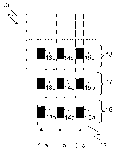
1, where Figure la provides a schematic perspective view of a body of rock to
be blasted,
and Figure lb provides a schematic sectional view of the same body of rock.
The body
shown generally at 10, has a series of boreholes 11a, lib, 11c drilled therein
and extending
from exposed face 12 in an upright, substantially vertical direction through
the rock.
Whilst Figure 1 illustrates substantially vertical boreholes, it will be
appreciated that this
orientation is merely for illustrative purposes, and other orientations than
substantially
vertical may be desired depending upon the circumstances of the blast site and
the design
of the blast. In one embodiment, the boreholes may form part of a ring of
boreholes
extending from the exposed face 12. The exposed face 12 may be in a drive or
other void
at the blast site.
Regardless, in a manner typical for blasting operations, the boreholes 11 a,
11 b, 11 c
extend into the rock in an upwardly direction from the exposed face 12 of the
body 10.
The boreholes 11a, 11b, 11c have sufficient depth for the loading therein of
more than one
explosive charge and may open into another drive or other void at their distal
ends or may
be blind. For the sake of illustration, three explosive charges are shown to
be loaded in
each borehole, with explosive charges 13a, 13b, 13c being loaded in borehole
11a,
explosive charges 14a, 14b, 14c being loaded in borehole 11 b, and explosive
charges 15a,
15b, 15c being loaded in borehole 11c. Explosive charges 13a, 14a, and 15a
each located
in adjacent boreholes may be considered to lie within a first layer 16 within
the body 10,
wherein layer 16 consists of a portion of rock directly adjacent face 12.
Likewise,
explosive charges 13b, 14b, and 15b lie within layer 17 of body 10 adjacent to
layer 16.
Finally, explosive charges 13c, 14c, and 15c lie within layer 18 of body 10
adjacent to
layer 17. Further boreholes, explosive charges and layers may also be present
although
these are not shown in Figure 1 for the sake of simplicity.
A respective detonator (not shown) is placed in operative association with
each
explosive charge such that actuation of each detonator causes actuation of its
associated
explosive charge. The detonators may be controlled via wired or wireless
communications
with an associated blasting machine, such that they are selectively actuated.
They may be
selectively actuated in groups, with each group corresponding to detonators
and explosive
charges located within each layer 16, 17, 18 in body 10. In this way, each
layer may be
CA 02772412 2012-02-28
WO 2011/038449 PCT/AU2010/001273
- 17 -
selectively fragmented in accordance with a desired sequence for the layers.
For example,
the blast operator may desire to actuate first those detonators and associated
explosive
charges 13c, 14c, and 15c located in layer 18 of body 10, at the distal ends
of the boreholes
11a, 11 b, 11 c relative to face 12, with subsequent actuation of the
explosive charges in the
other layers 16 and 17. The fragmented material may fall into a rise or other
void (not
shown) adjacent the illustrated body 10 and into the drive beneath exposed
face 12 for
extraction. The blast in layer 18 may result in a stranded portion of the rock
mass, for
example in the layers 16 and 17 and/or above the location of layer 18.
However, the layers
16 and 17 may still be blasted safely in a subsequent one or more initiation
events because
the boreholes have already been formal and loaded with explosive charges 13a,
14a, 15a
and 13b, 14b, 15b and had detonators placed in operative association with the
charges.
Thus, personnel access is not necessary.
In variations, given by way of example only, the layer 16 may be blasted
first,
leaving layers 17 and 18 as stranded portions of the rock mass but that may be
blasted
safely because they have already been prepared for blasting, or charges 14a-c
may be
initiated first to form a rise, followed by charges 13c, 15c to leave stranded
portions that
can still be blasted safely. Alternatively, all of the explosive charges in
boreholes 11 a and
11c may be initiated in one or more discrete initiation events, to leave a
pillar or column of
rock with charged borehole 1 lb through it. The pillar or column of rock may
be
fragmented at a later time by initiation the explosive charges 14a, b, c in a
subsequent
discrete user-controlled initiation event without personnel access.
In accordance with the methods disclosed, it is no longer necessary to drill
(boreholes), load the boreholes with explosive charges and associated
detonators, blast and
extract portions of rock in a progressive manner commencing with the portion
of rock
nearest the exposed face. Instead, all of the drilled boreholes are loaded
with explosive
charges and associated detonators and the charges, or groups or arrays of
them, are
initiated sequentially in discrete user-controlled initiation events. The
blast operator can
now choose which portions of rock are fragmented first, regardless of their
position
relative to the exposed face, in accordance with a desired blast plan.
As discussed, the detonators associated with the explosive charges may be
electronic and controlled by one or more associated blasting machines issuing
command
CA 02772412 2016-09-16
- 18 -
signals for the sequential initiation events. The command signals may take any
form,
including signals transmitted over a wired network or harness, or
alternatively they may be
wireless command signals communicated via any wireless means, including
electromagnetic signals such as radio signals. The use of wireless command
signals,
including the transmission of wireless command signals through the ground, has
been
proposed in, for example, international patent publications W02006/047823,
W02006/076777, W02006/096920, and W02007/124539.
The detonators associated with the explosive charges that are initiated in a
later or
subsequent one or more discrete user-controlled initiation events may be
caused to enter a
"sleep" mode prior to their initiation. The sleeping detonators (i.e. those
that have entered
a sleep mode) may remain in an inactive state for an extended period of time,
prior to their
subsequent actuation. In this way, the selected explosive charges and their
associated
detonators may be forced to enter a sleep period wherein the sleeping
detonators are unable
to actuate absent a special command signal.
Fragmented ore derived from blasting in the at least one initiation event may
be
extracted by automated (e.g. robotic) means, especially where the structural
integrity and
safety of the unsupported void is questionable.
The inventors have identified significant advantages to the combined use of
relatively stable explosives (such as bulk emulsion explosive materials or
other explosive
materials such as slurry explosives; ANFO; dynamites; black powder;
propellants) with
electronic detonators to extract stranded portions of the rock mass in a
subsequent one or
more of the at least two blast initiation events. For example, both emulsion
explosives and
electronic detonators, at least in selected embodiments, may be resistant to
degradation by
contact with water. Emulsion explosive materials may withstand extended
periods in a
borehole prior to actuation. Electronic detonators may comprise at least
substantially
sealed casings and / or be integrated into detonators assemblies that include
a housing to at
least substantially prevent egress of water and dirt. For example, electronic
boosters are
known in the art, which include a housing for containing a portion of
explosive booster
material, and a detonator in operable association with the explosive booster
material.
International patent publication W02006/096920, discloses a wireless
electronic booster
CA 02772412 2016-09-16
- 19 -
that is substantially sealed, that is robust for underground placement and
which is capable
of receiving wireless command signals, for example LF radio signals through
rock.
Thus, to summarise steps (a) to (c) occur in all of the rock mass to be
blasted in the
at least two initiation events, prior to conducting the at least two
initiation events in step
(d). Therefore, the invention includes embodiments in which the drilling and
loading of
the boreholes within what will become the stranded portion of the rock mass,
or the
"stranded ore", with emulsion explosives and electronic detonators occurs
before the
fragmentation and extraction of ore surrounding the stranded ore in the one
initiation
event. In this way, an entire volume of underground ore may be drilled and
loaded ready
for blasting, but only selected portions of the volume may be fragmented and
extracted by
way of an initial initiation event, leaving behind selected portions of
unfragmented ore for
example to help maintain the structural integrity of the underground void or
that are
otherwise stranded ore. However, since the selected portions of the
underground ore have
already been drilled and loaded with a combination of emulsion explosive
material and
electronic detonators, the detonators may be required to enter a "sleep mode"
and remain
inactive, possibly for an extended period, until the subsequent one or more of
the at least
two initiation events. Once the period has elapsed, a mine operator may then
choose to
fragment and extract the selected portions of unfragmented ore that were left
behind after
the initial blasting cycle. For example, a wireless command signal to FIRE may
be
transmitted from a blasting machine located at or above a surface of the
ground, through
the ground to the wireless electronic detonators located within the selected
portions of
unfragmented rock in association with emulsion explosives. In this scenario,
the pre-
loading of pillars or other support structures, or other stranded ore, with a
combination of
emulsion explosives and wireless electronic detonators permits the pillars and
support
structures to be "dropped" at a later date from a location above the ground,
without need
for personnel or equipment to be present in the underground blast site. If the
underground
blast site remains safe, in spite of the fragmentation of the pillars or other
support
structures, or other stranded ore, then the fragmented ore derived from
blasting the
stranded ore may then be extracted either by conventional or automated means.
CA 02772412 2012-02-28
WO 2011/038449 PCT/AU2010/001273
- 20 -
In selected embodiments, in step (a) of the method each borehole is drilled to
a
depth sufficient to be loaded in step (b) with more than one discrete charge
such that the
charges in adjacent boreholes form layers of discrete charges, and in step (d)
the detonators
and associated charges of each layer are selectively actuated, thereby to
fragment the rock
about each layer in the pillar or mass of rock according to a desired blasting
sequence for
the layers. For example, each layer of charges may comprise a substantially
planar array
of discrete charges located in adjacent boreholes, each substantially planar
array being
arranged about a plane generally perpendicular to the axis of the boreholes.
Each planar
array may be oriented at any angle relative to horizontal. For example, each
substantially
planar array may be arranged about a plane that is at least substantially
horizontal or
vertical, or a plane that intersects a horizontal plane at an angle of from 0
to 90 degrees. In
selected embodiments, at least some of the layers are blasted in a sequence
commencing
with a layer at the distil ends of the boreholes, with subsequent blasting of
layers retreating
towards the proximal ends of the boreholes. In this way, a void may be created
in the rock
at a location remote from the rock face, thereby to generate a support pillar
or other
support structure between the face and a new face created by blasting layers
in a retreating
sequence towards the proximal ends of the boreholes.
Still further embodiments include methods for extracting a body of ore
extending
above a drive formed across a lower portion of the body. Such methods are
encompassed
by and expand upon previously described embodiments of the invention, to
permit
extraction of a large volume of ore from a single drive, with reduced need for
multiple
drives, as will be evident from the following description and accompanying
figures. In
selected embodiments such methods further comprise forming at least one rise
in the ore
extending in a generally upward direction from the bottom drive whereby in
said one of the
at least two initiation events material from the body of ore adjacent the rise
is fragmented
and falls into the rise and the bottom drive for extraction via the bottom
drive, leaving a
void, and whereby in a subsequent one or more of the at least two initiation
events,
material of the body of ore is fragmented and falls at least partly into the
void.
Whilst this method, at least upon initial consideration, appears to be fairly
simple in
nature, the provision of a single drive to extract the entire body of ore is
enabled with only
one cycle of drilling and loading the boreholes, and placing the detonators,
by virtue of
CA 02772412 2012-02-28
WO 2011/038449 PCT/AU2010/001273
- 21 -
selective actuation of detonators. Further advantages of such methods, as well
as
additional steps, will become apparent from the following description of
Figures 2 and 3,
as well as of subsequent Figures.
Figures 2 and 3 provide a comparison of known techniques in the art for
extraction
(also known as stoping) of a body of ore extending upwardly in a slanting
direction, as
shown by each accompanying cross-section through the body A-A'. Whilst Figures
2 and
3 illustrate a slanting body of ore, this type of ore body is merely shown for
illustrative
purposes, and the methods disclosed herein will apply to a wide range of ore
body
orientations and configurations.
Figure 2a to 2h illustrate techniques that are known in the art for blasting
and
extraction of the body of ore shown generally at 30, which is located
underground and at
least substantially surrounded by other underground rock or material 31.
Figures 2a to 2h
show progressing in sequential events to fragment and extract the ore in a
series of stages,
commencing in Figure 2a with the formation of upper drive access 32 at the
centre-top
portion of body 30. In Figure 2b upper drive access 32 is expanded to form
upper drive
33. In Figures 2c and 2d the process is repeated, first by forming middle
drive access 34 in
Figure 2c, and then by expansion of middle drive access 34 to form middle
drive 35 in
Figure 2d. In Figure 2e cables and cable bolts are shown generally at 36 to
help shore up
slanting roof portion 37 of drive 35 (as shown in the cross-section A-A' of
Figure 2e).
In Figure 2f the process of drive formation is repeated once again, first to
form
lower drive access 38 and then lower drive 39. Boreholes 40 are subsequently
drilled into
the remaining body 30 by accessing the upper, middle, and lower drives (33,
35, 39).
Indeed, apparatus 41 is shown in the lower drive 39 in the process of drilling
boreholes 40
into a portion of body 30 located between lower drive 39 and middle drive 35.
Cross-
section A-A' illustrates how boreholes 40 are drilled in an upwardly slanting
direction,
generally in parallel with the general upward slant of the body of ore 30.
Next, as shown
in Figure 2g, selected boreholes adjacent the opposed blind ends of the
drives, loaded with
detonators and associated explosive charges (e.g. emulsion explosive charges)
are actuated,
for example by transmission to the detonators of a command signal to FIRE from
an
associated blasting machine. The result, as shown in Figure 2g, is the
fragmentation and
fall of rock around those boreholes into middle drive 35 and lower drive 39,
resulting in
CA 02772412 2012-02-28
WO 2011/038449 PCT/AU2010/001273
- 22 -
fragmented rock piles for extraction via the drives 35, 39 and drive accesses
34, 38 to form
narrow rises 42 clearly shown at one end in the cross-section A-A'.
Subsequently, as shown in Figure 2h, boreholes 40 immediately adjacent the
rises
42, and on opposite sides of them, are loaded and blasted and then adjacent
remaining
boreholes 40 are loaded and blasted in a retreating sequence, illustrated by
arrows 43.
Drives 33, 35, 39 are required to access and load the boreholes for each cycle
of blasting,
such that the retreating sequence of rock fragmentation can be achieved. Note
cross-
section A-A' in Figure 2h, which illustrates how the lower portion of body 30
between the
middle drive 35 and lower drive 39 is blasted in a retreating manner slightly
ahead of the
blasting of the upper portion of body 30 between upper drive 32 and middle
drive 35. In
this way, the fragmented rock tends to fall to the lower drive 39, the lowest
portion of the
underground blast site, for extraction via lower drive 39 and drive access 38.
Generally,
the extraction is by means of automated vehicle, as shown, since it is unsafe
for personnel
to pass beyond the brow, the outermost lower corner, of the remaining rock
mass at any
time.
In accordance with the prior art embodiments illustrated in Figure 2, multiple
drives are required to form the boreholes 40, and then to access and load them
at all levels
of the body 30, and sequential firing of the boreholes in a linear retreating
sequence is
required to maintain access to the ore body. The design of the underground
mine, and the
blasting and extraction sequence is driven by ore body geometry and drive
access, which
must be maintained through all stages of the operation to ensure accessibility
to the
boreholes for loading and proper communication with a blasting machine.
In contrast, the methods of the present invention permit loading of charges in
all
boreholes in a single cycle, with the option of multiple charges into each
borehole, with
selective control of the charges and associated detonators in at least two
user-controlled
initiation events.
Figures 3a to 3h show a progressive sequence of events for an exemplary
embodiment of a method of blasting or extracting rock from an underground
location, in
accordance with the teachings herein. For each figure, a cross-section A-A' is
provided to
aid understanding and orientation of the rock to be extracted. As for Figure
2, Figure 3
illustrates a body of ore extending at an upward slant relative to horizontal.
However, this
CA 02772412 2012-02-28
WO 2011/038449 PCT/AU2010/001273
- 23 -
arrangement is for illustrative purposes only, and the methods disclosed
herein may be
applied to many if not all other arrangements and orientations for the body of
ore.
With specific reference to Figure 3a, the body of ore is shown generally at
30, with
the rock surrounding or adjacent the body shown at 31. Only a single lower
access drive
38 and lower drive 39 is required to instigate extraction of the entire body
of ore 30.
Boreholes 40 are drilled from drive 39 in a generally upward direction along
the full length
of the drive 39 and the body of ore, for example by apparatus 41, such that
they extend for
a significant length to the upper regions of body 30. All the boreholes are
then loaded with
explosive charges (not shown), for example comprising emulsion explosives, in
multiple
decks separated by stemming and one or more detonators are placed in operative
association with the explosive charges. Preferably the detonators are wireless
as
previously described. As required, the charges are placed at pre-determined
locations
along the lengths of the boreholes. In preferred embodiments, the detonators
and
associated charges can be selectively actuated in groups, but as will become
apparent the
method of blasting comprises sequential initiation events by a blasting
machine, each of
one or more explosive charges across one or more boreholes and each a discrete
user-
controlled initiation event. Thus, for example, a user must act to initiate
each initiation
event at a desired time.
In Figure 3b, those detonators and associated charges within two selected
boreholes, each midway between the access drive 38 and the respective blind
end of the
drive 39, and optionally within adjacent boreholes, have been selectively
actuated to form
two upwardly extending rises or voids 51, 52 in the body 30, with fragmented
rock derived
from this initial blast falling into drive 39 to form piles 53, 54 for remote
extraction via
drive 39 and access drive 38. Those portions of the body of ore 30 beyond the
rises 51, 52
are of stranded ore. Subsequently, as shown in Figure 3c, without any
personnel accessing
the areas beyond rises 51, 52, those detonators and charges in boreholes 55
adjacent rise 51
are selectively actuated thereby to widen rise 51, again with the fragmented
material being
removed by remote control of the extractor.
In Figure 3d, detonators and charges at the upper, distal ends of boreholes 55
are
selectively actuated, such that fragmented rock falls to lower drive 39 via
void 51, thereby
to widen the upper portion of rise 51 by the retreat of the rock shown by
arrow 56. Again,
CA 02772412 2012-02-28
WO 2011/038449 PCT/AU2010/001273
- 24 -
the resulting fragmented rock is extracted from the site via lower drive 39
and drive access
38. By virtue of the methods disclosed herein, detonators and explosive
charges are
actuated at the distal ends of the boreholes, such that the resulting
fragmented rock can fall
into, and be extracted from, lower drive 39, so that the selective control and
actuation of
the detonators obviates the need for multiple drives at the underground mine
site. This is
because the methods disclosed herein circumvent the prior need to both load
and actuate
explosives in boreholes in a retreating sequence, to maintain safe physical
access. Instead,
the methods disclosed herein permit the detonators and associated charges to
be selectively
actuated, sequentially individually or in groups, regardless of their position
relative to an
open face or drive. This in turn opens the door to a wide variety of blasting
patterns and
sequences, one example of which is illustrated in Figure 3.
In Figure 3e, further selective actuation of groups of detonators has occurred
both
to widen initial rise 52, and to fragment rock adjacent boreholes extending
each side of
initial rises 51 and 52. In particular, layers of detonators and associated
charges in the
upper regions of body 30 associated with boreholes 56 have been actuated to
fragment
adjacent rock such that the resulting fragmented rock falls down (now widened)
rise 51
and into drive 39 for extraction. Likewise, layers of detonators and
associated charges in
the upper regions of body 30 associated with boreholes 57 and 58 have been
actuated to
fragment adjacent rock such that the resulting fragmented rock falls down (now
widened)
rise 52 and into drive 39 for remote controlled extraction. Lower layers of
detonators and
associated explosive charges associated with boreholes 55, 56, 57 and 58 have
also been
actuated, again to cause adjacent rock to fragment and fall into drive 39 for
remote
controlled extraction. Once again, the ability to selectively actuate the
detonators and
associated charges in groups, regardless of their position at the blast site
relative to the
drives, permits the body 30 to be fragmented and extracted in virtually any
desired pattern,
and extracted via lower drive 39. Remote controlled extraction of the
fragmented fallen
rock in drive 39 is required because the extractor vehicle is moving beyond
the nearest
brows 60 of stable rock to the access drive 38 without the rock in the void
beyond the
brows having been stabilised.
In Figure 3f, yet further selective actuation of the remaining detonators and
charges
in boreholes 55 has occurred, such that the stranded ore from the left side of
the body (as
CA 02772412 2012-02-28
WO 2011/038449 PCT/AU2010/001273
- 25 -
seen in the Figure) has been completely removed. Likewise, in Figure 3g yet
further
selective actuation of the remaining detonators and charges in boreholes 58
has occurred,
such that the stranded ore from the right side of the body (as seen in the
Figure) has been
completely removed. Essentially, a central column or pillar of unfragmented
ore 59
remains at the blast site, and this column may, if required for structural
reasons, be left in
place for an extended period, for example until mine personnel and equipment
have been
evacuated from the immediate proximity of the blast site. The detonators and
associated
charges located in column 59 may enter a sleep mode for an extended period
until a
suitable time to "drop" (i.e. fragment) and extract the column ore material.
Alternatively,
if the structural integrity of the site is of little or no concern, further
selective blasting of
upper layers of column 59 may quickly occur.
The selective blasting of the upper layers of column 59 and then of the
remaining
rock in the body of ore 30 is shown in Figure 3h. This is continued to
complete the
fragmentation and extraction of the entire body 30 from the blast site via the
single drive
39 and access drive 38.
Therefore, by comparing the sequence of events across Figures 2 and 3, it can
readily be seen that the methods disclosed herein present significant
advantages over those
of the prior art. The following steps in this embodiment of the invention,
which involve
selective actuation of detonators and associated charges in groups within
boreholes, greatly
widens the options available to a blast operator when designing the blasting
and extraction
sequence: (a) drilling boreholes in a generally upward direction from a lower
drive into the
body, or downwardly from an upper drive into a lower drive; (b) loading all
the boreholes
with at least one, and usually more than one, charge of explosive material
(e.g. emulsion
explosive material, or other relatively stable explosive material); (c)
placing detonators in
operative association with the charges; (d) forming at least one initial rise
in the ore
extending in a generally upward direction from the drive, optionally by
actuating
detonators and associated charges in at least one borehole; (e) selectively
actuating the
detonators and associated charges of an upper portion of the ore body at the
distal / upper
ends of the boreholes adjacent the at least one rise, thereby to fragment the
rock of the
upper portion such that the fragmented rock falls down the at least one rise
and into the
lower drive, for extraction via the drive. The methods include the selective
actuation of the
CA 02772412 2012-02-28
WO 2011/038449 PCT/AU2010/001273
- 26 -
detonators and associated charges in further portions in a progressive
sequence retreating
from said distal / upper ends of the boreholes adjacent the at least one rise,
thereby to
fragment the rock of the further portions, such that the fragmented rock falls
down the at
least one rise and into the drive, for extraction via the drive, thereby to
widen the rise.
Turning now to Figures 4 and 5, there is shown an example of drawbell firing
using
an embodiment of the method of the invention. A drawbell is a body of ore 100
that
expands upwardly and outwardly from the bottom of the body, where a bottom
drive 102 is
shown as having been formed. Thus, the body 100 tapers downwardly and
laterally,
relative to the length of the drive 102, to the drive.
Drawbell mining is a standard part of block cave mining and other large scale
underground mining methods. Typically, the drawbell, the body of ore 100, is
blasted in
two stages because the available void, the drive 102 and a rise 104 formed in
the body of
ore, is not sufficiently large to fire the drawbell in one blast without risk
of "freezing" the
fragmented ore.
Typically, the drawbell 100 is predrilled with boreholes (not shown for the
sake of
clarity) that extend in a series of fans or rings regularly spaced along the
body (in the
direction of the drive 102) from the bottom drive 102 to the top 106 of the
body, or
adjacent to the top. Thus, the outermost boreholes in each fan would extend
substantially
parallel to the inclined lateral faces 108 and 110 of the drawbell, while the
intermediate
boreholes will extend at gradually reducing angles to a central, approximately
vertical one.
The rise 104 is formed adjacent the lateral face 110 by loading one or more of
the
boreholes at that location with explosive charges and associated detonators,
and initiating
those charges. The fragmented material will fall through the resultant void
into the bottom
drive 102 for remotely controlled extraction or otherwise. At this stage, the
drive 102
beneath the drawbell 100 is still safe for personnel access because they may
pass through
the drive 102 without being beneath the void created by the rise 104.
Extracted material
may be removed from the bottom drive 102 by way of an access drive (not shown)
at the
left hand end of the drive 102 (in the Figure).
Traditionally, boreholes in the body of ore 100 to the side of the rise 104
remote
from the access drive would then be loaded with explosive charges and
associated
detonators and fired to fragment the whole body of ore, or a selected portion
of it, to that
CA 02772412 2012-02-28
WO 2011/038449 PCT/AU2010/001273
- 27 -
side of the rise 104. The fragmented material expands into the rise 104 and
falls into the
bottom drive 102. This is shown in Figure 5, with the fragmented material
referenced 112.
As the fragmented material falls into the bottom drive 102, a void 114 is
created above it.
Access to the remaining portion 116 of the body of ore closer to the access
drive is
prevented by the fragmented rock 118 in the bottom drive 102, and this must be
removed
remotely or otherwise prior to blasting of the portion 116.
Prior to the portion 116 being blasted, in the traditional procedure, the
boreholes in
it must be loaded with explosive charges and associated detonators. It will be
appreciated
that any reference herein to associated detonators includes locating them in
or adjacent the
explosive charges in the boreholes, wiring them in if they are not wireless,
and ensuring
they are in operative communication with an associated blasting machine.
A problem with clearing the fragmented rock in the bottom drive 102 beneath
the
ore portion 116 and loading the boreholes and associated detonators in the
portion 116 is
that the portion 116 is likely to have been damaged by the blast to create the
fragmented
material 112, leaving the portion 116 potentially as unsupported ground and
therefore
stranded ore even after the material 118 has been removed. This can make
accessing the
portion 116 to load the explosive charges and associated detonators risky
and/or contrary
to regulations. To overcome this, the portion 116 would have to be
structurally supported
and/or reinforced.
This difficulty is alleviated in accordance with the embodiment of the
invention by
loading the portion 116 with explosive charges and associated detonators
initially, that is at
the same time as the first portion of the body 100 to be blasted. As with the
detonators in
the first portion, the detonators in the portion 116 may be wired or wireless,
but are
advantageously wireless so as to alleviate risk of damage to their connection
to the blasting
machine(s) during the blasting of the first portion to create the fragmented
material 112.
The bulk emulsion explosive in the explosives charges in the portion 116
should
also be stable against desensitising as a result of the blast in the first
portion, preferably
requiring stable bulk emulsion explosives such as of the type previously
mentioned. The
emulsion explosives should also be sufficiently stable to not desensitise in
the time period
between the first stage blast and blasting the second portion 116. The delay
may be merely
for the time it takes to clear the fragmented material 118 in the bottom drive
102, including
CA 02772412 2012-02-28
WO 2011/038449 PCT/AU2010/001273
- 28 -
all or most of the fragmented material 112 as it continues to fall into the
bottom drive 102
as new void is created in the bottom drive by the removal of the material 118.
Alternatively, the blasting of the portion 116 may be delayed longer for any
technical, safety or commercial reason. During this time, no personnel access
should be
required beneath the portion 116. Likewise, the extraction of the fragmented
material 118
should be performed remotely. It will be appreciated from the above that the
blasting of
the portion 116 is a separate and sequential user-controlled initiation event
to the blasting
of the first portion resulting in the fragmented material 112. All of the
individual
explosive charges in each of these portions may be initiated together, that is
at the same
time or in a staged manner, or groups of them may be initiated as discrete
events.
The fragmented material from the portion 116 will fall into the void left by
the
fragmented material 112 from the first portion and into the bottom drive 102,
and may be
extracted remotely from the bottom drive 102 and the access drive.
Turning now to Figures 6 and 7, there is shown another variation of the
traditional
drawbell firing using an embodiment of the method of the invention. The
drawbell, the
bottom drive and the drilling of the boreholes as well as their loading with
explosive
charges and associated detonators is the same as in the method in accordance
with the
invention described with reference to Figures 4 and 5, so for convenience will
not be
described again. Furthermore, the same reference numerals have been used for
the same
parts.
The difference in Figures 6 and 7 over Figures 4 and 5 is that the sequential,
user-
controlled initiation events are separated horizontally rather than
vertically. In this
embodiment, therefore, the rise 120 is formed vertically in the centre of the
body of ore
100, and only from the bottom drive 102 to about half way to the top face 106.
This is
achieved by not firing detonators in the upper portion of the borehole(s)
around which the
rise 120 is folined. Depending on ground conditions, the rise 120 might go to
the full
height of the drawbell 100, that is to the top face 106. Furthermore, the rise
may be at any
other location within the body of ore 100, and/or there may be more than one
rise,
provided the desired outcome can be achieved.
The desired outcome of the first of the sequential, discrete user-controlled
initiation
events is shown in Figure 7. This is similar to Figure 5, except that it is
the lower portion
CA 02772412 2012-02-28
WO 2011/038449 PCT/AU2010/001273
- 29 -
of the body of ore 100 that is blasted first wholly around the rise 120 to
achieve the
fragmented ore 122. The fragmented ore is shown as having dropped into the
bottom drive
102 at 124, leaving a void 126 above the fragmented material 122 and below the
second
stage, unblasted portion 128 of the body ore 100.
The upper, second portion 128 of the body of ore is stranded ore, in the sense
that it
may have been damaged during the blasting of the lower, first portion, it is
unsupported
ground, and access to it is blocked by the material 122 and 124. Some or all
of that
material may be removed by remote extraction prior to blasting the second
portion 128, but
this may not be necessary at all since that material when blasted can fall
into the void 126.
If the fragmented material 122 and 124 from the first portion is removed
first, the
fragmented second portion 128 can fall directly into the bottom drive 102, at
least in part
for recovery by remote extraction. As in the embodiment of Figures 4 and 5,
the first and
second portions of the drawbell 100 can each be blasted at the same time or
over a time
period by a single initiation event or plural initiation events. However,
preferably each is
blasted in a single initiation event, with the two portions being blasted in
two sequential
discrete user-controlled initiation events.
This method could apply to multiple stoping methods, whereby vertical retreat
through multiple discrete initiation events can take place without human
access. It would
also be possible to develop "blind", up hole long hole rises using the same
methodology.
Figures 8 to 13 illustrate an embodiment of a method of blasting in accordance
with
the invention using stoping and backfilling. A common method of filling
underground
voids created by mining is to use fragmented rock or tailings fill with or
without cement
stabilisation. This fill material can become a source of ore dilution as
portions of ore
adjacent to the fill are extracted. This embodiment of the method of the
invention allows a
containment pillar of ore to be left in place to prevent dilution from the
fill while the
majority of the stope is blasted and mined in one or more discrete user-
controlled initiation
events. The containment pillar of ore is then blasted and mined in a
subsequent discrete
user-controlled initiation event.
Referring firstly to Figure 8, an ore body 150 is shown as having been
partially
mined to leave an open stope 152 that has been filled with backfill 154.
Traditionally, the
ore body 150 is mined by a retreat mining, with the fragmented ore (from the
left hand end
CA 02772412 2012-02-28
WO 2011/038449 PCT/AU2010/001273
- 30 -
of the ore body in the Figures) being extracted from a bottom drive 156
through an access
drive 158 and the backfill being introduced to the open stope 152 by way of
another access
drive 160 (both access drives are illustrated schematically) and an upper
drive 162.
In current practice, the blasting of the ore body 150 may be as described with
reference to Figures 2a to 2h from one end of the ore body 30, for example as
shown at the
left hand end in Figures 2g and 2h, albeit with only the upper and lower
drives 162 and
156. Thus, all of the boreholes in the ore body 150 may be drilled prior to
blasting any of
the ore body, but only those boreholes in the portion of the ore body to be
blasted in a
single discrete initiation event are loaded with explosive charges and
associated detonators.
Prior to each initiation event, the fragmented material from any previous
initiation
event is extracted via the bottom drive 156 and access drive 158 and the
resultant void
alongside the remaining ore body is filled with backfill, for example and for
present
purposes only, as illustrated in Figure 9. It is then necessary to remove some
of the
backfill by way of the bottom drive 156 and access drive 158 in order to
create a void into
which newly blasted material can fragment, as illustrated at 164 in Figure 8.
However, the
newly blasted material will then mix with the backfill, with the result that
some of the
fragmented ore is lost.
The embodiment in accordance with the invention is illustrated in Figures 9 to
13.
In this embodiment, in Figure 9 the backfill is illustrated as filling the
open stope 152 and
hard up against the adjacent end 166 of the ore body 150. As before, all of
the boreholes
may be drilled through the entire ore body from the bottom drive 156 to the
upper drive
162 or adjacent to it (from the first blast in the ore body 150 resulting in
the start of the
open stope 152 or from the first blast to occur from the stage illustrated in
Figure 9).
Likewise, in accordance with the invention, all of the boreholes may be loaded
with
explosive charges and associated detonators, preferably wireless detonators,
or, less
conveniently, only those boreholes in, for example, the left hand end of the
ore body 150
illustrated in Figure 9 may be loaded, in either case to perform two or more
sequential, but
not necessary consecutive, discrete user-controlled initiation events. As
shown in Figure 9,
a rise 168 is formed through the ore body 150 from the bottom drive 156 to the
top drive
162 at a distance spaced from the existing end face 166 sufficient to form a
pillar 170 (see
Figure 10) to support the backfill and minimise contamination of the rest of
the ore body
CA 02772412 2012-02-28
WO 2011/038449 PCT/AU2010/001273
-31 -
when it is blasted. The rise 168 may be formed by blasting the explosive
charges in one or
more boreholes.
Referring to Figure 10, part of the ore body 150 to the side of the rise 168
remote
from the end face 166, and part of the ore body on the same side as the end
face 166 are
blasted in one or more discrete user-controlled initiation events to fragment
those parts of
the ore body, as shown at 172 and leave the residual pillar 170.
As noted above, in addition to the boreholes in the pillar material 170, the
boreholes blasted in this phase may be the only ones loaded with explosives
material and
associated detonators. Alternatively, the boreholes in the residual portion
174 of the ore
body may also have been loaded with explosive charges and associated
detonators to await
one or more separate initiation events.
In Figure 11, the fragmented material 172 has been removed by means of a
remote
extractor (not shown) through the bottom drive 156 and associated access drive
158,
leaving the pillar 170 of stranded ore supporting the backfill material 154,
and therefore
the extracted ore material 172 at least substantially free of contamination by
the backfill
material.
In Figure 12, the preloaded material of the pillar 170 is blasted without
separate
personnel access, to produce the fragmented pillar material 176. This is in
contact with the
backfill material 154, and will therefore be at least partly contaminated by
the backfill
material when it is extracted through the bottom drive 156. However, it has a
much
smaller volume than would have been the case for the fragmented ore body
material 172
without the presence of the pillar 170.
After removal of the fragmented material 176, the residual ore body 174 could
be
blasted in a traditional retreat sequence, following loading with explosive
charges and
associated detonators if that has not already occurred. However, as shown in
Figure 13,
the mined open stope 152 needs filling with backfill, and it is simplest to do
this from the
portion of the upper drive 162 above the residual ore body 174. Backfilling
will continue
until the open stope 152 is filled, that is until the new backfill material
meets the existing
backfill material 154. The sequence of forming a pillar and blasting the
adjacent material
and then the pillar may then be repeated.
CA 02772412 2012-02-28
WO 2011/038449 PCT/AU2010/001273
- 32 -
Whilst the present invention has been described with reference to specific
embodiments and specific methods for blasting, it will be appreciated that
such
embodiments and methods are merely exemplary, and other embodiments and
methods
other than those described herein, will be encompassed by the invention as
defined by the
appended claims. In particular, features of any one embodiment described above
may be
applied mutatis mutandis to any other embodiment, and this description should
be read
accordingly.
The reference in this specification to any prior publication (or information
derived
from it), or to any matter which is known, is not, and should not be taken as
an
acknowledgment or admission or any form of suggestion that that prior
publication (or
information derived from it) or known matter forms part of the common general
knowledge in the field of endeavour to which this specification relates.