Note: Descriptions are shown in the official language in which they were submitted.
CA 02772545 2017-01-27
NERASTRUCT ME MONITORING DEVICES, SYSTEMS, AND METHODS
Background
1. Field of the Invention
The invention is directed to devices, systems, and methods of monitoring- and
controlling an infrastructure such as, but not limited to the supply and use
of
commercial, industrial or residential water, gas and/or electric, and, in
particular, to
devices, methods, and systems for monitoring and controlling a municipality
and
alerting a user to potential faults and actions required.
c 2. Background of the Invention
Municipalities ad-minister and/or outsource numerous utility and safety
systems within each municipality. Such systems are usually complex
infrastructures
and include but are not limited to water distribution, gas distribution,
electricity
distribution, waste management, traffic control, tire departments, police
departments,
and emergency response departments. Each of these systems needs to be
monitored
for use (authorized or unauthorized), faults, tampering, events, leaks,
contamination,
and/or other issues.
Often to obtain an understanding of the state of any one system, or for
billing
or repair purposes, personnel must be sent into the municipality to manually
cheek for
problems within the system. This is slow, labor-intensive process can lead to
overlooked problems. Furthermore, preferred aspects of the system may only be
evaluated irregularly or infrequently, thereby allowing a problem to go
unchecked for
long periods of time. For example, a leak in a water main may cost a water
company
a significant amount of money in lost water, energy usage, and chemical
treatment,
particularly if the leak is not discovered for a long period of time.
Furthermore, a leak
cart lead to underground structural erosion.
Another problem and disadvantage associated with current systems is the lack
of property rights sufficient to maintain a network of monitors and device
controllers
capable of creating a transmission infrastructure that can adapt to multiple
monitors
CA 02772545 2011-11-16
WO 2010/135587
PCT/US2010/035666
and controllers and form an information network for providing information
about the
system to the utility monitoring the network. For example, some networks
require
new polls or towers to be erected for placement of the communication devices
or
municipalities may have to rent space on a utility company's poles.
Furthermore, an issue in one system may cause an issue in another system.
For example, a fire reported to the fire department may require the as company
to.
shut off gas flow to the vicinity of .the fire and require the water company
to redirect.
water OT additional water pressure to the vicinity, However, current systems
are not
interoperable. Therefore, it is desirable to have a single system that can
monitor
.. different aspects of at least one municipality system continuously and
communicate
.with several entities at the same time.
Summary of the invention
The present invention overcomes the problems and disadvantages associated
with current strategies and systems and provides new systems and methods of
monitoring municipality infrastructure.
One embodiment of the invention is directed to an infrastructure monitoring
system. The system comprises an operations center and a. plurality of
communications devices communicatively coupled to the operations center.. At
least
one communications device of the plurality of communications devices is
coupled to a
component of the infrastructure, and at least two communications devices are
monitoring devices. The first monitoring device monitoring a first aspect of
the
infrastructure and the second monitoring device monitoring a second aspect of
the
infrastructure.
In the preferred embodiment each monitoring device is comprised of at least
one sensor sensing at least one condition within the infrastructure, a data
storage
device storing data sensed by the at least one sensor, a transceiver device
adapted to
transmit arid receive data, and a processor communicatively coupled to at
least one
sensor, the data storage device, and the transceiver device.
In a preferred embodiment, the operations center and the plurality of
.. communications devices are wirelessly communicatively coupled. Preferably,
at least
one communications device is an output device. The output device comprises a
transceiver device adapted receive or transmit data, at least one output port,
and a
processor communicatively coupled to at least one of the transceiver device
and at
least one output port.
7
CA 02772545 2011-11-16
WO 2010/135587
PCT/US2010/035666
In a preferred embodiment, the operations center and at least one output
device are wirelessly communicatively coupled. Each communications device is
preferably adapted to receive transmissions for a second communications device
and
retransmit the transmission to the second communications device. Each
communications device is preferably adapted to receive transmissions for the
operations center and retransmit the transmission to the operations center.
In a preferred embodiment, at least one output device is coupled to at least
one
of an actuator control device, an alarm, a Radio-Frequency- identification
device and a
tamper prevention device,
In a preferred embodiment, a monitoring device and an output device are
contained within the same unit. The monitoring device and the output device
preferably share at least one of a power source, a transceiver device, and a
processor.
The infrastructure can be at least one of a water distribution system, an
electricity distribution system, a gas distribution system, a traffic control
system, and
an emergency response system. 711.e system can monitor for at least one of use
of gas,
water, electricity,, tampering, leaks, UPS location, proximity, tilt, smoke,
temperature,
rust, corrosion, fluid flow, pressure, water quality, air quality,
contamination, pH,
infrastructure status, and motion.
In a preferred embodiment, the system produces an alert when at least one
.20 monitoring device registers an event. In a preferred embodiment, at
least one
monitoring device is coupled to a visual or acoustical device. The operations
center
can comprises muthiple operations centers. Preferably each operations center
is
uniquely located. The operations center can monitor a plurality of
infrastructures
concurrently,
Preferably, the plurality of infrastructures are selected from the group
consisting of water systems, electrical systems, gas systems, emergency
response
systems, traffic control systems, and combinations thereof Preferably,
component of
the infrastructure is one of a fire hydrant, a utility meter, a manhole cover,
a utility
pole, a valve, a pipe, a traffic light, water tower, water tank, valve box,
valve box
cover, .meter box, meter box cover, and a smoke detector. In preferred
embodiments
where the component of the infrastructure is a fire hydrant, the
communications
device can be coupled to the fire hydrant is a repeater, at least one portion
of the fire
hydrant can be comprised of a material that does not interfere with the
communications and/or the communications device coupled to the fire hydrant
can be
3
CA 02772545 2011-11-16
WO 2010/135587
PCT/US2010/035666
positioned within one of the nozzle cap, the pumper nozzle, the hose nozzle,
the fire
truck hookup, and the bonnet.
Another embodiment of the invention is directed to another infrastructure
monitoring system. The system comprises an operations center and a plural.ity
of
communications devices communicatively coupled to the operations center. At
least
one communications device of the plurality of communications devices is
coupled to a
fire hydrant, a valve, a valve box, a valve box cover, a meter, a meter box, a
meter
box cover, a water tower, a water tank, a pumper nozzle, a hose nozzle, or a
manhole
cover.
in a preferred embodiment, the communications device coupled to the fire
hydrant is one of a monitoring device, an output device, and a repeater.
Preferably, at
least one portion of the fire hydrant is comprised of a material that does not
interfere
with the communications. In a preferred embodiment, the communications device
coupled to the fire hydrant is positioned within one of the nozzle capõ the
pumper
nozzle, the hose nozzle, the fire truck hookup.
and the bonnet.
Another embodiment of the invention is directed .to a .fire hydrant. The fire
hydrant comprises a bonnet and a communications device coupled to the bonnet.
The
communications device is an element of a infrastructure monitoring system.
Other embodiments and advantages of the invention are set forth in part in the
description, which follows, and in part, may be obvious from this description,
or may
be learned from the practice of the invention.
Description of the Drawings
The invention is described in greater detail by way of example only and with
reference to the attached drawings, in which:
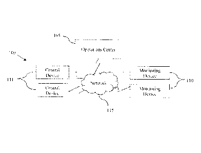
Figure 1 is a schematic of one embodiment of the system of the invention.
Figure 2 is a schematic of one embodiment of the monitoring device of the
invention.
Figure 3 is a schematic of one embodiment of a control device of the
invention.
Figures 4a-b are images of one embodiment of a device of the invention
housed within a fire hydrant.
Figures 5a-b are images of an embodiment of a insulation device for sealing
the bonnet of the fire hydrant from. the water within the fire hydrant.
Description of the Invention.
4
CA 02772545 2011-11-16
WO 2010/135587
PCT/US2010/035666
As embodied and broadly described herein, the disclosures herein provide
detailed embodiments of the invention. However, the disclosed embodiments are
merely exemplary of the invention that may be embodied in various and
alternative
forms. Therefore, there is no intent that specific structural and functional
details
should be limiting, but rather the intention is that they provide a basis for
the claims
and as a representative basis for teaching one skilled in the art to variously
employ the
present invention.
A problem in the art capable of being solved by the embodiments of the
present. invention is monitoring and maintaining an infrastructure. It has
surprisingly
been discovered that monitoring devices with one or two way communication
abilities
can be used to detect faults in the municipality's systems and provide on-
demand, real
time, or near real time device status, maintenance, and control over the
systems.
.A network of monitoring devices of the invention is capable of providing, a
system administrator with a full picture of the current state of the system.
The
network preferably includes an array of different monitoring devices each
capable of
sensing at least one condition. The monitoring devices may be capable of
sending
and receiving data to and from at least one operations center. Communication
may be
from the remote monitoring device to a central monitoring facility, to one of
a number
of regional monitoring centers, to a user, and/or to a research facility.
Furthermore,
the system preferably includes at least one control device. Each control
device is
adapted to control a different aspect of the system. The control devices may
be pan
of the .monitoring devices or may be separate units. Communication is
preferably
over the Internet, but may be over a private network, a local area network, or
a wide
area .network. Preferably the communication involves a wireless component,
such as
from the remote monitoring device and/or control device to a regional
monitoring
facility, or to distributed monitorsõkiso preferably, the communications are
secured
or encrypted such that the communications system cannot be monitored by
another
unknown party. Preferably access to the system is granted through user names
and
passwords, although additional and/or alternate encryption methods can be
employed.
30. One embodiment of the invention is directed to water infrastructure
systems.
In such systems, monitoring devices can be located throughout the system, for
example, as attachments to component parts, for feedback to a network that can
provide real-time information to the utility operating the network. The
network
operators can use the information transmitted to activate controlling devices
on the
5
CA 02772545 2011-11-16
WO 2010/135587
PCT/US2010/035666
network, or to dispatch repair or other services as directed by the
information
provided by the network. For example, if water pressure monitors on a water
meter
indicate a variance between locations, a water leak can be reported using, the
network,
and controlling devices can divert water. Pressure meters can be attached to
tire
hydrants to monitor and report pressure losses throughout the system,
providing real-
time information to benefit the users of the fire hydrants (fire departments
who need.
to be assured of adequate pressure), the users of the system (water consumers
who
will be affected by lower pressure), and the operators of the system (who
sutler asset
loss as a result of lack of real-time information about losses).
Figure 1 depicts a system 100 of the invention for monitoring, controlling,
and
communicating with at least one monitoring device andfor at least one control
device.
System 100 includes an operations center 105 in communication with at least
one
monitoring device 110 and/or one control device 1-11. In the pre.ferred
embodiment,
there is bi-directional communication between operations center 105 and
devices 110
and 11.1. Communications can be simplex or duplex. Communication can occur
over
any communication.s network 115 known in the art, including but not limited to
wired
networks, .wireless networks, Zigbee networks, Bluetooth networks, Z-wave
networks, WiFi networks, .WiMax networks, RF networks, local area networks
(LAN), internet networks, wide area networks (WAN), cellular telephone
network,
hardwired telephone networks, 900 MHz wireless networks, and satellite
networks.
In the preferred embodiment, the network is a fixed network. .For example, the
fixed.
network can be a mesh network or a star network* Additionally, devices 110 and
1.11
and operations center 105 can be in direct communication or can communicate
through an intermediary device, such as a relay, a repeater, a gateway, or
other device
.25 capable of receiving and retransmitting a message.
Each monitoring device 110 of the invention preferably monitors at least one
aspect of the infrastructure. The monitored aspect can be one or more of the
components of the infrastructure (e.g. pipe conditions, valve conditions.,
fire hydrant
conditions, service line conditions, meter conditions, power line conditions,
and
battery conditions), commodity conditions (e.g. fluid or gas flow, fluid or
gas
pressure, fluid or gas temperature, and fluid or gas contaminants), or
combinations
thereof Additionally, the monitors can be self monitoring. For example the
monitors
preferably determine if there is a loss of communication, low battery levels,
and/or
internal damage (e.g. short circuits due to water damage). Additionally, each
6
CA 02772545 2011-11-16
WO 2010/135587
PCT/US2010/035666
monitoring device 110 can be structurally stable (e.g. fixed to a valve, pipe,
utility
pole, a hydrant, a .valve box, a valve box cover, a meter, a meter box, a
meter box
cover, a water .tower, a water tank, a pumper nozzle, a hose nozzle, or an
manhole
cover) or .movable (e.g. allowed to move with or within the flow of water or
gas in the
pipes).
For example, a device 110 or 111 can be coupled to a .fire hydrant:, see
Figures
4a-b. The device 110 or .1 I 1 can be located within the nozzle cap (i.e. in
the pumper
nozzle, .the hose nozzle, or in the fire truck hook up), within the body of
the fire
hydrant, within the bonnet, attached to the outside of the fire hydrant, or at
another
location on or within the fire hydrant. Preferably, the housing for the device
110 or
1 1 1 is made of plastic, nylon, other synthetic or natural materials, or any
other
material that does not block transmissions to and from the device 110 or 111.
The
bonnet of the .fire hydrant can be isolated from the .flow of water within the
fire
hydrant, see Figures 5a-b. For example, there can be a plastic, metal, or
other
material disc that seals off a portion of the fire hydrant to prevent water
from reaching
the interior regions of the bonnet.
Each node in the network of the invention preferably detects errors in
transmissions. Error detection can use cyclic redundancy codes using a table
based on
a defined polynomial or any other method of error detection. In preferred
embodiments, transmissions can be rerouted if the primary .route is blocked,
or
otherwise unavailable. Furthermore, devices 1.10 and 111 can confirm receipt
of a
message, e.g. via a hand shake protocol. In instances where confirmation is
not
received the message can be resent along the same rout or rerouted.
In preferred embodiments, each monitoring device 110 and each control
device 1 1 1 is assigned a unique identifier. The unique identifier can be
related to the
devices' geographical locations, street addresses, order of installation, or
any other
.method of identifying the devices. Furthermore, different types of devices
110 and
111 can have identifiers that are unique to that type of device. For example,
the
identifier for all water meters can start with a WM. while .the identifier for
all leak
detectors can start .with a LB. Each communication .to and from a device 110
and 111
can include the unique identifier so that the message is received by the
correct device
110 or 111, or operations center 105 can determine where the message was sent
from.
Each monitoring device 110 and each control device 111 can be retrofitted to
an existing system or device, can be coupled to a new system or device, or can
be
7
CA 02772545 2011-11-16
WO 2010/135587
PCT/US2010/035666
integrated into a new system or device. For example, the system can be
connected to,
work with, or work independently of a Supervisory control and data acquisition
(SCAM) network. In preferred embodiments, each monitoring device 110 and each
control device 111 has a set of adapters to facilitate coupling the monitoring
device
110 or control device 111 to a new or existing system or device.
In preferred embodiments, system 100 is divided into sectors with each sector
having at least one monitoring device 110 and/or at least one control device
111.
.Each sector can communicate directly with operations center 105 or each
sector can
have at least one intermediary communications device .that is in communication
with
.. the monitoring device ii 0 and/or control device 111 and operations center
105. In
the preferred embodiment, .the sectors are divided up by geographical
location. For
example, all of the devices in one neighborhood can be in a. single sector and
there is
one sector for each neighborhood. In preferred embodiments, one intermediary
communications device can service multiple sectors.
in preferred embodiments, each monitoring device 110 and/or control device
11.1 can communicate with adjacent monitoring devices 110 and/or control
devices
Ill. In such embodiments, each device 110 and/or Ill can act as a transceiver
or
relay by receiving messages intended for another device or for the operations
center
105 and forwarding the message. In embodiments where the system 100 is
divided.
into sectors, monitoring devices 11. 0 and control devices -111 can only
communicate
within their sector. In other embodiments, monitoring device 110 and control
device
111 can communicate with devices 110 and/or 111 in other sectors. Each remote
monitoring device 110 and/or the operations center 105 may be able to
determine if a
transmitted message was received by the intended device and, if not, may be
able to
reroute the message until the message is properly received. Additionally,
relay
devices can be implemented in the system to further extend the ranee of
communications.. For example, relay devices can be placed on utility poles, on
municipal buildings, within fire hydrants, and/or under manhole covers. In
preferred
embodiments, devices 110 and. 111 communicate over a mesh network. In the mesh
network, devices 110 and 11.1 can communicate with other devices 110 and 111
within the mesh network. Operations center 105 can set specified
communications
pathways derived from routing tables.
Operations center 105 can be located at a municipality office, a private or
public company, a fire station, a police station, or any other entity that
monitors
8
CA 02772545 2011-11-16
WO 2010/135587
PCT/US2010/035666
operations center 105. In other embodiments, operations center 105 can be a
remotely
hosted operations center accessible by a device capable of accessing the
Internet. In
such embodiments, operations center 105 can take advantage of cloud computing
(e.g.
a network of remotely hosted computers, servers, and data storage devices.).
.. Compared to non-remotely hosted computer networks, cloud computing can
increase
ease of use, increase access, increase security, decrease costs, be custom
tailored, and
provide an .unrestricted expansion of storage space. Additionally, in
preferred
enibodiments, there is a plurality of operations centers 105. One or more
operations
centers can he located at different entities and each control center can
monitor a
different aspect of system 100. For example, in embodiments where one
monitoring
device monitors water usage and another monitors gas leaks, the water usage
aspect
can be monitored by a water utility company and the gas leaks can be monitored
by
the gas utility company and/or the fire department. in preferred embodiments,
there
are redundant operations centers 105, where at least two operations centers
105
monitor the same aspect of system 100. Operations center 105, in preferred
embodiments, can send transmissions to update the .firmware of devices 110 and
111.
Figure 2 is a schematic of a monitoring device unit 200. Monitoring device
.unit 200 includes a processor 205. Processor 205 is coupled to at least one
input port
210 for receiving data from sensors 215. Processor 205 is also coupled to a
transceiver 220 for sending and receiving signals. In preferred embodiments,
processor 205 is coupled to a data storage unit 230. Data storage unit 230 can
hold a
predetermined amount of data received from the sensors 215. For example, data
storage unit 230 can hold data for a predetermined amount of time (e.g. one
day, one
week, or one month), can hold a predetermined number of readings (e.g. .10
readings,
100 readings, 1(100 readings), or can hold. data until directed to purge .the
data by the
operations centerõAdditionally, data storage unit 230 can hold instructions
for
processor 205 to execute upon prompting from the operations center. In the
preferred
embodiments, processor .205 compiles at least some of the data stored in data
storage
unit 230 for transmitting to the operations center.
Each remote monitoring device 200 may collect data and/or transmit data
continuously, at specific intervals, or randomly. in embodiments where the
monitoring device 200 collects and transmits data in a non-continuous
configuration,
monitoring device 200 may turn off or reduce power consumption during the non-
data
collecting periods to save energy. in preferred embodiments, processor 205 is
9
CA 02772545 2011-11-16
WO 2010/135587
PCT/US2010/035666
coupled to a power source 235. Power source 235 can be a device capable of
powering processor 205 and devices attached to processor 205. For example,
power
source .235 can be a battery, solar panel array, wind turbine., water
.turbine, electrical
hues, or combinations thereof. In preferred embodiments, .there is also a
backup
power source, such as a battery. .In preferred embodiments, the power may
derive
from the operation of the infrastructure system.
In the preferred embodiment, processor 205 is coupled to at least one sensor
215 that monitors at least one condition associated with the monitoring
device. In
preferred embodiments, sensors 21.5 can determine .the status of a device.
Sensors
.215 can be directly wired to processor 205 or can use wireless communication
to send
and receive signals from processor 205. Sensors 215 can be positioned within
the
monitoring device or be external to the monitoring device. In preferred
embodiments,
sensors 215 are positioned remote from the monitoring device. For example a
sensor
can be positioned in a fire hydrant, on a nearby building, or on a utility
pole. In the
embodiments, where sensors 215 and processor .205 communicate wirelessly, the
same communications protocol can be used in the sensor/processor communication
as
in the processor/operations center communication, or different communications
protocols can be used. in the sensor/processor communication as in .the
processor/control center communication. For example, the sensor/processor
.. communications can use RI' .protocols While the processor/control center
communications can be over a wired network.
In preferred embodiments, sensor 21.5 is a use monitor. In such embodiments,
the use monitor records the amount of water, gas, electricity, or other
commodity that
is used by a customer over a specified period of time. The use monitor can.
15 continuously record the amount of the commodity used or the use monitor
can
provide a signal to processor 205 that the commodity is in use. Processor 205
can
transmit a signal to the operations control to alert the operations center
that the
monitoring device is being used and/or how much of the commodity is flowing
through the sensor. In preferred embodiments, the operations center can
request a
reading from the use monitor on demand. in preferred embodiments, the
processor or
the operations center can determine based on the use, if there is unauthorized
use of
the commodity. Upon detection of .unauthorized use, at least one of processor
205 or
the operations center can generate an alarm that there is unauthorized use.
For
example, in embodiments where the use monitor is coupled to a fire hydrant, if
the
CA 02772545 2011-11-16
WO 2010/135587
PCT/US2010/035666
use monitor indicates that the fire hydrant is in use, however no fire is
reported, the
operations center can disseminate an alert that there is potential misuse of
the fire
hydrant.
In preferred embodiments, at least one sensor 215 is a tamper sensor. The
tamper sensor can be a motion detector, a contact sensor, a rotation sensor, a
touch
sensor, a proximity sensor, a biofeedback sensor, a temperature sensor, a
capacitance
sensor, a resistance sensor, or any other sensor that is able .to detect the
presence of an
object. The tamper sensor can send a message to processor 205 when the tamper
sensor detects an event. The processor 205 will then evaluate the event to
determine
if a device being monitored is being, tampered with or will relay the message
to the
operations center for evaluation. The monitored device can be a fire hydrant,
utility
meter, valve, manhole cover, pump, or any other device that may be tampered
with.
Upon detection of a tamper event, at least one of processor 205 and the
operations
center can generate an alarm .that the device is being tampered with. In
preferred
embodiments, the monitoring device may activate a tamper prevention device
(described below). In preferred embodiments, the operations center will send a
transmission to processor 205 telling processor 205 to disregard messages from
the
tamper sensor for a predetermined period of time or until another message is
received
from the operations center telling processor 205 to resume monitoring for
tamper
events. For example, if a fire department needs to use a fire hydrant, the
operations
center will send a messageTo processor 205 to temporarily disregard any tamper
events. Once the fire department is finished using the .fire hydrant the
operations
center will send a message to processor 205 to start monitoring for tamper
events
again.
75 in preferred embodiments at least two of sensors 215 are leak detectors.
Each
leak. detector can include an in-pipe leak detector and/or an exterior leak
detector. In
gas applications, the leak detectors are preferably vapor sensors. While in
liquid
applications, preferably the leak detectors use acoustic monitoring to
determine
presence and location of a leak.. The energy generated from a leak is
transmitted
within a pipe through the commodity as .well as through .the pipe wall.. Each
leak
detector can detect the vibrations made by the leak in the commodity or the
pipe wall,
joint or service line. To determine the location of a leak, at least two
detectors must
detect the same leak. Based on the velocity of the sound traveling along the
pipe (V),
the distance between the two detectors (I)) and the delay between the times
each
.1
CA 02772545 2011-11-16
WO 2010/135587
PCT/US2010/035666
detector detects the sound (T), the location of .the leak (1,) can be
determined by the
following equation:
-- (I) - (V x
When using the above equation, the typical velocity of sound in water is about
1500
m/s while the typical speed of sound through an iron pipe is 5100 m/s. The
.veloeity-
can be measured empirically. For example, if the .leak is exactly midway
between the
two detectors the sound would reach both detectors at the same time. Each
detector
may monitor continuously or at predetermined periods of time. The leak
detectors
can send a message to processor 205 when the leak detectors detect an event.
The
processor 205 can then evaluate the event to determine if there is a leak arid
how
severe the .leak is or can relay the message to the operations center for
evaluation.
Upon detection of a leak event, at least one of processor 205 or the
operations center
can generate an alert that there is a leak if the leak is determined to be
severe enough
to warrant attention.
Is In preferred embodiments, at least one sensor .215 is a smoke detector.
The
smoke detector can be a photoelectric detector., an ionization detector, or
any other
device that can detect the presence of smoke. The smoke detector can be
located
within the monitoring device or exterior to the monitoring device. In the
preferred
.embodiment, the smoke detector monitors continuously for smoke. The smoke
detector can send a message to processor 205 when the smoke detector detects
an
event. The processor 205 can then evaluate the event to determine if there is
smoke
or can relay the message to the operations center for evaluation. Upon
detection of
smoke, at least one of processor 205 or the operations center can generate an
alert that
there is smoke.
In preferred embodiments, at least one sensor 215 is a temperature sensor.
The temperature sensor can be a contact sensor (e.g. thermocouples,
thermistors,
liquid-in-glass thermometers, resistance temperature detectors, filled system
thermometers, bimetallic thermometers, semiconductor temperature sensors, arid
phase change indicators) or a non-contact sensor (e.g. radiation thermometers,
thermal
imagers, ratio thermometers, optical pyrometers, and fiber optic
thermometers). The
temperature sensor can be located within the monitoring device or exterior to
.the
monitoring device. In the preferred embodiment, the temperature sensor
.monitors
continuously for the temperature to rise above or drop below a predetermined
threshold. The ..temperature sensor can send a .message to processor 205 when
the.
1.2
CA 02772545 2011-11-16
WO 2010/135587
PCT/US2010/035666
temperature sensor detects a temperature beyond the thresholds. The processor
.205
can then evaluate the event to determine if there the temperature is a problem
(such as
freezing pipes or fire) or can relay the message to the operations center for
evaluation.
Upon detection of .undesirable temperatures, at least one of processor 205 or
the
operations center can generate an alert that there is an undesirable
temperature
condition.
In preferred embodiments, at least one sensor 215 is a rust and/or corrosion
sensor. The sensor can detect rust and/or corrosion using any method known in
the
art, including but not limited to liquid penetration inspection, magnetic
particle
inspection, radiographic inspection, visual inspection, eddy current
inspection,
ultrasonic inspection, and thermographic inspection. The sensor can send a
message
to processor 205 when the sensor detects a rust or corrosion beyond a
threshold value..
The processor 205 can then evaluate the rust or corrosion to determine if
there is a
problem or can relay the message to the operations center for evaluation. Upon
detection of undesirable rust or corrosion, at least one of processor 205 or
the
operations center can generate an alert that there is an undesirable amount of
rust or
cormsion.
In preferred embodiments, at least one sensor 215 is a fluid flow sensor.
Fluid
flow sensor can be .used either in gas systems or liquid systems. The fluid
flow sensor
can detect direction of the flow, turbidity of the flow, velocity of the flow,
density of
the flow, viscosity of the flow, and/or any other aspect of the flow. The
fluid -flow
sensor may be a velocimeter, a laser-based interferometer, a vane, a rotary
potentiometer, a Hall effect sensor, a device to measure heat .transfer caused
by the
flowing fluid, or any other device know in the art to measure the flow of
fluid. The
sensor can send a message to processor 205 when the sensor detects a flow
anomaly.
The processor 205 can then evaluate the event to determine if the anomaly is a
problem or can relay the message to the operations center for evaluation. Upon
detection of an anomaly, at If.tast one of processor .205 and the operations
center can
generate an alert that there is an anomaIy.
In preferred embodiments, at least one sensor 215 is a pressure sensor. in the
preferred embodi.m.ent, the pressure sensor is positioned within .the flow of
fluid or
area in which the pressure is being sensed. For example, the pressure sensor
can be
positioned at the base of a fire hydrant and in the water to determine .the
water
pressure within water system, in a pipe to determine gas or water pressure
within a
CA 02772545 2011-11-16
WO 2010/135587
PCT/US2010/035666
gas or water system, or in a room to determine air pressure within the room.
The
pressure sensor can be a piezoresistive strain gauge, a capacitive gauge, an
electromagnetic gauge, a piezoelectric device, Or any other device know in the
art to.
measure pressure. The sensor can send a message to processor 205 when the
sensor
detects a pressure anomaly. The processor 205 can then evaluate the event to
determine if the anomaly is a problem or can relay the message to the
operations
center for evaluation. Upon detection of an anomaly, at least one of processor
205 or
the operations center can generate an alert that there is an anomaly.
In preferred embodiments, at least one sensor ..215 is a. water quality
monitor.
The water quality monitor can monitor a single aspect of water -flowing
through the
system or multiple aspects of the water. For example, the water quality
monitor cart
monitor one or more of the water's bacteria levels, pharmaceutical levels,
alkalinity,
chlorine and/or chloramine levels, hardness, pH levels, peroxide content, iron
levels,
nitrate levels, nitrite levels, arsenic levels, pollution levels., oxygen
levels, biomass
levels, and/or any of the other contaminants regulated by the Environmental
Protection Agency (EPA). hi embodiments where there. are multiple monitoring
devices, all the devices can monitor the same aspects, each device can monitor
a.
different aspect, or a combination thereof. In the preferred embodiment, the
water
quality monitors test the water continuously, however, in preferred
embodiments, the
water quality monitors test the water at predetermined time intervals (e.g.
once a. hour,
once a day, once a week, etc.). Each water quality monitor relays data to
processor
205. Processor 205 can store the data on database 230 or transmit the data to
the
operations center, Either processor 205 or the operations center can monitor
the data
received from the water quality monitors to determine if there is a change in
the levels
of the contaminants or if the levels of the contaminants rise above a
threshold level.
Upon detection of unsafe contamination levels, at least one. of processor 205
or the
operations center can generate an alert that there is contamination in. the
water system.
In the embodiments where at least two monitoring devices are monitoring the
same aspect of the water, the operations center can determine if there is a
change in
the aspect of the water from the location of one monitoring device to the
location of
the other. If there is a change, the operations center can generate an alert
that there is
a change in the water system and output the approximate location of the change
in the
aspect of the water.
14
CA 02772545 2011-11-16
WO 2010/135587
PCT/US2010/035666
in preferred embodiments, at least one sensor 215 is an air quality monitor.
The air quality monitor can monitor a single aspect of the air or multiple
aspects of
the air. Furthermore, the air quality monitor can monitor the air within a
facility or
ambient air. 1.sor example, the air quality monitor can monitor one or more of
the air's
benzene levels, carbon disulfide levels, urethane levels, formaldehyde levels,
phosphorus levels, naphthalene levels, parathion levels, quinoline levels,
trifluralin
levels, and/or any of the other contaminants whose acceptable levels have been
set by
the Environmental Protection Agency. In embodiments were there are multiple
monitoring devices, all the devices can monitor .the same aspects or each
device can
monitor a different aspect, or a combination thereof. In the preferred
embodiment, the
air quality monitors test the air continuously, however, in preferred
embodiments, the
air quality monitors test the air at predetermined time intervals (e.g. once a
hour, once
a day, once a week, etc.). Each air quality monitor relays data to processor
205.
Processor 205 can .store the data on database 230 or transmit the data to the
operations
1.5 center. Either processor 205 or the operations center can monitor .the
data received
from the air quality monitors to determine if there is a change in the levels
of the
contaminants or if the levels of the contaminants rise above a threshold
level. Upon
detection of unsafe contamination levels, at least one of .processor 205 or
the
operations center can generate an alert that there is contamination in .the
air.
In the embodiments where at least two monitoring devices are monitoring the
same aspect of the air, the operations center can determine if there is a
change in the
aspect of the air from the location of one monitoring device to the location
of the
other. If there is a change, the operations center can generate an alert that
.there is a
change in the air and output the approximate location of the change in the
aspect of
the air. Furthermore, in embodiments where there is a time stamp associated
with
each reading, the control center can determine the approximate direction and
speed at
which the contaminant is moving.
in preferred embodiments, at least one sensor ..215 is a radiation detector.
The
radiation detector can distinguish between natural sources of radiation and
artificial
sources of radiation or can distinguish between normal levels of radiation and
abnormal levels of radiation. Preferably, the radiation detector detects
ionizing
radiation. Ionizing radiation consists of subatomic particles of
electromagnetic
waves that are energetic enough to
detach electrons from atoms or molecules, ionizing them. Examples of ionizing
CA 02772545 2011-11-16
WO 2010/135587
PCT/US2010/035666
particles are energetic alpha particles, beta particles, and neutrons. The
ability of
an electromagnetic wave (photons) to ionize an atom or molecule depends on its
frequency. Radiation on the short-:wavelength end of the electromagnetic
spectrum
high frequency ultraviolet., x-rays, and gamma rays¨is ionizing. Preferably,
the
radiation detector is one of a dosimeter, a Geiger counters, or a
scintillation counters.
Dosimeters measure an absolute dose received over a per.iod of time. Jon-
chamber
dosimeters resemble pens, and can be clipped to one's clothing. Film-badge
dosimeters enclose a piece of photographic film, which will become exposed as
radiation passes through it. Eon-chamber dosimeters must be periodically
recharged,
and the result logged. Film-badge dosimeters must be developed as photographic
emulsion so the exposures can be counted and logged; once developed, they are
discarded. Another type of dosimeter is the TILD (Thermoluminescent
Dosimeter).
These dosimeters contain crystals that emit visible light when heated, in
direct
proportion to their total radiation exposure. Like ion-chamber dosimeters.
TL.Ds can
be re-used after they have been. 'read'. Geiger counters and scintillation
counters measure the dose rate of ionizing radiation directly. Preferably, the
radiation
detector is a solid-state device.
Upon detecting radiation, the radiation detector can relay the detection to
processor 205. Processor 205 can save the detection on database 230 or
transmit a
message regarding the detection to the operations center. Processor 205 or the
operations center can evaluative the detection and act in accordance with the
purpose
of the radiation detector. For example, if the radiation detector detects
radiation over
a threshold level, processor 205 or the operations center can generate an
alert that
there are unsafe radiation levels.
In preferred embodiments, at least one sensor 215 is a motion detector. The
motion detector can be a radar-based motion detector, a photo-sensor motion
detector,
a passive infrared inotion detector, a magnetic motion detector, a pressure
sensitive
motion detector, or any other device capable of detection the motion of
objects. The
motion detector can be used, for example, to count the number of cars passing
through
an intersection to control a traffic light, for tamper prevention as described
above, for
security purposes, and/or to control street lights. The motion detector can be
placed
within the monitoring device or exterior to the monitoring device. Upon
detecting
motion, the motion detector can relay the detection to processor 205.
Processor .205
can save the detection on database 230 or transmit a .message regarding the
detection
CA 02772545 2011-11-16
WO 2010/135587
PCT/US2010/035666
to the operations center. Processor .205 or the operations center can
evaluative .the
detection and act in accordance with the purpose of the motion detector, For
example,
if the motion detector detects a predetermined number of vehicles have passed
the
monitoring device, processor 205 or the operations center can cause a traffic
light to
switch from green to red. As a second example, if the motion detector detects
a
motion after a .predetermined time, e.g. after sunset, processor 205 or the
operations
center can cause the street lights near the monitoring device to illuminate
for a
predetermined period of time.
In preferred embodiments, at least one sensor 21.5 is a tiltmeter. The
tiltmeter
can be a pendulum, a water tube, a bubble-level meter, and/or a _NIEMS
electronic
meter. The tiltmeter can be located on devices within the system, such as, but
not
limited to, pipes, fire hydrants, meters, 'valves, utility poles, manhole
covers, and light
posts. The sensor can send a message to processor 205 when the sensor detects
a tilt
beyond a threshold value. The processor 205 can then evaluate the Ø1t to
determine if
there is a problem or can relay the message to the operations center for
evaluation.
Upon detection of undesirable tilt, at least one of processor 205 or the
operations
center can generate an alert that there is an undesirable tilt. For example,
if a utility
pole is struck by a car, the tiltmeter will indicate that the utility pole is
tilting at an
undesirable .level and the operations center can alert the municipality to
send out a
repair crew to assess the situation and repair the utility pole.
In preferred embodiments, at least one sensor 215 is a proximity sensor. The
proximity sensor can use electromagnetic technology, electrostatic technology,
infrared technology, or a touch switch The proximity sensor can detect if
devices are
properly closed or if devices are improperly touching. The sensor can send a
message
to processor 205 when the sensor detects proximity beyond a threshold value,
The
processor 205 can then evaluate the proximity to determine if there is a
problem or
can relay the .message to the operations center for evaluation. Upon detection
of
undesirable proximity, at least one of processor 205 or the operations center
can
generate an alert that there is an undesirable proximity. For example, if a
valve is
improperly closed, the proximity sensor will indicate that the valve is not
closed and
processor 205 can alert the municipality to take proper actions to close the
valve.
In preferred embodiments, at least one sensor 215 is a visual or audio device.
The device can be an infrared camera, a video camera, a still camera, a
digital camera,
a film camera, a mobile vision device, a microphone, a vibration detector,
17
CA 02772545 2011-11-16
WO 2010/135587
PCT/US2010/035666
combinations thereof, or any other device capable of acquiring an image or
sound. In
a preferred embodiment, the device is a digital video camera that takes video
images
continuously. in another preferred embodiment, the device is a digital still
camera
that takes still images at regular intervals or upon command from processor
205. In
preferred embodiments, the device can be a traffic camera and take a picture
when
instructed to by processor 205, for example upon determination that a vehicle
is
running a red light. In other embodiments, the device is be use to perform
visual
inspections of the systems infrastructure. For example, the field of view of
the device
can include a device within the system that is apt to corrode and. the camera.
can
.. provide an, easy method to visually inspect any degradation of the device.
The device
can send image data to processor 205 where the data is stored on database 230
or is
transmitted to the operations center, in preferred embodiments, image or sound
data
is streamed continuously from the device to processor 205 and from processor
205 to
the operations center. The data stream can either be live or delayed. The
device can
.15 .. be located on the monitoring device, near the monitoring device, or
within the
monitoring device with a portion of the device extending outside the
monitoring
device or with a hole in the monitoring device through which the device can
obtain
images or sounds. In preferred embodiments, the device is positioned on an.
actuator.
The actuator can move to reposition the field of view of the device. The
actuator can.
move upon demand from processor 205 or can move autonomously. In the
embodiments where the actuator moves autonomously, the movement can be
continuous or sporadic.
In preferred embodiments, at least one sensor 215 is a Global Positioning
System (CPS) receiver. In the preferred. embodiment, the UPS receiver is
located on,
devices within the system, such as, but not limited to, pipes, fire hydrants,
meters,
valves, utility poles, manhole covers, and light posts. The sensor can send a
message
to processor 205 indicating the sensor location. The processor .205 can then
relay the
message to the operations center for evaluation, conformation, and
documenting,
Upon detection of unexpected location, at least One of processor 205 or the
operations
center can generate an alert that the sensor has moved, possibly indicating
that the
device has been dislodged, .tampered .with, or stolen. Additionally, the UPS
location
can be used, for example, by emergency responders to locate fire hydrants, or
repair
crews to determine the location of a buried device. In such embodiments, the
operations center can disseminate information to the emergency responders or
repair
18
CA 02772545 2011-11-16
WO 2010/135587
PCT/US2010/035666
crews to easily locate the device. The dissemination can occur by any method,
including but .not limited to, verbally, over a telecommunications network
(e.g. to a
smart phone or portable computer), or over a shortwave radio. In embodiments
where
the monitoring device is moving with the flow of fluid, the sensor can provide
updated locations of the monitoring device to track, for example, the flow or
contamination levels within the .flow.
Other .possible sensors 215 connected to monitoring device 200 can include,
but are not limited to, flow rate meters, back.flow meters, system status
monitors, and
power level .monitors.
Figure 3 is a schematic of a control device 300. Control device 300 includes a
processor 305. Processor 305 is coupled to at least one output port 310 for
controlling
an output device 340. Processor 305 is also coupled to a transceiver 320 for
sending
and receiving signals. Processor 305 is communicatively coupled to output port
3.10.
Output port 310 is connected to at least one output device 340. Each output
device
can 340 have the same purpose or each output device 340 can have a different
purpose, or combinations thereof Output devices 340 can be located within
control
device 300 or external to control device 300, as shown. Furthermore, output
devices
340 can be attached to control device 300 or can be remote from control device
300.
Output devices 340 communicate with output port 31.0 through wired or wireless
.. communication channels, .In preferred embodiments, output devices 340 are
capable
of bidirectional communication. In preferred embodiments, control device 300
is an
integral part of a monitoring device. in such embodiments, the control device
and the
monitoring; device can share the same processor and/or transceiver.
In preferred embodiments, processor 305 is coupled to a data storage unit 330.
.. Data storage unit 330 may store instructions for processor 305 of how to
control
output devices 340. In preferred embodiments, processor 305 is coupled to a
power
source 335. Power source 335 can be any device capable .of powering processor
305
and any devices attached to processor 305. For example, power source 335 can
be a
battery, solar panel array, wind turbine, water .turbine, electrical .lines,
or combinations
.. thereof. In preferred embodiments, there is also a backup power source,
such as a
battery.
In preferred embodiments, at least one output device 340 is art actuator
control
device. The actuator control device can control any type of actuator,
including but not
limited to, a tamper prevention device, a locking device, a camera motion
device, a
19
CA 02772545 2011-11-16
WO 2010/135587
PCT/US2010/035666
fire hydrant nut opening device, or a valve. The actuator control device can
control
the actuator autonomously or upon demand from processor 305. For example, upon
receiving a signal that a particular event has been sensed, processor 305 may
send a
command to the actuator control device to act in a particular manner.
Likewise, in
preferred embodiments the control signal may come from the operations center.
'the
actuator can be mechanical, electrical, or a combination thereof.
In preferred embodiments, at least one output device 340 is an alarm. The
alarm can be a visual alarm, an audible alarm, a tactile (i.e. vibration)
alarm, or a
combination thereof. The alarm can be located within the monitoring device,
exterior
to the monitoring device, at the operations center, remote from the system, or
any
other location to alert people. Furthermore, there can be more than one alarm
at.
different locations. For example, in the embodiments where there is a smoke
detector,
there can be an audible alarm located within the fire detector to alert
.people around
the monitoring device of a potential fire, there can be an audible alarm at
.the fire.
station to alert the fire department of the potential fire, and there can be a
visual alarm
at the gas .utility company to indicate that the flow gas in the vicinity of
the potential
fire should be shut off. In preferred embodiments the alarm is controlled by
the
processor 305, while in other embodiments the alarm is controlled by the
operations
center. In preferred embodiments, the alarm has an on/off switch controllable
locally.
In preferred embodiments, at least one output device $40 is a tamper
prevention device. The tamper prevention device can be a mechanical lock, an
alarm,
a light, an electrical shock generator, a retaining device, an electrical
lock, or any
other device capable of preventing tampering. The tamper prevention device may
merely deter tampering or may incapacitate a person who is trying to tamper
with the
device, depending on the level of security. in preferred embodiments the
tamper
prevention device is controlled by the processor 305, while in other
embodiments the
tamper prevention device is controlled by the operations center.
In preferred embodiments, at least one output device 340 is a Radio-Frequency
Identification (RFID) device. The REID device can broadcast information about
.the
device it is attached to. For example, the RI'I.D device may broadcast
manufacturer
information, location information, last service date, device information (e.g.
make,
model, and/or year), current status (e.g. a valve can broadcast if it is open
or closed),
etc. In preferred embodiments the :UHT) device is updateable by the processor
305 or
by the operations center. The REM device can be either an active (e.g. battery
CA 02772545 2011-11-16
WO 2010/135587
PCT/US2010/035666
powered) or passive (e.g. require an external source to provoke signal
transmission)
device.
Examples:
A system of the invention is monitoring a water distribution infrastructure.
The system is used to automatically control .the water pressure within the
system.
Such a system includes a number of water meters disbursed .throughout .the
infrastructure relaying real time use information to a control center. Upon a
determination by the operations center that there is low usage of the system
(e.g. at
night) based on information received by a predetermined number of the water
meters,
the operations center causes pumps supplying pressure within the system to
reduce or
cease pumping. Thereby cutting down on .the electricity used by the pumps
while
maintaining enough pressure throughout the infrastructure to satisfy any water
needs,
The determination to reduce or cease pumping can be also based on information
received from pressure sensors disbursed throughout the infrastructure. For
example,
if the pressure within the infrastructure exceeds a threshold value, the
operations
center causes .the pumps to reduce or cease pumping.
In another example, the system is used to assist in maintaining the
.infrastructure. Water pipes and valves are often buried underground making it
difficult to locate, assess the status of the devices, and repair them if
necessary. Using
an example of the above described system, each device is equipped with a
monitoring
the device. The monitoring device, for example, may monitor for corrosion
using a
corrosion monitor, geographical location using a GPS receiver, and leaks using
a leak
detector. Upon detection of corrosion and/or a leak, the monitoring device
sends a
message to the operations center where the information is analyzed. The
operations
center is able to make a determination ii' the corrosion and/or leak is severe
enough to
warrant .fixing, if the corrosion and/or leak should be watched to determine
if it
worsens, or if the corrosion and/or leak can be ignored. The operations center
will
also alert a person of the situatio.n for further assessment.
if it is determined that the corrosion and/or leak should be fixed, the
operations center disseminates information to a repair crew and redirects
water flow
away from the device. Such information can include location of the device,
based on
data .received the CiPS receiver, problem associated with the device, device
information (e.g.. make, model, and/or year), etc. The monitoring device can
also be
equipped with a REID transmitter, which transmits at least some of the above
CA 02772545 2011-11-16
WO 2010/135587
PCT/US2010/035666
information. The repair crew receives the information on a smart phone, a
portable
computer, or other device capable of receiving such information. Upon
completion of
the repair, the operations center updates the system to indicate a new last
repaired date
for the device,.
In another Example, the system is monitored by several entities within a
municipality at the same time. For example, a fire department, a gas utility,
a water
utility, an electric utility, and traffic control center all monitor the
system
concurrently. Upon detection of smoke by a monitoring device, the control
center
alerts each entity of a potential fire. The location of the potential fire is
determined by
cross-referencing the ID number of the monitoring device with a lookup table
or
based on information received from a UPS receiver. The fire department uses
the
location information to send out emergency response personnel to the vicinity
of the
.potential fire. The gas utility uses the location infbrm.ation to divert or
shut off gas
flow to the vicinity of the potential fire. The water .utility uses the
location
information to divert water -to or increase water pressure in the .vicinity of
the potential
fire as well as determines if any fire hydrants in the vicinity of the
potential fire are
potentially damaged (e.g. are tilted at an unusual angle, are receiving no or
little water
pressure, or have been tampered with) based on information received from
monitoring
devices attached to the fire hydrants. The location of the fire hydrants is
determined
by cross-referen.cing the ID number of the monitoring device with a lookup
table or
based on information received from a UPS receiver. The water utility
automatically
alerts the fire department as to which fire hydrants to use. The water utility
also
disables any tamper prevention devices associated with the fire hydrants. The
electric
utility receives a signal that additional pressure may be needed within the
water
.25 system and provides an increased electrical load, to the water pumps.
Additionally.
the traffic control center adjusts traffic lights en route from the fire
station to the
vicinity of the potential fire to assist the fire trucks in arriving quickly
and safely.
In another example, the system is used to monitor contamination of the fluid
flowing through the system. The system includes pressure sensors, leak
detectors and
contamination detectors. Leaks within the system can cause a pressure drop
throughout the system which can lead to contaminants being drawn
into the system.
.For example, if a pipe is under water and the pressure inside the pipe drops
below the
pressure outside the pipe, the exterior water will flow into the pipe.
Therefore, the
system has several monitoring devices to check for such potential or actual
CA 02772545 2011-11-16
WO 2010/135587
PCT/US2010/035666
contamination. The pressure sensors will indicate if the pressure within the
system
drops below a threshold level at which contaminants can be drawn into the
system.
The leak detectors will indicate that there is a leak through which
contaminants can
enter the system. While the contamination detectors will indicate if there is
contamination within the system, indicating a possible breach of the
infrastructure of
the system.
Other embodiments and uses of the invention will be apparent to those skilled
in the art from consideration of the specification and practice of the
invention
disclosed herein, All references cited herein, including all publications,
U.S. and
foreign patents and patent applications, are specifically and entirely
incorporated by
reference. It is intended that the specification and examples be considered
exemplary
only with the true scope and spirit of the invention indicated by the
following claims.
Furthermore, the term "comprising of' includes the terms "consisting or and
"consisting essentially of." All examples illustrate embodiments of the
invention, but
.. should not be viewed as limiting the scope of the invention,
"..)3