Note: Descriptions are shown in the official language in which they were submitted.
CA 02773121 2012-03-27
PACKAGING MACHINE AND 70CESS
This application is a divisional of Canadian Patent Application Serial No.
2,490,434 filed
in Canada on December 16, 2004.
Technical Field
This invention relates to packaging and more particularly to a novel and
improved
method and apparatus for forming packages using pre-formed side connected
bags.
Background of the Invention
U.S. Patent No. 5,743,070 (the S P Patent) entitled PACKAGING MACHINE,
MATERIAL and METHOD discloses a machine for use in packaging which has been
highly
successful commercially. The S P Patent and patents which resulted from
divisional applications
claim a machine and a plastic web used by that machine as well as a process of
making
packages.
With the machine of the S P Patent the web is fed first through a slitter
which splits a top
portion into two lips that are respectively grasped between associated pairs
of belts for transport
through a load section. The belts which transport the web through the load
section are more fully
described in U.S. Patent 5,722,218 issued March 3, 1998 and entitled Plastic
Transport System,
herein (the Load Belt Patent).
As the web is fed to the load section, the lips are spread to effect the
sequential opening
of the side connected bags, each into a rectangular opening for receiving a
product to be
packaged. The lips are then returned to juxtaposed relationship and trimmed as
the lips are
grasped by further belts in a sealer section. The further belts are preferably
belts of the type
1
CA 02773121 2012-03-27
described and claimed in U.S. Patent 6,170,238 issued January, 9, 2001 and
entitled Sealing
Machine and Method, herein (the Sealer Belt Patent).
While the machine of the referenced patents has proved highly successful it is
relatively
difficult to clean and not suitably constructed for use in packaging food
products. Accordingly,
it would be desirable to provide a novel and improved machine of the SP Patent
constructed to
facilitate cleaning and to be adaptable for food packaging.
Summary of Disclosure
A machine made in accordance with the present disclosure includes loading and
closure
sections which are pivotal between package forming positions and cleaning
positions. In the
cleaning position the undersides of the loading and closure sections are
positioned for facile
cleaning. In the preferred and disclosed arrangement the sections are
respectively mounted on an
elongated tube for rotation about the tube axis between use and cleaning
positions.
The preferred embodiment of the closure section of the machine, includes a
heat sealer in
which the source of heat for sealing is a resistence electrical heater. In
order to enable
washdown, such as with a pressure hose, the sealer heat source is readily
removable from the
balance of the sealer. In the preferred and disclosed arrangement once the
heat source is
removed from the balance of the closure section, it can be stored in a cabinet
mounted on the
back of the machine. The cabinet, once an access door is closed, is
hermetically sealed so that
the heater element when stored in the cabinet is protected from damage by
cleaning fluid flowed
against the machine.
Brief Description of the Drawings
FIGURE 1 is a foreshortened side elevational view of the improved packaging
machine;
2
CA 02773121 2012-03-27
FIGURE 2 is a top plan view of the machine foreshortened an amount
corresponding to
the four shortening in FIGURE. 1;
FIGURE 3 is an end elevational view of the machine with the load and closure
sections in
their operating positions;
FIGURE 4 is an end elevational view of the machine in which the load and
closure
sections have been moved to their cleaning positions;
FIGURE 5 is a plan view of the closure section on a scale enlarged with
respect to
Figures 1 and 2;
FIGURE 6 is a front elevational view of the closure section on the scale of
Figure 5;
FIGURE 7 is a sectional view of the closure section on an enlarged scale with
respect to
Figures 5 and 6 and as seen from a plane indicated by the line 7-7 of Figure
5;
FIGURE 8 is a sectional view corresponding to Figure 7 showing the removable
heater
element assembly in a partially removed state; and
FIGURE 9 is a view of the heater sub-assembly as it is removed from the
balance of the
closure section, all as seen from the same plane as Figures 7 and 8 and on the
same scale.
Detailed Description
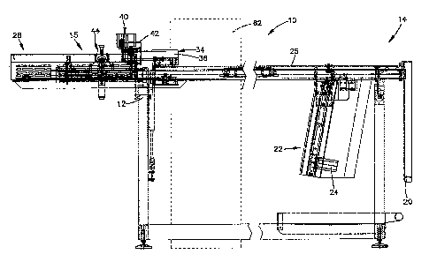
Referring now to the drawings and to Figures 1 through 4 in particular, a
packaging
machine is shown generally at 10. The machine 10 includes a supporting frame
12 upon which
load and closure sections 14,15 are mounted. A web supply platform 16 is
provided at the back
of the machine. The platform 16 is located to the right, as viewed in Figure
1, under an entrance
end 18 of the load section.
3
CA 02773121 2012-03-27
When the machine is in use a supply in the form of a web or chain of side
connect bags is
positioned on the platform. The web is described fully in the SP Patent. The
web is fed around
web guides 20 to the entrance end 18 of the load section 14. The load section
is as described in
the referenced SP Patent with the exception of a redesigned burster 22 which
now is driven by a
stepper motor 24. Operation of the load section is also as described in the S
P Patent while
transport of the web through the load section is accomplished with belts as
described and
claimed in the Load Belt Patents.
One of the outstanding features of the machine 10 is the provision of an
elongate
cylindrical pivot tube 25 which is the, backbone, of the machine. The tube 25
is positioned near
the top and to the rear of the frame 12. The tube 25 extends the full length
of the machine from
the entrance end 18 to an exit end 26. The load and closure sections are
rotatably mounted on
the tube 25. The sections are moveable between generally horizontal operating
positions as
viewed in Figures 1-3 and generally vertical elevated positions as seen in
Figure 4. The elevated
positions are provided to facilitate cleaning and service.
A shock absorber 27 cushions movement between the operating and cleaning
positions.
An adjustable bolt and lock nut 28 act against a stop 30 to accurately
position the sections in
their operating positions, Figure 3. When the sections are in their operating
positions, the shock
absorber is in an extended condition as shown in phantom in Figure 3. When the
sections are in
their cleaning position the shock absorber is fully contracted and vertically
aligned with frame
end post 32, as seen in Figure 4.
When the sections are in the elevated or upright position of Figure 4, the
center of gravity
has gone over center. That is the center of gravity is a) to the left, as seen
in Figure 3, of an
4
CA 02773121 2012-03-27
imaginary plane extending vertically and bisecting vertical posts 32 of the
frame 12 when the
sections are in their operating positions and b) to the right, as seen in
Figure 4, of the imaginary
plane when in their upright positions. Since the center of gravity has passed
over center, the
sections will remain in the upright positions until a force is applied to
rotate the sections about
the axis of the pivot tube to bring the center of gravity to the front (the
left as seen in Figure 3) of
the machine and maintain the sections in the operating positions.
A drive 34 is operable to drive the workpiece feed belts of both the loading
and the
closure sections. Driving force is supplied by a motor 36. The drive also
causes an annular knife
blade 38 to rotate and sever workpiece web lips which support a plastic web as
it is transported
through the loading section, Figure 5. Trimmed scrap is pulled from the
machine by a scrap
puller 40, Figure 2. The puller 40 is driven by the motor 36 via a belt 42.
The trimmed web is fed through the closure section by belts made in accordance
with the
teachings of the Sealer Belt Patent and sealing is effected with sealer
mechanism as described in
the Sealer Belt Patent modified to utilize a new and novel heat source
subassembly 44. Indeed,
the principal novelty of the closer section 15 resides in a heat source
subassembly 44 as shown in
Figures 5 through 9 inclusive.
Referring now to Figures 5 - 9, the subassembly includes an elongate heat tube
46. An
elongate resistance heater 48 is positioned eccentrically in the heat tube 46.
An air supply
conduit 50 is connected to the heat tube to provide a flow of air through a
conduit 51 to and over
the heater 48 to heat the flowing air. The heated air exits through an
elongated opening 52 in the
heat tube 46. The heat tube, when in use, is positioned such that the opening
52 is immediately
CA 02773121 2012-03-27
above a small workpiece space between heater belts 54. The heater belts grip
work pieces (bag
tops) between them and feed the work pieces longitudinally of the opening 52
for sealing.
The provision of a single elongate heating element 48 provides one of the
advantages of
the present machine over the machine of the S P Patent. More specifically the
single heating
element contrasts with the prior machine which used a series of relatively
small resistance
heaters. While the series of heaters simplified the machines design in certain
respects and
reduced repair costs when an element failed, the prior system produced
problems. For example a
heat sensor was provided to sense heater failure. Early stages of failure of
one of the elements
remote from the sensor would not be detected and faulty seals would result.
As is best seen in Figures 7-9, the subassembly 44 includes a handle 56 to
facilitate
removal of the subassembly from and return to the closure section. The
subassembly 44 includes
spaced side mounting plates 58. The mounting plates frictionally engage spaced
side locators of
the closure section to position the subassembly on the closure section. When
the machine is to
be cleaned, an operator grasps the handle 56 and moves the subassembly 44 from
the mounted
position of Figure 7 through the partially removed position of Figure 8 to the
removed condition
of Figure 9. The subassembly is removed by simply lifting the handle upwardly
to remove the
subassembly as a locating rod 60 pivots about a pivot rod 61. The subassembly
is then placed in
a water proof cabinet 62 shown in dotted lines in Figures 1 and 2. The cabinet
62 is constructed
and positioned such that the loading and closure sections 14,15 can be moved
freely from their
operating positions to the cleaning positions and return.
When the subassembly is to be mounted on the closure section, a pointed free
end of the
locating rod is inserted into a mating hole of the subassembly to achieve
location transversely of
6
CA 02773121 2012-03-27
the path of workpiece travel through the closure section. The locating rod
then pivots about the
pivot rod 61 to guide the subassembly into its mounted use position on the
closure section.
When the sections are to be moved from their operating positions to their
cleaning
positions, the sections will be cleared of any plastic web used in packaging
and the subassembly
44 is removed. It is then necessary to rotate the loading section first.
Returning now to Figures
1 through 6 and to Figures 5 and 6 in particular it will be seen that the
reason why the loading
section must be rotated first is, the drive 34, apart from a closure part 64,
is carried by and forms
a part of the loading section 14. As is best understood by reference to Figure
6, the closure part
64 is disconnected from the remainder of the drive 34 when the loading section
is rotated from
its operating to its cleaning position. Upon return to the operating
positions, the closure section
should be returned first.
On subsequent return of the loading section to its operating position a
locating pin 66 in
the closure part extends into an alignment bore 68 in the drive to bring the
drive into appropriate
alignment with the closure part. Once the motor 36 is energized the drive will
rotate until a drive
pin 70 engages a driven pin 72 in the closure part. Once the pins 70,72 are in
engagement the
sealer belts will be driven to feed loaded bags through the closure section.
Any delay between
energizing the motor 36 and driving of the sealer belts is not a problem
because a web of bags
must first be fed through the previously emptied loading section.
Another feature of the invention resides in the provision of a safety air
cylinder 74, best
seen in Figures 7-9. The cylinder is of the type in which a cylinder rod 75 is
spring biased
outwardly such that in a de-energized condition of the cylinder the rod
projects outwardly as far
as the cylinder's construction will permit. When the machine is in operation
the air under
7
CA 02773121 2012-03-27
pressure is supplied to the cylinder and the rod is retracted. Upon a
malfunction of the machine
the cylinder is de-energized and the internal spring drives the piston 75
upwardly. The piston in
turn will engage and elevate the subassembly 44 to space the heat source from
workpieces
between the belts 54.
Although the invention has been described in its preferred form with a certain
degree of
particularity, it is understood that the present disclosure of the preferred
form has been made
only by way of example and that numerous changes in the details of
construction, operation and
the combination and arrangement of parts may be resorted to without departing
from the spirit
and the scope of the invention as hereinafter claimed.
8