Note: Descriptions are shown in the official language in which they were submitted.
CA 02773204 2012-03-05
WO 2011/036438 PCT/GB2010/001769
- 1 -
WELLBORE SERVICING FLUID COMPOSITIONS AND USE THEREOF
FIELD
[0001] This disclosure relates to fluid compositions for servicing a
wellbore. More
specifically, this disclosure relates to wellbore servicing fluid compositions
comprising
polyuronides and their applications.
BACKGROUND
[0002] A natural resource such as oil or gas residing in a subterranean
formation can be
recovered by drilling a well into the formation. The subterranean formation is
usually isolated
from other formations using a technique known as cementing. In particular, a
wellbore is
typically drilled down to the subterranean formation while circulating a
drilling fluid through
the wellbore. After the drilling is terminated, a string of pipe, e.g.,
casing, is run in the
wellbore. Primary cementing is then usually performed whereby a cement slurry
is pumped
down through the string of pipe and into the annulus between the string of
pipe and the walls of
the wellbore to allow the cement slurry to set into an impermeable cement
column and thereby
seal the annulus. Subsequent secondary cementing operations, i.e., any
cementing operation
after the primary cementing operation, may also be performed.
[0003] One example of a secondary cementing operation is squeeze cementing
whereby a
cement slurry is forced under pressure to areas of lost integrity in the
annulus to seal off those
areas. Squeeze cementing is a remedial operation used to accomplish different
objectives. For
example squeeze cementing may be carried out in order to isolate a producing
zone from zones
which produce unwanted fluids; to seal of thief zones or loss circulation
zones; to seal off
perforations in zones which have been depleted; to fix corroded casing leaks;
to prevent fluid
migration in abandoned zones and wells; and/or to correct defects resulting
from primary
cementing jobs such as microannuli formation or the presence of flow channels.
The latter four
CA 02773204 2012-03-05
WO 2011/036438 PCT/GB2010/001769
- 2 -
situations are typically encountered in zones which have casing and cement
behind the casing.
Squeeze cementing may be carried out in order to mitigate or correct for
materials lost due to
the presence of perforations that extend through the casing and cement, or to
prevent the flow of
unwanted fluids such as water into the well bore subsequent to depletion of
the oil in the
perforated and fractured zone. Casing leaks due to holes caused by corrosion
may also allow
unwanted formation fluids to be co-produced with the desired fluid, or allow
for interzonal fluid
communication. Additional adverse conditions that may be ameliorated by
squeeze cementing
include for example sustained casing pressure build up. Sustained casing
pressure build up at
the well head in producing or abandoned wells may be attributable to a number
of factors such
as
fluid migration behind a casing through channels in cement column, or the
presence of
microannuli between the casing and cement, or between the cement and the
formation.
Sustained casing pressure build up can pose a number of hazards. Further, such
casing pressure
build ups can be economically disadvantageous as governmental agencies require
the pressure
build up not to exceed beyond some set values in abandoned wells. In producing
wells, the
sustained casing pressure build up may lead to casing and shoe failures. In
injection and
disposal wells, the presence of alternate flow paths in cased and cemented
zones may lead to
loss of injection pressures and fluid flow into undesired locations.
[0004]
Alternate solutions to squeeze cementing include procedures to seal and plug
the
undesired fluid flow paths by injecting gelling fluids, pressure activated
fluids and by
mechanical isolations. All of these procedures including squeeze cementing are
complex,
laborious and frequently require multiple treatments to fix the problems. For
example, the use
of gelled fluids requires repeated experimentation to optimize the gel time
which is dependent
on a number of factors such as downhole temperatures and the ratio of
components. Thus, there
CA 02773204 2012-03-05
WO 2011/036438 PCT/GB2010/001769
- 3 -
is a need for compositions which are simpler to use and formulate that can
ameliorate the
aforementioned adverse conditions.
[0005] Additionally, oil or gas residing in the subterranean formation may
be recovered by
driving the fluid into the well using, for example, a pressure gradient that
exists between the
formation and the wellbore, the force of gravity, or displacement of the fluid
using a pump or
the force of another fluid injected into the well or an adjacent well. The
production of the fluid
in the formation may be increased by hydraulically fracturing the formation.
That is, a viscous
fracturing fluid may be pumped down the casing to the formation at a rate and
a pressure
sufficient to form fractures that extend into the formation, providing
additional pathways
through which the oil or gas can flow to the well. Unfortunately, water rather
than oil or gas
may eventually be produced by the formation through the fractures therein, and
such fluids may
enter the wellbore through perforations in the production zone, or through
high permeability
channels in the case of a open hole production zone. To provide for the
production of more oil
or gas, a fracturing fluid may again be pumped into the formation to form
additional fractures
therein. However, the previously used fractures and associated fluid pathways
first must be
plugged to prevent the loss of the fracturing fluid into the formation via
those fractures.
[0006] In addition to the fracturing fluid, other fluids used in servicing
a wellbore may also
be lost to the subterranean formation while circulating the fluids in the
wellbore. For example,
a drilling fluid may be lost to the formation, resulting in the circulation of
the fluid in the
wellbore being too low to allow for further drilling. Additionally, wellbore
fluids used in
injection wells to enhance hydrocarbon recovery or fluids designated for
disposal may also be
lost to the subterranean formation. Also, a secondary cement/sealant
composition may be lost
to the formation as it is being placed in the wellbore, thereby rendering the
secondary operation
ineffective in maintaining isolation of the formation.
CA 02773204 2012-03-05
WO 2011/036438 PCT/GB2010/001769
- 4 -
[0007] In particular, the fluids may enter the subterranean formation via
depleted zones,
zones of relatively low pressure, lost circulation zones having naturally
occurring fractures,
weak zones having fracture gradients exceeded by the hydrostatic pressure of
the drilling fluid,
and so forth. As a result, the service provided by such fluids is more
difficult to achieve. In
some cases such fluids may enter natural aquifers that may supply drinking or
agricultural
water.
[0008] Accordingly, an ongoing need exists for compositions and methods of
preventing
the unwanted loss of fluids during wellbore servicing.
SUMMARY
[0009] Disclosed herein is a method of servicing a wellbore in contact with
a subterranean
formation comprising placing a wellbore servicing fluid comprising a
polyuronide polymer
within the wellbore, contacting the wellbore servicing fluid with a divalent
ion source, and
allowing the wellbore servicing fluid to form a gel within the wellbore
wherein the divalent ion
source is located within the wellbore. In an embodiment, the invention further
includes the
steps of shutting the wellbore and allowing the servicing fluid to set into
place for a period of
time, and (c) repeating steps (a) and (b) until the permeability of a
structure within the wellbore
is reduced by about 50%.
[0010] Also disclosed herein is a method of servicing a wellbore in contact
with a
subterranean formation comprising (a) placing a wellbore servicing fluid
comprising a
polyuronide polymer into the wellbore wherein the wellbore servicing fluid
contacts a divalent
ion source, especially a calcium ion source, (b) shutting the wellbore and
allowing the servicing
fluid to set into place for a period of time, and (c) repeating steps (a) and
(b) until the
permeability of a structure within the wellbore is reduced by about 50%.
CA 02773204 2012-03-05
WO 2011/036438 PCT/GB2010/001769
- 5 -
[0011] The foregoing has outlined rather broadly the features and technical
advantages of
the present invention in order that the detailed description of the invention
that follows may be
better understood. Additional features and advantages of the invention will be
described
hereinafter that form the subject of the claims of the invention. It should be
appreciated by
those skilled in the art that the conception and the specific embodiments
disclosed may be
readily utilized as a basis for modifying or designing other structures for
carrying out the same
purposes of the present invention. It should also be realized by those skilled
in the art that such
equivalent constructions do not depart from the scope of the invention as set
forth in the
appended claims.
BRIEF DESCRIPTION OF THE DRAWINGS
[0012] For a detailed description of the preferred embodiments, reference
will now be made
to the accompanying drawings in which:
[0013] Figure 1 is a picture of the samples from Example 1.
[0014] Figure 2 is a picture of the samples from Example 2.
[0015] Figure 3 is a picture of the gel build up on carbonate cores from
Example 3.
[0016] Figure 4 is a picture of a gel build up on carbonate core from
Example 4.
[0017] Figure 5 is a picture of gel build up on shale cores from Example 5.
[0018] Figure 6 is the water leak off graph for samples from Example 6.
[0019] Figure 7 is the gel build up on a cement sample used in Example 7
NOTATION AND NOMENCLATURE
[0020] Certain terms are used throughout the following description and
claims to refer to
particular system components. As one skilled in the art will appreciate,
different companies
may refer to a component by different names. This document does not intend to
distinguish
between components that differ in name but not function.
CA 02773204 2012-03-05
WO 2011/036438 PCT/GB2010/001769
- 6 -
DETAILED DESCRIPTION
[0021] Disclosed herein are wellbore servicing fluid compositions and
methods of using
same. In an embodiment, the wellbore servicing fluid composition comprises a
crosslinkable
polymer system comprising a polyuronide. In another embodiment, the wellbore
servicing fluid
composition consists or consists essentially of a polyuronide. In another
embodiment, the
wellbore servicing fluid composition comprises a crosslinkable polymer system
which consists
or consists essentially of a polyuronide. Such fluid compositions and methods
of making and
using same are described herein in detail.
[0022] In an embodiment, the wellbore servicing fluid (WSF) comprises a
crosslinkable
polymer system comprising a polyuronide. Polyuronides herein refer to a broad
class of
polysaccahrides which are naturally occurring polymers of uronic acid. Uronic
acid is a
monomeric hexose in which the C-6 carbon is oxidized to a carboxylic acid
group. Nonlimiting
examples of polyuronides include alginates, pectinates and tragacanthic acid.
Nonlimiting
examples of uronic acids include galacturonic acid, glucuronic acid, guluronic
acid, and
mannuronic acid. In an embodiment, the wellbore servicing fluid composition
comprises a
polyuronide with a molecular weight (MW) of from about 2000 Daltons to about
1,000,000
Daltons, alternatively from about 200,000 Daltons to about 500,000 Daltons,
alternatively from
about 60,000 Daltons to about 130,000 Daltons.
[0023] In one embodiment the WSF comprises a polyuronide that is a
derivative of alginic
acid, alternatively an alginate, alternatively an alkali or alkaline earth
metal salt of alginic acid.
In an embodiment, the polyuronide is an alginate polymer. In an embodiment the
alginate
polymer comprises an alginate salt. Nonlimiting examples of alginate salts
suitable for use in
this disclosure include potassium alginate, magnesium alginate, calcium
alginate and
CA 02773204 2012-03-05
WO 2011/036438 PCT/GB2010/001769
- 7 -
triethanolammonium alginate. Alternately, the alginate can be used in the acid
form, in
combination with pH adjusting buffers.
10024] Alginate polymers are typically isolated from kelp or sea weed and
contain
monomeric units of alpha-L-guluronic acid (G unit) and beta-D mannuronic acid
(M unit) and
may be organized as: (1) homopolymeric M blocks (polymarmuronate an example of
which is
depicted in Structure 1A); (2) homopolymeric G blocks (polyguluronate an
example of which is
depicted in Structure 1B); or (3) heteropolymeric G-M blocks with randomly
arranged GG and
MM block sequences (an example of which is depicted in Structure 1C),
alternating GM
sequences; or any combination thereof
CO2Na CO2Na
I-1 0 HO
HO
0 0 0
HO HO 0
r, 02Na F16,,,
Structure 1A
H H H H
OH
=H Y
-00C H
/4.--.. -OH
i
H ---lx H H H
---"µ H
----S__. H
""--7.--
H OH ----1.--
H OH
H H H H
StructurelB
H H H H C00- COO-
HO 0
N
0 HO
-00C '-' OH HO HO
0
EH HI 111-)µ:-:-F1 HI 001-10
_ OH -00C
_ -
_ =
0 l',.. 1-1 -00C 0 S_OH -00C
-----y- H H OH -----r- OH
H
H H H
Structure 1C
CA 02773204 2013-11-29
- 8 -
[0025] An alginate suitable for use in the present disclosure may comprise
heteropolymeric
GM blocks and have an M:G ratio of from about 2:8 to about 8:2 alternatively
from about 3:7 to
about 7:3, alternatively from about 4:6 to about 6:4. In an embodiment, the
alginate is a high
GG block alginate containing equal to or greater than about 25% GG blocks,
alternatively equal
to or greater than about 40% GG blocks, alternatively equal to or greater than
about 50% GG
blocks. Without wishing to be limited by theory, it is believed that GG blocks
provide gelling
ability to the polymer molecule upon interaction with Group II metal ions,
whereas GM blocks
and MM-blocks provide flexibility to the molecule.
[0026] In an embodiment, the alginate polymer may be altered to meet some
user and/or
process desired need. For example, the alginate polymer may be altered
enzymatically using
epimerases. In an embodiment, the alginate polymer is chemically modified by
esterification of
native carboxylate groups with alcohols such as propylene glycol, ethylene
glycol, and
methanol. Methods and compositions for esterification of alginate polymers are
known to one
of ordinary skill in the art with the benefits of this disclosure.
[0027] Examples of commercially available alginates suitable for use in
this disclosure
PM 1M
include without limitation KELCOLOID LVF, and KELCOLOID HVF which are
alginates
having a portion of the carboxylate groups esterified with propylene glycol
and MANUGEIim
GHB which is a sodium alginate each of which is available from ISP Polymers
Inc. In an
embodiment, the WSF comprises an alginate polymer of the type described herein
with a
molecular weight (MW) of from about 14,000 Daltons to about 1,000,000 Daltons
alternatively
from about 100,000 Daltons to about 700,000 Daltons, alternatively from about
200,000
Daltons to about 500,000 Daltons.
[0028] In an embodiment, the WSF comprises a polyuronide comprising a
pectinate
polymer. Chemically, pectin is a straight chain of a-D-galacturonic acid
molecules linked by
CA 02773204 2012-03-05
WO 2011/036438 PCT/GB2010/001769
- 9 -1,4-glycosidic linkages which are all di-equatorial due to the Cl
conformation. The structure of
D-galacturonic acid is shown below (Structure 2).
02H
=H =
=H
OH
OH
Structure 2
[0029] The carboxylate groups in native pectinates are present
predominantly as methyl
esters with varying degrees of methylation. Pectinate polymers, depending on
the degree of
methylation may either form clear solutions (high methylation) or turbid
suspensions with low
viscosity (low methylation). Herein a high degree of methylation refers to
from about 50% to
about 80% of the C6-COOH present as the methyl ester, while a low degree of
methylation
refers to methylation of less than about 50% of the carboxylic acid groups
present. The
remaining non-methylated carboxylic acid groups may be present as free -COOH
groups, or as
sodium, potassium, calcium or ammonium groups. In an embodiment, a portion of
the methyl
ester groups may be reacted with ammonia to form an amide group and as a
result of this
reaction the resulting polymer may contain, amide groups, methyl ester groups
and carboxylic
acid groups or the salt form of the carboxylic acid groups. In an embodiment,
a pectinate
suitable for use in this disclosure has a degree of methylation of from about
20% to about 50%,
alternatively from about 25% to about 48%, alternatively from about 30% to
about 40%. In an
embodiment, pectinates suitable for the present disclosure include any
combination of C6-
amide groups and C6-methyl ester groups, provided that the sum of amide and
ester groups are
within the above disclosed range.
CA 02773204 2013-11-29
- 10 -
[00301 In an
embodiment, the WSF comprises a metal salt of a pectinate polymer. In an
embodiment, the WSF comprises an alkali metal salt of a pectinate polymer,
alternatively a
sodium or potassium salt of a pectinate polymer. In an embodiment, the WSF
comprises
sodium pectinate. The sodium salts of pectinates may be highly water soluble,
partially water
soluble, or water dispersible depending on a variety of factors such as the
degree of
methylation, the type of other solids present and pH.
[0031]
Examples of commercially available pectinates suitable for use in this
disclosure
TM TM
include without limitation GENU X-914 (low methylation) and GENU PECTIN
(Citrus)
USP/100 (high methylation) each of which is available from CP Kelco Inc.
Pectinate polymers
are also used in preparation of fruit jams and jellies. A food grade pectin,
which also contains
TM
citric acid and glucose, is available in stores under the trade name SURE
JELL.
[0032] In an
embodiment, the WSF comprises a pectinate polymer with a MW of from
about 30,000 Daltons to about 1,000,000 Daltons, alternatively from about
70,000 Daltons to
about 700,000 Daltons, alternatively from about 60,000 Daltons to about
250,000 Daltons.
[0033] In an
embodiment, the WSF comprises a polyuronide polymer which is present in
the WSF in an amount of from about 0.05 wt.% to about 8 wt.%, alternatively
from about 0.1
wt.% to about 6 wt.%, alternatively from about 0.2 wt.% to about 3 wt.% by
weight of WSF.
In an embodiment, the WSF comprises an alginate polymer which is present in
the WSF in an
amount of from about 0.05wt.% to about 6 wt.%, alternatively from about 0.1
wt.% to about 4
wt.%, alternatively from about 0.2 wt.% to about 2 wt.% by weight of WSF. In
an
embodiment, the WSF comprises a pectinate polymer which is present in the WSF
in an amount
of from about 0.1 wt.% to about 8 wt.%, alternatively from about 0.5 wt.% to
about 6 wt.%,
alternatively from about 1.0 wt.% to about 4 wt.%.
CA 02773204 2012-03-05
WO 2011/036438 PCT/GB2010/001769
-11-
100341 In an embodiment, a WSF comprising a polyuronide of the type
described herein
(e.g. alginate, pectinate) forms a gel when contacted with a divalent ion
source. As used herein,
a gel is defined as a crosslinked polymer network swollen in a liquid medium.
The divalent ion
may comprise any divalent ion able to crosslink polyuronides of the type
disclosed herein to
form a gel. In an embodiment, the divalent ion comprises Group II metal ions.
Without
wishing to be limited by theory, the propensity of polyuronides to form a gel
when contacted
with a Group II metal ion may be ordered as follows: Mg2+<<Ca2 ¨Ba2+¨Sr2+.
[0035] In an embodiment, the WSF comprising a polyuronide contacts a
divalent ion source
when placed in the wellbore. Further, it is contemplated that prior to
introduction to the
wellbore, the WSF is not contacted with a divalent ion source and/or a
divalent ion. In an
embodiment, the divalent ion source is a source of divalent Group II metal
ions. Hereinafter for
simplicity the disclosure will refer to the Group II metal ions and as will be
understood by one
of ordinary skill in the art the Group II metal ions are in a divalent
oxidation state. Nonlimiting
examples of Group II metal ions in situ sources include carbonate rock, shale
rock and fractured
or debonded cement surfaces. For example, the Group II metal ion source may be
the face of
the subterranean formation or a cement sheath disposed within the formation.
As such the gels
form in-situ after placement of the WSF comprising a polyuronide into the
subterranean
formation.
[0036] In an embodiment the Group II metal ions are present proximate to
the surface of the
source (e.g. formation or wellbore) or may readily partition or diffuse into
the WSF upon
contact. In cases where the formation or well bore surfaces do not contain
sufficient quantities
of Group II metal ions to form gels with polyuronides, Group II metal ions may
be provided in a
treatment fluid prior to introduction of the WSF comprising a polyuronide into
the wellbore or
the formation. In such an embodiment, the treatment fluid may be introduced to
the wellbore or
CA 02773204 2012-03-05
WO 2011/036438 PCT/GB2010/001769
- 12 -
formation such that the formation or wellbore surfaces may be coated or made
to contain the
Group IT metal ion in the outside layers of the surface, for example as part
of a filtercake. Such
treatment fluids may be solutions of soluble Group II metal ion salts, or
suspensions of Group II
metal ion water-insoluble salts such as calcium carbonate, or sparingly
soluble salts such as
calcium sulfate-hydrate or barium sulfate.
[0037] In an embodiment, the Group II metal ion comprises calcium. In other
embodiments, the Group II metal ion comprises barium. Hereinafter the
disclosure will discuss
the use of calcium ions as the Group II metal ion; however other Group II
metal ions as
discussed previously herein are also contemplated.
100381 In an embodiment, the WSF comprising a polyuronide is contacted with
calcium
ions that may be present naturally in the subterranean formation that contains
the wellbore.
Examples of subterranean formations containing calcium ions include calcium
carbonate
formations such as dolomite and calcite, shale rock and cementicious material
that binds sand
grains in a sandstone formation. In a completed wellbore that has been cased
and cemented, the
source of the calcium ion may be the cement column behind the casing
comprising Portland
cement, calcium alurninate cement, calcium oxide cement, Class C flyash
cements and/or
cement kiln dust containing cements. In an embodiment, the WSF comprising
polyuronides is
contacted with calcium ions that are introduced to the wellbore or formation.
Calcium ions may
be introduced into the formation as a pretreatment fluid such as a soluble
calcium salt solution
or a calcium chloride solution. The pretreatment fluid may contact the
surfaces of the formation
and allow for the deposition of calcium onto the surfaces prior to contacting
the treated surfaces
with a WSF comprising polyuronide of the type described herein. Without
wishing to be
limited by theory, is believed that the Group II metal ions (e.g., calcium)
from the source (e.g.,
cement sheath) diffuse to the binding sites in polyuronides and form gels at
rates defined by a
CA 02773204 2012-03-05
WO 2011/036438 PCT/GB2010/001769
- 13 -
variety of factors such as diffusion rates, solubility and temperature. In an
embodiment, a
method of servicing a wellbore comprises contacting a WSF comprising a
polyuronide of the
type described herein and a Group II metal ion (e.g., calcium) and
subsequently employing a
shut-in time of appropriate duration.
[0039] Without wishing to be limited by theory, the calcium ions may
function to crosslink
the carboxylate groups of the polyuronide by forming what are known as "egg-
crate" structures
as shown below.
0
-04
0
HO 4DII
C
-# O"
e. "
0 10
¨k,49.1
seeirr-9
1/4_1 -0
Hd
14\
\01
Structure 3A Structure 3B
[0040] Structure 3A is a representation of the egg-crate structure formed
by contacting
calcium with an alginate to form calcium alginate. In structure 3A the circles
represent Calf
ions; Structure 3B is an expanded view of a portion 10 of the calcium alginate
structure depicted
in Structure 3A.
[0041] The gels formed when a WSF fluid comprising a polyuronide is
contacted with a
Group II metal ion (both of the type described herein) range from rigid to
elastic gels. Herein a
rigid gel qualitatively refers to gels with dimensional stability that is the
gel strength will
support the retention of the shape and is non-flowable, while an elastic gel
qualitatively refers to
CA 02773204 2012-03-05
WO 2011/036438 PCT/GB2010/001769
- 14 -
a gel that is elastically deformable and may be flowable. It is to be
understood that the gels
formed according to the compositions and methods disclosed herein may
initially be flowable,
and elastic and in some instances will transition to form rigid and non-
flowable gels. Such a
transition may be the result of continued contact of the polyuronide with the
Group II metal ion
resulting in the continued incorporation of the Group II metal ion into the
gel structure. As will
be understood by one of ordinary skill in the art the type of gel formed will
depend on a variety
of factors such as the nature (e.g., molecular composition such as G/M ratio,
block structure,
degree of methylation and the like) and amount of polymeric materials and
metal ions, reaction
temperature, pH, ionic strength and strength of the gel structure. Further,
the strength of the gel
formed will depend on a variety of factors such as the concentration of the
reactants, ionic
strength, and pH of the solution.
[0042] The gels formed according to this disclosure are examples of ionic
gels, also
referred to as ionotropic gels. Ionotropic gels are formed when
polyelectrolytes, for example an
anionic polymer such as alginate or pectinates, are contacted with polyvalent
metal ion of
opposite charge. These gels are physical gels, which is to say that the three
dimensional gel
network is formed by ionic associations between opposite charges and not due
to covalent
bonds.
[00431 In an embodiment, the WSF comprises an alginate of the type
described herein.
Upon contact with a Group II metal ion source, of the type described herein,
the WSF forms a
gel with the Group II metal ions that are available from the ion source (e.g.,
surface metal ions)
as described previously herein. In such an embodiment, the gel time may be
adjusted to meet
some user and/or process-desired need by chemical modification of the alginate
polymer, such
as by esterification. Gel time herein refers to the period of time from
initial contact of the
CA 02773204 2012-03-05
WO 2011/036438 PCT/GB2010/001769
- 15 -
components to the point when a gel is formed. Esterification of the alginate
polymers to extend
gel times has been previously described herein.
[0044] In an embodiment, the degree of esterification of the alginate
polymers is adjusted
so as to change the kinetics of the interaction between the alginates and the
Group II metal ion.
For example, increasing the degree of esterification of the alginate may
increase the gel time
when the WSF contacts a Group II metal ion. In an alternative embodiment, the
degree of
esterification of the alginates may be decreased so as to decrease the gel
time of the WSF
comprising alginates. The degree of esterification of the alginate may be
adjusted prior to
inclusion of the alginate in the WSF using the methodologies previously
disclosed herein.
[0045] In an alternative embodiment, the WSF may contain one or more in-
situ acid
generating materials. Such in-situ acid-generating materials may accelerate
the rate of gelation
of the WSF comprising alginates by hydrolysis of the ester groups present on
the alginate.
Hydrolysis of the ester groups would liberate free acid groups which in turn
could further
reduce the esterification of the alginate. Alternatively or in addition to
hydrolysis of the
alginate ester groups, in situ acid-generating materials may increase the
availability of the
divalent ions by aiding in dissolution of the formation or wellbore materials,
thereby facilitating
the release of the Group II metal ions. Nonlimiting examples of in-situ acid
generating
materials suitable for use in this disclosure include gluconolactone, citric
acid, and polylactic
acid. In an embodiment, the in situ acid generating material is present in the
WSF in an amount
of from about 0.1 wt.% to about 10 wt.%, alternatively from about 0.5 wt.% to
about 8 wt.%,
alternatively from about 1 wt.% to about 5 wt.% by weight of the polyuronide.
[0046] In an embodiment, a WSF comprising a pectinate, when contacted with
a Group II
metal ion source (both of the type described herein), forms a gel as described
previously herein.
As will be understood by one of ordinary skill in the art, depending on a
variety of factors,
CA 02773204 2012-03-05
WO 2011/036438 PCT/GB2010/001769
- 16 -
pectinates may form turbid solutions. However, the turbidity of the pectinate
in the WSF does
not affect gelation of these solutions or suspensions in the presence of Group
II metal ions of
the type described herein.
[0047] In some embodiments, pectinates in the WSF comprise carboxylate
groups which
are present predominantly as methyl esters. The degree of methylation of the
pectinate may be
a determinant in the reactivity of the pectinate with the Group II metal ions
and the rate of gel
formation. Alternatively or in addition to, pectinates in the WSF may comprise
an amidated
pectinate. Herein an amidated pectinate refers to a pectinate that has at
least a portion of the
carboxylate groups converted to amide groups by reaction with ammonia. In an
embodiment,
the degree of methylation of the pectinate may be varied so as to adjust the
gelation time when
the WSF comprising a pectinate is contacted with one or more Group II metal
ions. The gel
time may be adjusted so as to meet some user and/or process-desired need. In
an embodiment,
the WSF comprises a low methylation pectin and/or an amidated low methylation
pectin.
Without wishing to be limited by theory, such low methylation and/or amidated
low
methylation pectins may provide increased flexibility in the adjustment of gel
time when
compared to high methylation and amidated high methylation pectins.
[0048] In an embodiment, the WSF may further comprise one or more additives
or
modifying agents as deemed necessary to impart the desired physical
properties. Such additives
may include but are in no way limited to fluid absorbing materials, resins,
aqueous
superabsorbers, viscosifying agents, suspending agents, dispersing agents,
salts, accelerants,
surfactants, retardants, defoamers, settling prevention agents, weighting
materials, dispersants,
vitrified shale, formation conditioning agents, or combinations thereof These
additives may be
included singularly or in combination. Methods for introducing these additives
and their
CA 02773204 2012-03-05
WO 2011/036438 PCT/GB2010/001769
- 17 -
effective amounts, as well as methods of incorporating these additives into
the WSF are known
to those of ordinary skill in the art.
[0049] In an embodiment, the WSF may contain one or more sequestering
agents. Such
sequestering agents, also termed chelating agents, may function to
preferentially contact and
sequester or chelate ions that may impede or detrimentally impact the
interaction of a Group II
metal ion with a polyuronide. For example, the sequestering agent may
preferentially sequester
iron (e.g., Fe2+) or lead (e.g., Pb2+) present in the formation. Sequestering
agents suitable for
use in this disclosure are known to one of ordinary skill in the art with the
aid of this disclosure.
Nonlimiting examples of such sequestering agents include
ethylenediaminetetracetic acid,
diethylenetriaminepentaacetic acid, N,N-bis(carboxymethyl)glycine, citric
acid, and acetic acid.
[0050] In some embodiments, the WSF comprising polyuronide polymers
comprises
crosslinking agents. Any crosslinking agent able to aid in the formation of a
gel having
properties as described herein and compatible with the other components of the
composition
may be employed.
[0051] The gel time of a WSF comprising polyuronide polymers in the
presence of Group
II metal ions of the type described herein will depend on a number of factors
such as the
composition and concentration of the polymer, the composition, concentration
and diffusion
rates from the sources of the Group II metal ions, and the Group II metal ion
source. In an
embodiment, the gel time of a WSF comprising polyuronides when contacted with
a Group II
metal ion source at room temperature ranges from about 5 hrs to about 76 hrs,
alternatively
from about 10 hrs to about 48 hrs, alternatively from about 18 hrs to about 30
hrs. It should be
understood that gel time in the formation of ionic or ionotropic gels depends
on the
measurement method of gel strength, because the polymer solution will keep
forming the gel
from the surface of the metal ion source outward as long as either the
ungelled polymer solution
CA 02773204 2012-03-05
WO 2011/036438 PCT/GB2010/001769
- 18 -
is available and/or the divalent metal ions are available. In wellbore
treatment or formation
injection applications, the available space filled with the polymer solution
will gradually and
ultimately be filled with gelled polymer by gel formation extending from the
interface of
polymer solution and metal source outward. To aid in competent gel formation
to accomplish
desired goal, a shut-in time of appropriate duration after pumping the WSF
comprising
polyuronides is contemplated.
[0052] The gels formed when a WSF comprising a polyuronide is contacted
with a Group II
metal ion source (both of the type described herein) may be thermally stable.
Herein a
thermally stable gel refers to a gel that resists water expulsion accompanied
by gel volume
reduction, or disintegration of the gel to a thin solution of viscosity less
than that of a gel at
elevated temperatures. For example, the gel formed when a WSF comprising a
polyronide is
contacted with a Group II metal ion source may be stable at a temperature
ranging from about
50 F to about 300 F; alternatively at a temperature ranging from about 75 F
to about 200 F;
alternatively at a temperature ranging from about 100 F to about 180 F for
periods equal to or
greater than about 1 week.
100531 As used herein, a "servicing fluid" refers to a fluid used to drill,
complete, work
over, fracture, repair, or in any way prepare a wellbore for the recovery of
materials residing in
a subterranean formation penetrated by the wellbore. Examples of servicing
fluids include, but
are not limited to, drilling fluids or muds, spacer fluids, fracturing fluids,
completion fluids,
remedial fluids, and treatment pills all of which are well known in the art.
It is to be understood
that the WSF should not contain components which interfere with gelation of
polyuronide or
prematurely gel polyuronide prior to its intended use. The servicing fluid is
for use in a
wellbore that penetrates a subterranean formation. It is to be understood that
"subterranean
formation" encompasses both areas below exposed earth and areas below earth
covered by
CA 02773204 2012-03-05
WO 2011/036438 PCT/GB2010/001769
- 19 -
water such as ocean or fresh water. Hereinafter, a WSF may comprise any of the
polyuronides
disclosed previously herein and which are collectively referred to hereinafter
as Group II metal
ion crosslinkable polymer systems (G2-CPS). In some embodiments, the G2-CPS
excludes a
gel modifier wherein the gel modifier comprises borates, polyvinyl alcohols,
polycarboxylic
acids, polyacrylamides, or mixtures thereof. Alternatively, the G2-CPS
excludes a gel modifier
wherein the gel modifier is selected from the group consisting of borates,
polyvinyl alcohols,
polycarboxylic acids, polyacrylamides, and mixtures thereof.
[0054] In an embodiment, the WSF comprises a drilling fluid. That is the G2-
CPS is
combined with one or more components of a drilling fluid. The resulting
composition (i.e.,
drilling fluid + G2-CPS) may function to reduce fluid loss to the formation
permeability.
Drilling fluids are generally viscous, heavy fluids designed to perform a
variety of functions
during well drilling, including (1) preventing formation fluids from entering
into the wellbore
and causing a blow out by exerting sufficient pressure against the formations
being drilled; (2)
keeping the drilling bit cool and clean during drilling; (3) bringing out the
cuttings generated by
the bit; (4) keeping the cuttings in suspension; and (5) minimizing reservoir
damage and
limiting corrosion. Drilling fluids may be water-based or oil-based. In an
embodiment, the
WSF comprises any drilling fluid compatible with the needs of the process. For
example,
drilling fluids that substantially alter the gel time of the polyuronide may
be avoided. In an
embodiment, a conventional drilling fluid containing insoluble calcium salts
as bridging particles
to improve the fluid loss characteristics of filter cake deposited on the well
bore walls, is used to
drill the well. A second treatment fluid comprising a G2-CPS and an additive
(e.g., an acid) that
will dissolve small amounts the insoluble calcium salt is circulated in the
wellbore.
Alternatively, the second treatment fluid comprises a G2-CPS is in an acid
form. In such
embodiments, the additive or acid form of the G2-CPS may function to dissolve
the insoluble
CA 02773204 2012-03-05
WO 2011/036438 PCT/GB2010/001769
- 20 -
calcium salt thus providing Group II metal ions (e.g., calcium) to the
filtercake formed on the
surface of the wellbore. Consequently, the G2-CPS when contacted with the
Group II metal ion
forms a gel that extends outward from the surface of the filtercake thereby
improving the fluid
loss control property of the filtercake. Similarly, a sequence of treatments
may be designed and
used to control loss circulation of drilling fluids into thief zones or
fractures. In an embodiment,
a method of improving the fluid loss control property of a filtercake
comprises placing in the
wellbore a drilling fluid comprising a graded calcium carbonate of suitable
particle size. The
method further comprises introducing a material which can dissolve the graded
calcium
carbonate, such as for example citric acid to form solublized calcium
carbonate. The method
may further comprise contacting the surfaces containing the solubilized
calcium carbonate with a
G2-CPS of the type described herein.
[0055] In an alternative embodiment, a method of improving the fluid loss
control property
of a filtercake comprises placing in the wellbore a drilling fluid comprising
barite (barium
sulfate), which is sparingly soluble in water. The method may further comprise
introducing a
G2-CPS of the type described herein thereby contacting the G2-CPS with one or
more surfaces
of the wellbore that have been pretreated with barite. Barite may provide
effective amounts of
barium ions for gelling the polyuronide solution.
[0056] In an embodiment, the WSF comprising a G2-CPS is substantially
solids-free.
Herein substantially solids free refers to the composition having less than
about 10% particles
by volume of WSF comprising a G2-CPS where the particle size is greater than
about 5
micron.
[0057] In an embodiment, the WSF comprising a G2-CPS is a conformance
control fluid.
Herein conformance control refers to any action taken to improve the water to
oil ratio; that is to
decrease the amount of water while increasing or without significantly
decreasing the amount of
CA 02773204 2012-03-05
WO 2011/036438 PCT/GB2010/001769
- 21 -
oil in the produced fluids. This is conventionally accomplished in watered out
zones by
pumping gelling fluids with optimized gel times in zones which are well
separated from oil
producing zones. An advantage of the methods and compositions of the current
disclosure is
that prior optimization of gel times is not necessary because the gelling
agent is provided by the
formation. In zones which are devoid of significant amounts of Group II metal
ion containing
minerals, the Group II metal ion (e.g., as a calcium salt solution) may be
injected into the
formation as the first treatment fluid, followed by a polyuronide solution. In
some
embodiments, the two treatment fluids are separated by an aqueous spacer
fluid.
[0058] In an embodiment, a WSF comprising a G2-CPS of the type described
herein is
contacted with a Group II metal ion during an enhanced oil recovery operation
(EOR). For
example, to sweep bypassed zones, fluids such as viscosified polymer solutions
or surfactant
solutions may be pumped into a formation via an injector well. However, such
fluids may
bypass oil zones by flowing through high permeability channels that connect an
injector well to
a producer well. In order to increase the sweeping efficiency of an EOR fluid,
WSF comprising
a G2-CPS may be pumped into the injector well first, where it contacts a Group
II metal ion
source and is allowed to form gels in the high permeability channels thereby
sealing such flow
paths. A subsequent injection of an EOR fluid system would then sweep bypassed
oil zones
more effectively.
[0059] In an embodiment, the WSF comprising a G2-CPS is a loss circulation
fluid
composition. The WSF comprising a G2-CPS when placed in a loss circulation
zone that
contains a Group II metal ion source of the type previously described herein
produces a
permanent plug that is rigid, adhesive and of appreciable compressive
strength.
[0060] In embodiments, the WSF comprising a G2-CPS may be introduced to the
wellbore
to prevent the loss of aqueous or non-aqueous drilling fluids into loss
circulation zones such as
CA 02773204 2012-03-05
WO 2011/036438 PCT/GB2010/001769
- 22 -
voids, vugular zones, and natural or induced fractures while drilling. In an
embodiment, the
WSF comprising a G2-CPS is placed into a wellbore as a single stream and
activated by Group
II metal ions (such as calcium ions) contained in a Group II metal ion source
to form a barrier
that substantially seals lost circulation zones. In such an embodiment, the
fluid may be placed
downhole through the drill bit forming a composition that substantially
eliminates the lost
circulation. In an embodiment, the gel plug formation may be enhanced by
placing insoluble
salts of Group II metal ions of suitable size into the lost circulation zone,
followed by contacting
such solids with G2-CPS (e.g., polyuronide solution) containing suitable
amounts of materials
that partially dissolve the insoluble Group II metal ion salt and provides an
amount of the Group
II metal ion effective to form gels when contacted with the G2-CPS.
[0061] In some embodiments, the WSF comprising a G2-CPS may form a non-
flowing,
intact mass inside the lost circulation zone which plugs the zone and inhibits
loss of
subsequently pumped drilling fluid, which allows for further drilling. In an
embodiment, the
well is shut-in for a suitable duration to complete the plugging phenomenon as
may be evident
by circulation of the desired fluid without loss to the formation, or by
increased injection
pressures.
[0062] Many producing and abandoned oil wells develop cracks or flow
pathways due to a
variety of factors such as imposed stresses from cyclic pressure, temperature
changes during the
production phase of the well, and/or debonding of cement column from either
the formation
and/or the casing. The flow paths in the latter case are generally referred to
as microannuli. In
some embodiments, the WSF comprising a G2-CPS is used as a sealing squeeze
fluid that is
effective in sealing off micro-annuli and preventing the flow of unwanted
fluids through the
well.
CA 02773204 2013-11-29
- 23 -
[0063] For example, the WSF comprising a G2-CPS may be introduced to a
wellbore that
has developed one or more microannuli. Introduction of the WSF comprising a G2-
CPS may
involve forcibly injecting under pressure (squeezing) the material into one or
more microannuli
accessible to the user. Introduction of the WSF comprising a G2-CPS is
typically followed by a
shut-in period wherein the fluid is allowed to form a gel. Subsequent forcible
injections of the
WSF comprising a G2-CPS and shut-in periods may be carried out until the
squeeze pressures
reach values that are sufficiently high so as to insure blockage of the
microannuli. In some
embodiments, the WSF comprising a G2-CPS is introduced to an abandoned or
leaking well in
order to mitigate pressure behind the casing or at a wellhead.
[0064] In an embodiment, the WSF comprising a G2-CPS is used for sealing
off holes in a
casing that has been cemented, or to seal perforations through cement in a
zone that is depleted
so that another oil bearing zone can be stimulated by perforation and
fracturing. The procedure
for accomplishing such sealing action is similar to the squeezing procedure
described above.
Various procedures that may be followed to use a sealant composition in a
wellbore are
described in U.S. Patent Nos. 5,346,012 and 5,588,488.
[0065] In an embodiment, a WSF comprising a G2-CPS is used for treating
wellbores
completed in subterranean formations containing Group II metal ions, such as
calcium based
minerals, for example, calcium carbonate formations, dolomite formations and
shale zones. In
some embodiments, the WSF comprising a G2-CPS comprises alginate polymers. In
some
embodiments, the WSF comprising a G2-CPS comprises pectinate polymers.
100661 When a WSF comprising a G2-CPS is injected downhole in subterranean
formations, Group II metal ions (such as calcium ions) that are components on
the mineral
surface of the formations, when coming in contact with the fluid, cause the
fluid to form a gel.
CA 02773204 2012-03-05
WO 2011/036438 PCT/GB2010/001769
-24 -
In some embodiments, the Group II metal ions on the surface of the formation
are depleted by
reaction with WSF comprising a G2-CPS. It is contemplated that in such
embodiments,
additional gel formation may occur when Group II metal ions contained in the
formation diffuse
to the surface and react with the fluid.
[0067] In an embodiment, subterranean well bore surfaces are the sources of
the Group II
metal ion (or contain one or more Group II metal ion as a structural component
of the
formation). In an embodiment, the cement column behind a casing is the source
of Group II
metal ion. In an embodiment, the well bore surface is pretreated with a Group
II metal ion
source prior to contact with the WSF comprising a G2-CPS. In an embodiment,
one or more
Group II metal ion containing particulate solids is incorporated into an
aqueous wellbore
treatment fluid as a bridging agent to control fluid loss characteristics of a
filter cake. In an
embodiment, the Group II metal ion is pre-reacted with the WSF comprising a G2-
CPS (or the
G2-CPS is cross-linked with a Group II metal) and the resulting material is
used in a
dehydrated, particulate form in a non-swelling treatment fluid, and allowed
swell in the
wellbore by contacting with a swelling fluid. In an embodiment, the Group II
metal is calcium.
In an embodiment, the well bore treatment fluid is injected into the
permeability of the
subterranean formation and allowed to contact with Group II metal ion source
in the porosity of
the subterranean formation.
[0068] In some embodiments, the WSF comprising a G2-CPS is a drilling
fluid, a
conformance control fluid, an EOR fluid, a lost circulation fluid or
combinations thereof. In
some embodiments, the WSF comprising a G2-CPS is a squeeze fluid for cemented
zones.
[0069] In an embodiment, the WSF comprising a G2-CPS may reduce the
permeability of a
formation to which it is introduced by greater than about 50%, alternatively
greater than about
75%, alternatively greater than about 99%.
CA 02773204 2012-03-05
WO 2011/036438 PCT/GB2010/001769
- 25 -
EXAMPLES
[0070] The invention having been generally described, the following
examples are given as
particular embodiments of the invention and to demonstrate the practice and
advantages thereof.
It is understood that the examples are given by way of illustration and are
not intended to limit
the specification of the claims in any manner.
EXAMPLE 1
[0071] The ability of a WSF comprising a G2-CPS to form a gel when
contacted with a
multivalent metal ion source was investigated. Three alginate polymers were
tested by
exposing a 0.5% solution of these polymers to a set Portland cement cylinder
in a beaker.
Samples A, B, and C comprised KELCOLOID LVF; MANUGEL GHB; and a sodium
alginate
solution, respectively. KELCOLOID LVF, is an algin polymer commercially
available from
FMC Biopolymer that has been chemically modified by partial esterification of
native
carboxylate groups with propylene glycol to delay interaction with calcium
ions and has a
viscosity of <50 cP, MANUGEL GHB is a low molecular weight sodium alginate
with a
viscosity of <25 cP commercially available from ISP Performance Chemicals. The
sodium
alginate solution is a high molecular weight polymer commercially available
from Aldrich
Chemical Company.
[0072] At room temperature, a gel began to form next to the cement skin
that extended
outward into the solution when the system was allowed to stand quiescently.
[0073] The glass containers containing the cement cylinders and polymer
solutions were
kept in a water bath maintained at 150 F for more than a week. The formed gels
remained
intact ¨ i.e., the gels did not break down and the viscosity did not decrease
substantially. A
picture of the cylinders with formed gels is shown in Figure 1. The cylinders
were held upside
down to more clearly depict the gel formed.
CA 02773204 2012-03-05
WO 2011/036438 PCT/GB2010/001769
- 26 -
EXAMPLE 2
[0074] The ability to form a gel by contacting a pectinate and a divalent
metal ion source
was investigated. A food grade pectin available in stores under the trade name
SURE JELL
was dissolved in deionized water to make 1% and 5% solutions. A set Portland
cement cylinder
(2" in diameter) was placed in each solution arid allowed to stand in a bottle
for a day at room
temperature. The sample in 1% solution had a thin gel layer formed on the
immersed portion of
the cylinder and there were gel chunks in the water. The 5% solution formed a
fairly stiff gel on
the cylinder surface (Figure 2). The proprietary powder of SURE JELL lists
citric acid,
dextrose and fruit pectin as its ingredients. The results demonstrate the
ability of a pectin
polymer to form a gel upon contact with a multivalent metal ion source (i.e.,
Portland cement
cylinder).
EXAMPLE 3
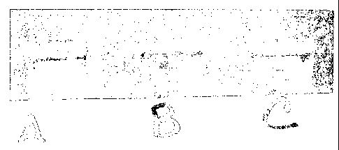
[0075] The ability to form a gel by contacting a polyuronide and a
carbonate source was
investigated. Carbonate cores (Bedford carbonate) were allowed to stand at
room temperature
in 1% solutions of three alginate polymers ¨ partially esterified alginate
(KELCOLOID LVF),
a non-esterified sodium alginate (MANUGEL GHB), and sodium alginate from
Aldrich
Chemical Company. Gels started to form on the immersed portions of the
carbonate cores
within a few hours. Over a longer period of time, the gel grew in mass. For
KELCOLOID
LVF, the entire solution became a gel; whereas in the other two cases, only
the core-exposed
fluid formed a gel.
[0076] The carbonate cores with gelled ends are shown in Figure 3: left
core ¨
KELCOLOID LVF, middle core ¨ MANUGEL GHB, and the right core ¨ Aldrich sodium
alginate.
CA 02773204 2012-03-05
WO 2011/036438 PCT/GB2010/001769
- 27 -
EXAMPLE 4
[0077] Formation of a gel using carbonate core (Bedford carbonate) and
another
commercially available pectinate polymer solution was investigated. The
experiment was
carried out as described in Example 3 using GENU X-914 which is a pectin
polymer
commercially available from ISP Polymers Inc. The core with a gelled end is
shown in Figure
4.
[0078] Pectinate solutions, depending on the degree of methylation may
either form clear
solutions (high demethylation) or turbid suspensions with low viscosity (low
demethylated).
The degree of turbidity does not affect gelation around the core, suggesting
that such
suspensions are suitable for treating fractures.
[0079] The results from Example 3 and Example 4 clearly show that stiff
gels are formed
from alginate and pectinate solution via reactions with calcium ions extracted
(or dissolved)
from the carbonate cores. Furthermore, the pectinate and alginate solutions
have low viscosity
and thus are suitable for matrix injection without using excessive injection
pressures and to
block micro-fractures typically present in low permeability carbonate rocks.
Similar results
were observed when a 0.5% KELCOLOID LVF solution was reacted with the
carbonate cores.
EXAMPLE 5
[0080] Formation of a gel using shale cores and polyuronides of the type
described herein
was investigated. Three shale cores, designated Samples 1-3, were exposed to
polyuronide
solutions as described in Example 3. Sample 1 was exposed to KELCOLOID LVF;
Sample 2
was exposed to MANUGEL GHB; and Sample 3 was exposed to Aldrich sodium
alginate. A
picture of the shale cores exposed to the various solutions is shown in Figure
5. The results
demonstrate that even non-swelling shales (such as the ones used in this
example) form gels by
slowly dissolving calcium ions.
CA 02773204 2012-03-05
WO 2011/036438 PCT/GB2010/001769
- 28 -
[0081] With esterified alginate solutions, (e.g., Sample 1) gel formation
in 2% KCI
solutions may be accelerated by using an in-situ acid generating material such
as
gluconolactone. Without wishing to be limited by theory, gluconolactone may
function to
hydrolyze the ester groups and liberate free acid groups that will form gels
with any calcium
ions present. Gel formation was achieved when a carbonate core was immersed in
a 2% KC1
solution of KELCOLO1D LVF (1%) containing a small amount of gluconolactone.
[0082] A reduced amount of gel formation was observed when shale cores were
contacted
with pectinate solutions. The reduced gel formation was particularly evident
when the contact
occurred in the presence of a 2% KC1 solution.
EXAMPLE 6
The ability of gels of the type described herein to reduce formation
permeability or to improve
fluid loss controlling ability of a filter cake was investigated. For this
experiment a test cell was
used which had a metal disk with drilled holes, covered by a 325 mesh screen.
A
WHATMAN #41 filter paper was placed on top of the mesh screen. Then 25g of
calcium
carbonate (average particle size of 25 microns), representing a divalent metal
ion source or a
bridging particle in a well treatment fluid, for example a drilling fluid,
which was slurried in
about 100 mL of water was added. Figure 6 shows the leak off curve for water
at 30 psi (207
kPa). Using the approximate dimensions of the set up and the leak off rate
shown at 30 psi (207
kPa), permeability was calculated to be 41 mD.
[0083] Then 35 mL of a 1.6% KELCOLOID solution was added and the system was
allowed to sit overnight. The cell was tipped up the next morning and about 10
mL of fluid
poured out; the rest of the fluid was gelled and remained in the cell. Then 30
psi (207 kPa)
pressure was applied to the test cell and fluid came out immediately but at a
much slower rate
than the previous case (water only). The pressure was increased twice, and the
leak-off rates
CA 02773204 2012-03-05
WO 2011/036438 PCT/GB2010/001769
- 29 -
measured. The calculated permeability is listed in the leak off graph as well
(Figure 6). At each
pressure (30 psi [207 kPa], 60 psi [414 kPa], and 90 psi [621 kPa]), the
calculated permeability
is much less than the water-only case, suggesting that the addition of a
polyuronide polymer
solution of the type described herein reduces water production in carbonate
rocks.
EXAMPLE 7
[0084] The ability of a polyuronide solution to reduce the permeability of
a cracked cement
column was investigated. A cylindrical cement sample was cracked to simulate a
cement
column that has developed flow path channels in the interior of the cement
column. An axially
cracked cement core (1'x2" approx) was used for flow studies in a Hassler Flow
loop apparatus.
The cracked core was held together by a sticky tape along the length prior to
insertion into the
core holder. Water flow through the core was 12 ml/minute at a confining
pressure of 150 psi
(1.03 MPa) and flow pressure of 100 psi (689 kPa) at room temperature. The
core was treated
with a 1% KELCOLOID LVF (a modified alginate polymer) solution in deionized
water.
Because of the viscosity of polymer solution, the confining pressure had to be
reduced to 40 psi
(276 kPa) and inlet flow pressure increased to 200 psi (1.4 MPa) to achieve a
treatment flow
rate of 1.42 ml per minute. The core was shut-in at room temperature for 36
his. The apparatus
was dismantled and any gel formed on core surface was cleaned and the flow
lines were filled
with water.
[0085] The confining pressure was set to 150 psi (1.03 MPa) and the water
flow pressure
was adjusted to 100 psi (689 kPa). These values are same as those applied
during water flow
rate measurement. The flow rate with the gel-plugged core was none. The
temperature was
increased to 150 F (66 C) and flow rate was measured to be zero. The
temperature was
increased to 180 F (82 C), and the flow rate at this temperature was also
zero. In order to
measure flow through the or around the core, the water inlet pressure was
increased gradually to
CA 02773204 2012-03-05
WO 2011/036438 PCT/GB2010/001769
-30-
350 psi (2.4 MPa) while holding the confining pressure at 150 psi (1.03 MPa)
and the
temperature at 180 F (82 C). There was a slight flow (0.05 ml/min) when the
inlet pressure
increased to 350 psi (2.4 MPa) which is significantly less than 12 ml/min
measured at room
temperature of untreated core.
[0086] Another core from the cement sample was placed in the same polymer
solution at
the time core flow experiment started. It developed a strong gel on the
exposed portion. The
picture is shown in Figure 7. The results show that fluid paths inside a
cement column can be
sealed effectively by squeezing a polyuronide solution into the cement column.
[0087] While embodiments of the disclosure have been shown and described,
modifications
thereof can be made by one skilled in the art without departing from the scope
of the claims.
The embodiments described herein are exemplary only, and are not intended to
be limiting.
Many variations and modifications of the disclosure disclosed herein are
possible and are within
the scope of the disclosure. Whenever a numerical range with a lower limit and
an upper limit
is disclosed, any number and any included range falling within the range is
specifically
disclosed. In particular, every range of values (of the form, "about a to
about b," or,
equivalently, "from approximately a to b," or, equivalently, "from
approximately a-b")
disclosed herein is to be understood to set forth every number and range
encompassed within
the broader range of values. Use of the term "optionally" with respect to any
element of a claim
is intended to mean that the subject element is required, or alternatively, is
not required. Both
alternatives are intended to be within the scope of the claim. Use of broader
terms such as
comprises, includes, having, etc. should be understood to provide support for
narrower terms
such as consisting of, consisting essentially of, comprised substantially of,
etc. Also, the terms
in the claims have their plain, ordinary meaning unless otherwise explicitly
and clearly defined
by the patentee.
CA 02773204 2013-11-29
- 31 -
[00881
Accordingly, the scope of protection is not limited by the description set out
above
but is only limited by the claims which follow .The discussion of a reference
herein is not an
admission that it is prior art to the present disclosure, especially any
reference that may have a
publication date after the priority date of this application.