Note: Descriptions are shown in the official language in which they were submitted.
CA 02773256 2012-03-30
BCH Dkt# 250.0030001
TRUCK ASSEMBLY
Field of Disclosure
[001] The present disclosure relates generally to a truck assembly, and more
particularly
to a truck assembly useful with roller skates and/or skate boards.
Background
[002] Trucks help a user to turn their roller skates. The skater can turn
their roller
skates by leaning their weight laterally through their foot thereby causing
the cushions of the
truck to flex and the axle of the truck and the wheels of the roller skate to
tilt to the left or to the
right. When the truck is not being used to turn the roller skate the pressure
applied on the
cushion is uniform. As such, the same amount of force is necessary to tilt the
axle of the truck to
the left or to the right.
Summary
[003] Embodiments of the present disclosure provide for a truck assembly that
provides
for, among other things, the ability to independently tune the turning action
of the truck
assembly, as provided herein.
[004] The truck assembly of the present disclosure includes a mounting plate,
a cushion,
an axle assembly, a swing pin, a first adjustment member, a second adjustment
member, a first
adjustment nut and a second adjustment nut.The mounting plate includes a first
mounting bracket
with a first arm, a second arm and a ridge. The first arm has a first surface
defining a first
opening through the first arm. The second arm has a second surface defining a
second opening
in the second arm, where the first opening and the second opening share a
rotation axis. The
ridge extends parallel with the rotation axis at least partially between the
first arm and the second
arm.
[005] The cushion having a front surface and a rear surface opposite the front
surface.
The front surface defines a concave segment. The rear surface defines a notch
that receives and
seats the ridge of the mountingbracket. Together the concave segment and at
least a portion of
thefirst arm and the second arm define a socket.
1
CA 02773256 2012-03-30
BCH Dkt# 250.0030001
[006] The axle assembly has a first wheel shaft, a second wheel shaft and a
truck
support. The first wheel shaft extends along a central axis from the truck
support, where the
central axis is perpendicular to the rotation axis of the mounting bracket.
The second wheel shaft
also extendsalong the central axis from the truck support, but in adirection
opposite the first
wheel shaft. The truck support includes a third surface that defines an
opening through thetruck
support, a first tubular shaft, a second tubular shaft, a convexsurface, and a
guide surface. The
opening through the truck support is coaxial with therotation axis of the
first mounting bracket.
The first tubular shaft is coaxial with the central axis andextends in a
direction of the first wheel
shaft away fromthe opening through the truck support. The second tubular shaft
is coaxial with
the central axis andextends in a direction of the second wheel shaft away
fromthe opening
through the truck support. Both the firsttubular shaft and the second tubular
shaft have a
threaded surface. The convex surface has a convex segment that seats in
thesocket. The guide
surface has a predefined shape.
[007] The swing pin that passes through the first opening of the first
mounting bracket,
the opening through the truck support and at least partially through the
second opening of the
first mounting bracket, where the swing pin releasably joins the cushion and
the axle assembly to
the first mounting bracket.
[008] The first adjustment member has a first surface, a second surface, and a
cushion
arm. The first surface defines an opening mounted at least partially over the
first tubularshaft of
the truck support. The second surface seats against the guide surface of the
truck support, where
thepredefined shape allows the first adjustment member to travel at
leastpartially over the guide
surface of the truck support and prevents the firstsurface of the first
adjustment member from
rotating relative the centralaxis. The cushion arm extends away from the
central axis and
contacts a first lateralsurface of the cushion.
[009] The second adjustment is operated independently from the first
adjustment
member. The second adjustment member has a first surface, a second surface,
and a cushion
arm. The first surface defines an opening mounted at least partially over the
secondtubular shaft
of the truck support. The second surface seats against the guide surface of
the truck support,
where thepredefined shape allows the first adjustment member to travel at
leastpartially over the
guide surface of the truck support and prevents the firstsurface of the second
adjustment member
2
CA 02773256 2012-03-30
BCH Dkt# 250.0030001
from rotating relative the centralaxis. Thecushion arm extends away from the
central axis and
contacts a second lateralsurface of the cushion.
[010] The first adjustment nut has a surface defining an internal thread that
reversibly
engages the threaded surface of the first tubular shaft of the truck support
to move the cushion
arm of the first adjustment member relative the first lateral surface of the
cushion. The second
adjustment nut has a surface defining an internal thread that reversibly
engages the threaded
surface of the second tubular shaft of the truck support to move the cushion
arm of the second
adjustment member relative the second lateral surface of the cushion.
[011] In an additional embodiment, the truck assembly of the present
disclosure can
include a mounting plate having both the first mounting bracket, as discussed
herein, and a
second mounting bracket, where the second mounting bracket on the mounting
plate has the
same elements as the first mounting bracket. The truck assembly having the
first and second
mounting bracket also includes cushions, axle assemblies, swing pins, first
adjustment members,
second adjustment members, first adjustment nuts and second adjustment nuts.
[012] The present disclosure also provides for a roller-skate that includes a
boot having
a sole, the mounting plate secured to the sole of the boot, where the mounting
plate includes the
first mounting bracket and the second mounting bracket, as discussed
herein,anda wheel
mounted on each of the first wheel shaft and the second wheel shaft.
[013] The present disclosure also provides for acushion for a truck assembly,
where the
cushion includes a front surface and a rear surface opposite the front
surface, where the front
surface defines a concave segment and the rear surface defines a notch that
receives a ridge of
the truck assembly.
Brief Description of the Figures
[014] Figure 1 illustrates a truck assembly according to an embodiment of the
present
disclosure.
[015] Figure 2 illustrates a mounting plate and a swing pin of the truck
assembly
according to an embodiment of the present disclosure.
[016] Figure 3A illustrates a cushion of the truck assembly according to an
embodiment
of the present disclosure.
3
CA 02773256 2012-03-30
BCH Dkt# 250.0030001
[017] Figure 3B illustratesthe cushion of the truck assembly seated in the
mounting
plate according to an embodiment of the present disclosure.
[018] Figure 4A illustrates an axle assembly of the truck assembly according
to an
embodiment of the present disclosure.
[019] Figure 4B illustratesthe axle assembly positioned relative the cushion
and
mounting plate of the truck assembly according to an embodiment of the present
disclosure.
[020] Figure 5 illustrates an adjustment member according to an embodiment of
the
present disclosure.
[021] Figure 6 illustratesthe axle assembly, the first adjustment member and
the second
adjustment member according to an embodiment of the present disclosure.
[022] Figure 7 illustrates an adjustment nut according to an embodiment of the
present
disclosure.
[023] Figure 8 illustrates an embodiment of a truck assembly according to an
embodiment of the present disclosure.
[024] Figure 9 illustrates a mounting plate of the truck assembly according to
an
embodiment of the present disclosure.
[025] Figure 10 illustrates a roller skate that includes the truck assembly
according to an
embodiment of the present disclosure.
[026]
Detailed Description
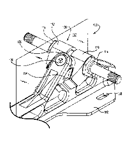
[027] Figure 1 illustrates an embodiment of a truck assembly 100 according to
the
present disclosure. The truck assembly 100 includes a mounting plate 102, a
cushion 104, an
axle assembly 106, a swing pin 108, a first adjustment member 110, a second
adjustment
member 112, a first adjustment nut 114, and a second adjustment nut 116. As
discussed herein,
the first adjustment member 110 and the second adjustment member 112 can be
independently
moved, relative each other, through the use of their respective first
adjustment nut 114, and
second adjustment nut 116. This allows independent adjustment of the first
adjustment member
110 and the second adjustment member 112 relative the cushion 104.
[028] The truck assembly 100 introduces an approach to adjusting the turning
action of
a truck useful for roller skates and/or skate boards that is very different
than traditional
approaches. For the present disclosure, pressure applied to the cushion 104
(through the
4
CA 02773256 2012-03-30
BCH Dkt# 250.0030001
adjustment members 110, 112, as discussed herein) for adjusting the turning
action of the truck
assembly 100 is directed either into or out of a median plane 117that bisects
the truck assembly
100 vertically through the mounting plate 102, the cushion 104, the axle
assembly 106 and the
swing pin 108.
[029] The adjustment members 110, 112 can also be used to apply pressure to
the
cushion 104 independently of each other. This feature of the truck assembly
100 allows for the
option of "tuning" the steering of the truck assembly 100 in a directional
format. That is to say,
it allows the user to put pressure on the cushion 104 in an asymmetrical way
form the right side
or the left side, relative the medial plane 117, of the truck assembly 100.
So, for example, if
steering to the left (in a common pattern for a skater to skate in circles or
laps around the rink in
repetitive left-turn cycle), he/she can adjust the pressure on one side of the
cushion 104
completely independently from the other side thus presenting a benefit to the
user. This is
unique because traditional trucks only offer a single force direction on the
cushion (straight down
or approximately vertical) and does not allow for compensation for a
competitive or recreational
user to focus on a single direction turning radius focus.
[030] Figure 2 illustrates an embodiment of the mounting plate 102. As
illustrated, the
mounting plate 102 includes a first mounting bracket 118 with a first arm 120,
a second arm 122
and a ridge 124. The first arm 120 and the second arm 122 extend parallel to
each other from the
mounting plate 102. The first arm 120 has a first surface 126 defining a first
opening 128
through the first arm 120. The second arm 122 has a second surface 130
defining a second
opening 132 in the second arm 122.
[031] The first opening 128 and the second opening 132 share a rotation axis
134. As
illustrated, the rotational axis 134 is located in the approximate center of
the openings 128 and
132 defined by the first surface 126 and second surface 130, respectively.
Relative a
longitudinal axis 119 of the mounting plate 102, the rotation axis 134 forms
an angle of about
forty-five (45) degrees (as illustrated). It is appreciated that other angles
for the rotation axis 134
relative the longitudinal axis 119 of the mounting plate 102 are also
possible. These can include,
but are not limited to, 10 degrees.
[032] As illustrated, the ridge 124 extends parallel with the rotation axis
134 at least
partially between thefirst arm 120 and the second arm 122. In one embodiment,
the ridge 124
can extend completely between the first arm 120 and the second arm 122. In
addition, the ridge
CA 02773256 2012-03-30
BCH Dkt# 250.0030001
124 can extend up to approximately the first surface 126 and/or the second
surface 130. For the
various embodiments, the ridge 124 can have different heights and/or
thicknesses as desired.
[033] The mounting plate 102 further includes surfaces 136 that define
mounting
openings 138 through the mounting plate 102. A fastener can pass at least
partially through the
mounting opening 138 to allow the mounting plate 102 to be secured to a boot
of a roller skate or
to a board of a skateboard. Such fasteners can include, but are not limited
to, a screw or a
threaded bolt, where a threaded nut can be used with the threaded bolt to
secure the mounting
plate 102.
[034] Figure 3A illustrates an embodiment of the cushion 104. As illustrated,
the
cushion 104 includes a front surface 140 and a rear surface 142 opposite the
front surface 140.
The cushion 104 also includes a first lateral surface 144 and a second lateral
surface 146 that
engage the first adjustment member 110 and the second adjustment member 112,
as discussed
herein. As illustrated, the front surface 140 defines a concave segment 148
and the rear surface
142 defines a notch 150. The notch 150 can receive and seat the ridge 124 of
the first
mountingbracket 118. For the various embodiments, the cushion 104 can be
formed of a
polymer. Examples of suitable polymers include, but are not limited to natural
rubber, synthetic
rubber or polyurethane.For the various embodiments, the cushion 104 can be
formed in a
molding process, such as injection molding or compression molding, among
others. In one
embodiment, the notch 150 is 0.1 inch wide and 0.806 inch long. Other sizes
for the width and
length of the notch 150 are possible.
[035] For the embodiments, when the ridge 124 is seated in the notch 150,
pressure
applied to one of the first lateral surface 144 or the second lateral surface
146 of the cushion 104
can be carried by the ridge 124. In this way, the amount of pressure
transferred through the
cushion 104 from one of the first lateral surface 144 to the second lateral
surface 146, or visa-
versa, can be minimized. As appreciated, the ridge 124 has a height, a length
and a thickness
that, for the given material from which it is produced, can carry this
pressure and/or force as the
truck assembly 100 is used.
[036] Figure 3B illustrates the cushion 104 positioned between the first arm
120 and the
second arm 122 of the first mounting bracket 118 with the ridge seated in the
notch. As
illustrated, together the concave segment 148 of the cushion 104 and at least
a portion of thefirst
arm 120 and the second arm 122 define a socket 152.
6
CA 02773256 2012-03-30
BCH Dkt# 250.0030001
[037] Figure 4A provides an illustration of the axle assembly 106. As
illustrated, the
axle assembly 106 includes a first wheel shaft 154, a second wheel shaft 156
and a truck support
158. The first wheel shaft 154 extends along a central axis 160 from the truck
support 158, while
the second wheel shaft 156 extends along the central axis 160 from the truck
support 158 in
adirection opposite the first wheel shaft 154.
[038] The truck support 158 also includes a third surface 162 that defines an
opening
164 through thetruck support 158, a first tubular shaft 166, a second tubular
shaft 168, a
convexsurface 168, and a guide surface 172 having a predefined shape. When
assembled (as
illustrated in Figure 1 for example), the opening 164 through the truck
support 158 is coaxial
with therotation axis 134 of the first mounting bracket 118.
[039] The first tubular shaft 166is coaxial with the central axis 160
andextends in a
direction of the first wheel shaft 154 away fromthe opening 164 through the
truck support 158.
The second tubular shaft 168is alsocoaxial with the central axis 160
andextends in a direction of
the second wheel shaft 156 away fromthe opening 164 through the truck support
158. Both the
firsttubular shaft 166and the second tubular shaft 168have a threadedsurface
174 that can receive
the first adjustment nut and the second adjustment nut, respectively.
[040] The convex surface 168 has a convex segment 176that seats in the socket
152.
Figure 4B provides an illustration in which the convex segment is seated in
the socket. Figure
4B also provides a view of the guide surface 172of the truck support 158,
where the guide
surface 172 has a predefined shape. As illustrated in the embodiment of Figure
4B, the
predefined shapeof the guide surface 172 has a planar surface 178 with a first
shoulder 180 and a
second shoulder 181(e.g., an angled or sloping surface relative the planar
surface 176). As
discussed more fully herein, the predefined shapeof the guide surface 170
allows for the first
adjustment member 110 and the second adjustment member 112 to each
independently travel
laterally (relative the central axis 160) over at least a portion of the guide
surface 170 without
rotating relative the central axis 160. It is appreciated that other
predefined shapes for the guide
surface 172 are possible (e.g., other shapes that would allow the first
adjustment member 110
and the second adjustment member 112 to each independently travel laterally
(relative the central
axis 160) over at least a portion of the guide surface 170 without rotating
relative the central axis
160).
7
CA 02773256 2012-03-30
BCH Dkt# 250.0030001
[041] Figure 4B, as discussed herein, illustrates the axle assembly106
positioned so that
the convex segment is seated in the socket (as seen in Figure 3B) with the
rotation axis 134
passing through the geometric centers of the first opening 128, the second
opening 132 and the
opening 164 through the truck support 158 (e.g., coaxial). As illustrated in
Figures 1 and 2, the
swing pin 108 passes through the first opening 128 of the first mounting
bracket 118, the
opening 164 through the truck support 158 and at least partially through the
second opening 132
of the first mounting bracket 118. In this way, the swing pin 108 can
releasably join the
cushion104 and the axle assembly 106 to the first mounting bracket 118. As
illustrated in Figure
2, the swing pin 108 can be in the form of a threaded bolt having a shaft 180
with a head 182
having a socket (e.g., a hexagonal socket) to receive a driving tool(e.g., a
hex key) at one end of
the shaft 180 and a surface defining thread 184 at the other end of the shaft
180. The second
surface 130 defining the second opening 132 can include a thread tapped into
the surface 130
that allow for thread 184 of the swing pin 108 to be releasably joined to the
first mounting
bracket 118.
[042] Figure 4B also illustrates an embodiment of the second adjustment member
112
positioned on the axle assembly 106, where the first adjustment member (110)
is not shown so as
to illustrate the thread 174. Figure 5 illustrates an embodiment of the
adjustment member 110,
112 where the description of the adjustment member is applicable to both the
first and the second
adjustment members 110, 112. As illustrated, the adjustment member 110, 112
has a first surface
186, a second surface 188, and a cushion arm 190. The first surface 186
defines an opening 192
that can be mounted at least partially over the first tubularshaft 166 or the
second tubular shaft
168 of the truck support 158. The second surface 188 seats against the guide
surface 172 of the
truck support 158, where thepredefined shape, as discussed herein, allows the
adjustment
member 110, 112 to travel at leastpartially over the guide surface 172 of the
truck support 158
and prevents the first surface 186 of the adjustment member 110, 112from
rotating relative the
centralaxis 160. The cushion arm 190 extends away from both the first surface
186, the second
surface 188. When mounted on the truck support 158, the cushion arm 190 of the
adjustment
member 110, 112 also extends away from the central axis 160 of the truck
support 158 and can
contact the first lateralsurface 144 and the second lateral surface 146,
respectively, of the cushion
104.
8
CA 02773256 2012-03-30
BCH Dkt# 250.0030001
[043] Identical to the first adjustment member 110, the second adjustment
member 112
also has the first surface 186, the second surface 188, and the cushion arm
190 (the second
adjustment member 112 shown in Figure 5, where element number 112 for the
second
adjustment member is shown in parentheses). The second adjustment member 112
includes the
first surface 186 defining the opening 192 that can be mounted at least
partially over the second
tubular shaft 168 of the truck support 158. The second surface 188 seats
against the guide
surface 172 of the truck support 158, where the predefined shape, as discussed
herein, allows the
second adjustment member 112 to travel at least partially over the guide
surface 172 of the truck
support 158 and prevents the first surface 186 of the second adjustment member
112 from
rotating relative the central axis 160. The cushion arm 190 extends away from
both the first
surface 186, the second surface 188. When mounted on the truck support 158,
the cushion arm
190 of the first adjustment member 110 also extends away from the central axis
160 of the truck
support 158 and can contact the second lateral surface 146 of the cushion 104.
[044] Figure 6 provides an illustration of the axle assembly 106, the first
adjustment
member 110 and the second adjustment member 112, as discussed herein. Figure 6
also
illustrates the first adjustment nut 114 and the second adjustment nut 116,
where Figure 7
illustrates the adjustment nut (e.g., either the first adjustment nut 114 or
the second adjustment
nut 116) by itself. As seen in Figure 7, the adjustment nut 114, 116has a
surface 198 defining an
internal thread 101 that reversiblyengages the threaded surface 174 of either
the first tubular
shaft 166 and/or the second tubular shaft 168 of the truck support 158. As the
adjustment nut
114, 116 is rotated relative the threaded surface 174 of the first tubular
shaft 166 or the second
tubular shaft 168, the cushion arm 190 of the adjustment member 110, 112 can
move relative the
first lateral surface 144 and/or the second lateral surface 146 of the cushion
104.
[045] Independent of the first adjustment nut 114, the internal tread of the
second
adjustment nut 116 can reversibly engages the threaded surface 174 of the
second tubular shaft
168 of the truck support 158 to move the cushion arm 190 of the second
adjustment member 112
relative the second lateral surface 146 of the cushion 104. In other words,
the second adjustment
nut 116 can be rotated to move the cushion arm 190 of the second adjustment
member 112
relative the second lateral surface 146 of the cushion 104 independently of
the cushion arm 190
of the first adjustment member 110, and visa-versa.
9
CA 02773256 2012-03-30
BCH Dkt# 250.0030001
[046] Figure 6 also illustrates a bearing 103seated in the opening of the
truck support
158. When assembled (as illustrated in Figure 1 for example), the bearing 103
is coaxial with
the rotation axis 134 of the first mounting bracket 118. The bearing 103 also
includes an inner
diameter 105 that can allow the shaft 180 of the swing pin 108 to pass through
the bearing 103.
[047] The bearing 103 can guide the motion of the axle assembly 106 on the
swing pin
108 (having been releasably secured to the first mounting bracket 118 as
illustrated in Figure 1).
Specifically, the bearing 103 allows the axle assembly 106 to rotate around at
least a portion of
the rotation axis 134, where the interaction of the first and second
adjustment members 110, 112
and the cushion 104 constrain the amount of rotation.
[048] For the various embodiments, the bearing 103 can be a plain bearing or a
roller
element bearing. Examples of a plain bearing can include ajoumal bearing, an
integral bearing,
or a bushing. Examples of a roller element bearing can include a ball bearing,
a cylindrical roller
bearing or a needle bearing, among others.
[049] The truck assembly 100 can also include a washer 107 positioned between
the
truck support 158 and the first arm 120 and/or the second arm 122 of the first
mounting bracket
118. An example of a suitable washer 107 includes, but is not limited to, a
plain washer.The
washer 107 can be formed from a polymer,a metal and/or a metal alloy. Examples
of suitable
polymers include, but are not limited a nylon (i.e., a polyamide) and
polytetrafluoroethylene
(PTFE), among others. Examples of suitable metals and/or metal alloys include
steel, stainless
steel, hardened steel aluminum and titanium, among others.
[050] The truck assembly 100 can be used with a variety of devices. Examples
of such
devices include, but are not limited to, roller skates and skateboards, among
others. The truck
assembly 100 can be mounted to the roller skate or skateboard with fasteners
(e.g., bolts or
screws) that pass through the mounting openings 138 of the mounting plate 102.
When bolts
(seen in Figure 4B) are used as the fastener, a nut and washer can be used to
secure the truck
assembly 100 to the device (e.g., roller skate and/or skateboard).
[051] Referring now to Figure 8, there is illustrated an additional embodiment
of a truck
assembly 109 of the present disclosure. The truck assembly 109 includes the
first mounting
bracket 118-1, as discussed herein, and a second mounting bracket 118-2 on the
mounting plate
113. As with the first mounting bracket 118-1, the second mounting bracket 118-
2includes the
same structures, such as a first arm 120-2, a second arm 122-2and a ridge 124-
2 (seen in Figure
CA 02773256 2012-03-30
BCH Dkt# 250.0030001
9), as discussed herein. As illustrated in Figure 9, the second mounting
bracket 118-2 includes a
first surface 126-2defining a first opening 128-2through the first arm 120-2,
and a second surface
130-2defining a second opening 132-2in the second arm 122-2. The first opening
128-2and the
second opening 132-2 of the second mounting bracket 118-2share a rotation axis
134-2. The
ridge 124-2extends parallel with the rotation axis 134-2 at least partially
between thefirst arm
120-2and the second arm 122-2.The rotation axis 134-1 of the first mounting
bracket 118-1 and
the rotation axis 134-2 of the second mounting bracket 118-2 can intersect at
an angle of
approximately ninety degrees.
[052] The truck assembly 109 further includes cushions 104-1 and 104-2, as
discussed
herein. As discussed, the notch of the cushions 104-1 and 104-2 can receive
and seat each of the
ridges 124-1 and 124-2, respectively,of the mountingbrackets 118-1 and 118-2,
and together the
concave segments and at least a portion of thefirst arms120-1 and 120-2and the
second arms122-
1 and 122-2define each respective socket.
[053] The truck assembly 109 also includes axle assemblies 106-1 and 106-2, as
discussed herein, each having the first wheel shaft 154-1, 154-2, the second
wheel shaft 156-1
and 156-2 and the truck support 158-1, 158-2. As with the truck support 158-1,
there is a surface
defining an opening through the truck support 158-2 that is coaxial with
therotation axis 134-2 of
the second mounting bracket 118-2.
[054] The truck assembly 109 further includes swing pins 108-1 and 108-2. Each
of the
swing pins 108-1 and 108-2 passes through their respective the first openings
128-1, 128-2, the
opening through their respective truck support 158-1, 158-2 and at least
partially through each of
their respective second opening 132-1, 132-2 to releasably join the cushion
104-1, 104-2 and the
axle assemblies 106-1 and 106-2 to the first mounting bracket 118-1 and the
second mounting
bracket, respectively.The truck assembly 109 further includes first adjustment
members 110-1,
110-2, second adjustment members 112-1, 112-2, first adjustment nuts 114-1,
114-2, and second
adjustment nuts 116-1, 116-2, as discussed herein.
[055] The truck assembly 109 also includes a socket 115 that can receive a toe
stop 117
and hold the toe stop 115 through the use of a set bolt 117, where the set
bolt 117 reversibly
clamps the toe stop 115 to the truck assembly 109. The truck assembly 109
further includes
surfaces 136-1 and 136-2 that define mounting openings 138-1 and 138-2 through
the mounting
plate 113.Fasteners, as discussed herein, can pass at least partially through
the mounting
11
CA 02773256 2012-03-30
BCH Dkt# 250.0030001
openings 138-1 and 138-2 to allow the mounting plate 113 to be secured to a
boot of a roller
skate.
[056] Figure 10 provides an illustration of a roller-skate 151 that includes a
boot 153
having a sole 155, and the mounting plate 11 3of the truck assembly 109
secured to the sole 155
of the boot 153. As illustrated, a wheel 157 can be mounted on each of the
first wheel shaft and
the second wheel shaft.
[057] The truck assembly of the present disclosure can be formed from a number
of
different materials. Examples of such materials include, but are not limited
to metals, metal
alloys, and combinations thereof. Examples of metals include, but are not
limited to, aluminum
and titanium, among others. Examples of metal alloys include, but are not
limited to, steel (e.g.,
stainless steel), alloys of aluminum such as 7075 aluminum (among others), and
alloys of
titanium. Many of the components of the truck assembly of the present
disclosure can be
machined using a computer numerical control (CNC) machine tool, which can be
controlled by
computer-aided design (CAD) and/or computer-aided manufacturing (CAM)
programs.
[058] It is to be understood that the above description has been made in an
illustrative
fashion and not a restrictive one. Although specific examples for devices and
methods have been
illustrated and described herein, other equivalent component arrangements
and/or structures
conducive to the truck assembly can be substituted for the specific examples
shown herein. For
example, an axel assembly according to an embodiment of the present disclosure
can be
configured in such a way that the "adjustment members" as discussed herein are
non-adjustable
(e.g., fixed). In one embodiment, the truck support and the cushion arms of
the axel
assemblycan be machined from a single piece of material (e.g. metal alloy). A
shaft can then be
inserted through an opening in the truck support/cushion arm structure to
provide the wheel
shafts discussed herein.
12