Language selection

Search

Patent 2773621 Summary

Third-party information liability

Some of the information on this Web page has been provided by external sources. The Government of Canada is not responsible for the accuracy, reliability or currency of the information supplied by external sources. Users wishing to rely upon this information should consult directly with the source of the information. Content provided by external sources is not subject to official languages, privacy and accessibility requirements.

Claims and Abstract availability

Any discrepancies in the text and image of the Claims and Abstract are due to differing posting times. Text of the Claims and Abstract are posted:

  • At the time the application is open to public inspection;
  • At the time of issue of the patent (grant).
(12) Patent Application: (11) CA 2773621
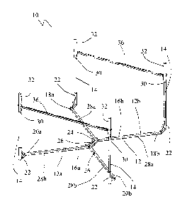
(54) English Title: SUPPORT STAND FOR DISPOSAL BAGS
(54) French Title: SUPPORT POUR SACS JETABLES
Status: Deemed Abandoned and Beyond the Period of Reinstatement - Pending Response to Notice of Disregarded Communication
Bibliographic Data
Abstracts

English Abstract


A support stand for disposal bags includes a base and at
least four posts extending
upwardly from the base. Each post terminates in an upper extremity. An
extendable tip is
positioned at the upper extremity of each post. Each extendable tip is movable
between an
extended position and a retracted position. Extendable tips are maintained in
the extended
position by a locking mechanism. Releasing the locking mechanism on one or
more
extendable tip causes the extendable tip to move to the retracted position
thereby relieving
tension on a disposal bag that is supported in the support stand to avoid
binding between the
disposal bag and the posts.


Claims

Note: Claims are shown in the official language in which they were submitted.

5
What is Claimed is:
1. A support stand for disposal bags, comprising:
a base;
at least four posts extending upwardly from the base, each post terminating in
an
upper extremity;
an extendable tip positioned at the upper extremity of each post, each
extendable tip
being movable between an extended position and a retracted position, each
extendable tip
being maintained in the extended position by a locking mechanism, releasing
the locking
mechanism on one or more extendable tip causing the extendable tip to move to
the retracted
position thereby relieving tension on a disposal bag being supported to avoid
binding between
the disposal bag and the posts.
2. The support stand of Claim 1, wherein the support stand is collapsible and
the base is
comprised of:
a first portion and a second portion, each of the first portion and the second
stand
portion comprising:
a tubular body having a first end and a second end, post receivers position at
each of the first end and the second end;
a linkage on the tubular body for coupling the first portion and the second
portion together.
3. The support stand of Claim 2, wherein each tubular body defines a V shape
with a narrow
bridge member connecting diverging arms, the linkage being positioned along
the narrow
bridge member.
4. The support stand of Claim 1, wherein braces extend between pairs of the
posts, the braces
serving to limit relative movement of the posts under load.
5. The collapsible stand of claim 1, wherein the linkage between the first
portion and the
second portion is a pin connection.

6
6. The collapsible stand of claim 1, wherein the locking mechanism is a
locking pin that
extends through the extendible tip into the post.

Description

Note: Descriptions are shown in the official language in which they were submitted.


CA 02773621 2012-04-11
TITLE
[0001] Support Stand For Disposal Bags /
FIELD
[0002] This relates to the field of stands for holding disposal bags; in
particular, stands
for holding disposal bags which are now supplanting dumpster bins.
BACKGROUND
[0003] U.S.
Patent 5,725,348 (Drake) discloses a vehicle with a lifting apparatus and a
large dumpster bin. Large bags are now being used to replace large dumpster
bins. These
large bags are supported on support stands. As a bag becomes filled, it tends
to expand
outwardly and binds within the stand. This creates difficulties when a vehicle
with a lifting
apparatus comes to lift the large bag from the support stand. What is needed
is a support stand
which addresses this problem of binding.
SUMMARY
[0004] There is
provided a support stand for disposal bags that includes a base with at
least four posts extending upwardly from the base. Each post terminates in an
upper
extremity. An extendable tip is positioned at the upper extremity of each
post. Extendable tips
are movable between an extended position and a retracted position and are
maintained in the
extended position or retracted position by a locking mechanism. Releasing the
locking
mechanism on one or more extendable tip causes the extendable tip to move to
the retracted
position thereby relieving tension on a disposal bag being supported within
support stand to
avoid binding between the disposal bag and the posts.
[0005]
Beneficial results have been seen when the support stand is collapsible and
the
base has a first portion and a second portion. Each of the first portion and
the second stand
portion has a tubular body with a first end and a second end. Post receivers
are positioned at
each of the first end and the second end for receiving posts. A linkage is
provided on the
tubular body for coupling the first portion and the second portion together.
[0006] Further
beneficial results have been seen when each tubular body defines a V
shape with a narrow bridge member connecting diverging arms. The linkage is
positioned

CA 02773621 2012-04-11
2
along the narrow bridge member. Beneficial results have also been seen when
the linkage
between the first portion and the second portion is a pin connection.
[0007] Beneficial results have also been seen when braces extend between
pairs of the
posts and serve to limit relative movement of the posts under load. These
braces provide
additional stability to the support stand.
[0008] Further beneficial results have been shown when the locking
mechanism is a
locking pin that extends through the extendible tip into the post.
BRIEF DESCRIPTION OF THE DRAWINGS
[0009] These and other features will become more apparent from the
following
description in which reference is made to the appended drawings, the drawings
are for the
purpose of illustration only and are not intended to be in any way limiting,
wherein:
FIG. 1 is a perspective view of a support stand for disposal bags
FIG. 2 is a side elevation view, partially in section, of the support stand in
the
extended position.
FIG. 3 is a side elevation view, partially in section, of the support stand in
the
retracted position.
FIG. 4 is a top plan view of a portion of the base of the support stand shown
in
FIG. 1.
DETAILED DESCRIPTION
[0010] A support stand for disposal bags generally identified by
reference numeral 10,
will now be described with reference to FIG. 1 through 4.
Structure and Relationship of Parts:
[0011] Referring to FIG. 1, a support stand for disposal bags 10 has a
base 12 with at
least four posts 14 extending upwardly from base 12. In the embodiment shown,
base 12 is
made up of a first portion 12a and a second portion 12b which allows support
stand 10 to be
collapsed for storage or transport. Each of first portion 12a and second
portion 12b have a

CA 02773621 2012-04-11
3
tubular body 16a and 16b with a first end 18a and 18b and a second end 20a and
20b with
post receivers 22 positioned at each of first end 18a and 18b and second end
20a and 20b. A
linkage 24 on tubular body 16a and 16b couples first portion 12a and second
portion 12b
together. In the embodiment shown, linkage 24 is a pin connection, however it
will be
understood that different types of linkages such as clamps may be used.
Referring to FIG. 4,
it is preferable that tubular body 16 be a "V" shape with a narrow bridge
member 26
connecting diverging arms 28a and 28b and linkage 24 positioned along narrow
bridge
member 26 of tubular body 16. Referring to FIG. 1, each post 14 terminates in
an upper
extremity 30. An extendable tip 32 is positioned at upper extremity 30 of each
post 14 and is
movable between an extended position, shown in FIG. 2, and a retracted
position, shown in
FIG. 3.
[0012] Referring
to FIG. 2, extendable tips 32 are each maintained in the extended
position by a locking mechanism 34 and may be extended or retracted
independently of each
other. In the embodiment shown, locking mechanism 34 is a locking pin 35 that
extends
through extendible tips 32 into posts 14. Referring to FIG. 3, releasing
locking mechanism 34
on one or more extendable tips 32 causes extendable tip 32 to move to the
retracted position
thereby relieving tension on a disposal bag being supported (not shown), to
avoid binding
between the disposal bag and posts 14. To help stabilize support stand 10,
braces 36 may
extend between pairs of posts 14. In the embodiment shown, braces 36 are
connected to
extendable tips 32, however braces 36 may be positioned lower on posts 14.
Braces 36 are
shown as being removable, however braces 36 may be welded into position.
Removable
braces 36 has a first connection 38 which connects with a second connection 40
positioned on
extendible tips 32 or posts 14.
Operation:
[0013] Referring
to FIG. 1, support stand 10 is placed in position. In the embodiment
shown, first portion 12a and second portion 12b are connected by linkage 24.
Posts 14 are
held substantially vertically within post receivers 22 with extendible tips 32
positioned on
upper extremities 30. Braces 36 are connected to extendable tips 32 to provide
additional
stabilization to support stand 10. Referring to FIG. 2, extendable tips 32 are
moved to the

CA 02773621 2012-04-11
4
extended position and held in position by locking pin 35. A disposal bag, not
shown, is held
open on extendable tips 32 to facilitating filling of the disposal bag. As
disposal bag fills, it
expands outwards. Referring to FIG. 3, when disposal bag is to be removed from
support
stand 10, locking pins 35 are removed enabling extendable tips 32 to move to
the retracted
position. With extendable tips 32 in the retracted position, the disposal bag
is less likely to
bind against posts 14 as the disposal bag lifted from support stand 10 by a
mechanical lift
arm.
[0014] In this
patent document, the word "comprising" is used in its non-limiting sense to
mean that items following the word are included, but items not specifically
mentioned are not
excluded. A reference to an element by the indefinite article "a" does not
exclude the
possibility that more than one of the element is present, unless the context
clearly requires that
there be one and only one of the elements.
[0015] The following claims are to be understood to include what is
specifically illustrated
and described above, what is conceptually equivalent, and what can be
obviously substituted.
The scope of the claims should not be limited by the preferred embodiments set
forth in the
examples, but should be given the broadest interpretation consistent with the
description as a
whole.

Representative Drawing
A single figure which represents the drawing illustrating the invention.
Administrative Status

2024-08-01:As part of the Next Generation Patents (NGP) transition, the Canadian Patents Database (CPD) now contains a more detailed Event History, which replicates the Event Log of our new back-office solution.

Please note that "Inactive:" events refers to events no longer in use in our new back-office solution.

For a clearer understanding of the status of the application/patent presented on this page, the site Disclaimer , as well as the definitions for Patent , Event History , Maintenance Fee  and Payment History  should be consulted.

Event History

Description Date
Inactive: Dead - No reply to s.30(2) Rules requisition 2016-10-31
Application Not Reinstated by Deadline 2016-10-31
Deemed Abandoned - Failure to Respond to Maintenance Fee Notice 2016-04-11
Inactive: Abandoned - No reply to s.30(2) Rules requisition 2015-10-29
Inactive: S.30(2) Rules - Examiner requisition 2015-04-29
Inactive: Report - QC failed - Minor 2015-04-27
Inactive: Cover page published 2014-06-16
Letter Sent 2014-03-10
Request for Examination Requirements Determined Compliant 2014-03-04
Request for Examination Received 2014-03-04
All Requirements for Examination Determined Compliant 2014-03-04
Application Published (Open to Public Inspection) 2013-10-11
Inactive: First IPC assigned 2012-09-19
Inactive: IPC assigned 2012-09-19
Filing Requirements Determined Compliant 2012-04-23
Inactive: Filing certificate - No RFE (English) 2012-04-23
Application Received - Regular National 2012-04-23
Small Entity Declaration Determined Compliant 2012-04-11

Abandonment History

Abandonment Date Reason Reinstatement Date
2016-04-11

Maintenance Fee

The last payment was received on 2015-04-10

Note : If the full payment has not been received on or before the date indicated, a further fee may be required which may be one of the following

  • the reinstatement fee;
  • the late payment fee; or
  • additional fee to reverse deemed expiry.

Please refer to the CIPO Patent Fees web page to see all current fee amounts.

Fee History

Fee Type Anniversary Year Due Date Paid Date
Application fee - small 2012-04-11
MF (application, 2nd anniv.) - small 02 2014-04-11 2014-03-04
Request for examination - small 2014-03-04
MF (application, 3rd anniv.) - small 03 2015-04-13 2015-04-10
Owners on Record

Note: Records showing the ownership history in alphabetical order.

Current Owners on Record
MATTHEW HORVATH
Past Owners on Record
None
Past Owners that do not appear in the "Owners on Record" listing will appear in other documentation within the application.
Documents

To view selected files, please enter reCAPTCHA code :


To view images, click a link in the Document Description column. To download the documents, select one or more checkboxes in the first column and then click the "Download Selected in PDF format (Zip Archive)" or the "Download Selected as Single PDF" button.

List of published and non-published patent-specific documents on the CPD .

If you have any difficulty accessing content, you can call the Client Service Centre at 1-866-997-1936 or send them an e-mail at CIPO Client Service Centre.


Document
Description 
Date
(yyyy-mm-dd) 
Number of pages   Size of Image (KB) 
Representative drawing 2013-09-13 1 10
Abstract 2012-04-11 1 15
Description 2012-04-11 4 158
Claims 2012-04-11 2 38
Drawings 2012-04-11 4 59
Cover Page 2014-06-16 2 42
Filing Certificate (English) 2012-04-23 1 157
Reminder of maintenance fee due 2013-12-12 1 111
Acknowledgement of Request for Examination 2014-03-10 1 177
Courtesy - Abandonment Letter (R30(2)) 2015-12-10 1 165
Courtesy - Abandonment Letter (Maintenance Fee) 2016-05-24 1 172
Correspondence 2012-04-23 1 47
Fees 2015-04-10 1 24