Note: Descriptions are shown in the official language in which they were submitted.
CA 02773787 2012-03-09
WO 2011/029157 PCT/AU2010/001186
- 1 -
DISASSEMBLY OF INTER-FITTING COMPONENTS
Technical Field
The present disclosure relates to tools for facilitating
the disassembly of components which are fitted together
generally in an intimate manner for a period of use and
which need to be disassembled for servicing purposes, such
as excavation tooth assemblies.
Background
Excavation teeth are provided on the digging edge of
various pieces of digging equipment, such as dredging
cutter heads, the buckets of front end loaders, etc.
Excavation teeth are formed of a number of components,
commonly a tooth point and an adapter. The reason why
excavation teeth are formed of a number of components is
to avoid having to discard the entire tooth when the
ground engaging part of the tooth (i.e. the point) is worn
or broken.
For mining buckets, for example, excavation points are
typically connected to a leading edge of the bucket by way
of an adaptor which is secured to the bucket lip. The
adapter not only acts as a mounting for the point but also
acts to reinforce and strengthen the lip. Each point is
conveniently fixed to its respective adapter by a suitable
locking mechanism such as a transversely extending
engaging pin passing through the external walls of the
point and through an aligned cavity in a forwardly
extending nose of the adapter. Generally, the adapter has
a chosen profile matched by an interior cavity of the
point.
CA 02773787 2012-03-09
WO 2011/029157 PCT/AU2010/001186
2 -
After a period of service (which in harsh conditions can
be quite short e.g. a few hours), the point will become
worn and need to be quickly and safely removed from the
adaptor and replaced.
It has been found that frequently there is difficulty'in
removing the point due to it being jammed onto the adapter
as a result of the ingress of fines and the effect of the
considerable loads applied to the point along its tip
during digging operations. Fines and other material
become packed between a point and an adapter and various
techniques have been necessary to remove points from
adapters including, levering, thermal gouging and
destructive processes. The cost of downtime is
considerable as well as the demands on operators who are
seeking to change points in remote worksite locations
where safety considerations are very important. For
example, if hammers are used in the process of disengaging
components, there is a risk of injury including a risk
from flying chips of metal and debris. Furthermore, such
operations are labour intensive.
Summary of the Disclosure
Disclosed is a tool for disassembling an excavation tooth
assembly comprising first and second tooth members, the
tool comprising:
a body comprising a driven portion and first and
second legs, the legs extending generally in a common
plane and defining an assembly receiving cavity
therebetween, each of the first and second legs comprising
a wedge portion adjacent the assembly receiving cavity
which tapers toward a distal end of the respective leg, in
CA 02773787 2012-03-09
WO 2011/029157 PCT/AU2010/001186
3 -
use the tool being adapted to locate over a join defined
between the first and second tooth members such that the
wedge portion of the first and second legs locates within
the join and wherein in use a force applied to the driven
portion is arranged to drive the wedge portion further
into the join so as to cause separation of the first and
second tooth members in a direction transverse to the
movement of the first and second legs.
In one form the body further comprises a main portion from
which the first and second legs depend.
In a particular form the legs are spaced apart and join
with the main portion to form a U-shaped configuration.
In a particular form the legs extend from a lower surface
of the main portion and the driven portion is mounted on
an upper surface of the main portion opposite the lower
surface.
In one form the driven portion comprises a coupling
portion adapted to couple to a device for imparting the
force. In addition, in a particular form, the driven
portion further comprises a shank which extends from the
upper surface of the main portion to the coupling portion.
In one form the coupling portion is spaced apart from the
main portion such that, in use, movement of the coupling
portion in a direction generally perpendicular to a
longitudinal axis of the shank causes the wedge portion to
impart a lateral force to at least one of the tooth
members.
CA 02773787 2012-03-09
WO 2011/029157 PCT/AU2010/001186
4 -
In a particular form the driven portion comprises an
enlarged head located on the main portion.
In one form each of the legs further comprise an outer
portion adjacent the wedge shaped portion which is of
thicker width that the wedge shaped portion.
In one form the first tooth member is an adaptor and the
second tooth member is a point of an excavation tooth
assembly.
In a second aspect there is disclosed a method of
disassembling an excavation tooth assembly comprising
first and second tooth members which are coupled together
such a gap is defined at a join between the two assembled
members, the method comprising forcing a wedge into the
gap in a direction transverse to a longitudinal axis of
the excavation tooth assembly so as to cause separation of
the first and second tooth members, the separation being
generally in the direction of the longitudinal axis of the
assembly.
In one form the force applied to the wedge is a percussive
force. In a particular form the method comprises
utilising a jack-hammer (or other suitable force imparting
device) to apply the percussive force.
In one form a further gap is located on an opposite side
of the join, the method further comprising forcing a
second wedge into the further gap in unison with the
forcing of the first wedge.
In another aspect there is disclosed an excavation tooth
CA 02773787 2012-03-09
WO 2011/029157 PCT/AU2010/001186
- 5 -
member adapted to be mounted on a body portion of a
supporting tooth member, the excavation tooth member
having an end structure which at least partially surrounds
a cavity in which the body portion of the supporting tooth
member fits;
the end structure having a raked portion defining an
abutment surface arranged so that an inwardly tapering gap
is defined between the abutment surface and a confronting
portion of the supporting tooth member; whereby the
members may be disassembled by application of a tool
having a wedge shaped element which is arranged to be
driven into the gap.
In another aspect there is disclosed an excavation tooth
support member comprising a body portion adapted to mount
a second tooth member, the body portion comprising a
shoulder section having a raked portion defining an
abutment surface arranged so that an inwardly tapering gap
is defined between the abutment surface and a confronting
end structure of the second tooth member when in an
assembled state; whereby the members may be disassembled
by application of a tool having wedge shaped element which
is arranged to be driven into the gap.
In yet another aspect there is disclosed an excavation
tooth system comprising first and second excavation tooth
members, the first and second tooth members being
assembled such that a body portion of the first tooth
member is located substantially within a socket defined in
a body of the second tooth member, the system further
comprising a disassembly tool comprising a wedge portion
which is arranged to locate in gap defined at a join
between the first and second tooth members, in use the
CA 02773787 2012-03-09
WO 2011/029157 PCT/AU2010/001186
6 -
wedge portion of the tool being arranged to be driven into
the gap so as to cause separation of the first and second
tooth members in a direction transverse to the movement of
the wedge portion.
In a particular form the second tooth member at a joining
end comprises an end structure which at least partially
surrounds the socket and the body portion of the first
tooth member includes a shoulder section defined on
opposite walls thereof which are closely spaced from the
end structure whereby gaps are defined.
In one form, one or both of the first and second tooth
members of the excavation tooth system is in accordance
with one of the tooth members or tooth support members of
the second and third aspects.
In one form the disassembly tool is the tool as described
in accordance with the first aspect, whereby the legs of
the tool locate in the respective gaps to affect the
separation.
In a particular form the tool further comprises a force
imparting device coupled to the tool which is arranged to
impart the force.
In one form the force imparting device comprises a
jackhammer arranged to impart a percussive force for
separating the tooth members.
In accordance with a further aspect there is provided a
mount for a disassembly tool for an excavation tooth
assembly comprising first and second tooth members, the
CA 02773787 2012-03-09
WO 2011/029157 PCT/AU2010/001186
- 7 -
mount comprising:
a mounting portion arranged to detachably mount to
one or both of the first and second tooth members; and
a reaction portion connected to or integrally formed
s with the mounting portion and arranged in use to be spaced
from the first and second tooth members, the reaction
portion being arranged to mount a force actuating device
which, in use, is arranged to impart a force to the
disassembly tool so as to cause separation of the first
and second tooth members, wherein the reaction portion is
arranged to accommodate the reaction loading induced by
the force actuating device.
In one form the reaction loading experienced by the mount
as it drives the disassembly tool is resisted by
connection of the securing portion to the first and/or
second tooth member.
In a particular form the mount further comprises a guide
portion arranged to guide movement of the disassembly tool
under the force imparted by the force actuating device.
In one form, the guide portion retains the disassembly
tool after the separation has been affected.
In one form the guide portion comprises a channel arranged
to receivingly guide an arm coupled to the disassembly
tool.
In one form the mounting portion comprises a pair of
clamping legs each having a first end which couples to a
body of the mount and a second end comprising a coupling
portion which, in use, locates within a cavity provided on
a body of the first and/or second tooth member. The
CA 02773787 2012-03-09
WO 2011/029157 PCT/AU2010/001186
8 -
cavities may, in ordinary use, be arranged to receive an
engaging pin of a locking mechanism for maintaining the
first and second tooth members in an assembled
relationship.
In a particular form the force actuating device comprises
a hydraulic or pneumatic ram.
In one form the reaction portion comprises a mounting
cradle arranged to couple to the disassembly tool and
which mounts a body of the ram.
In one form the reaction portion further comprises an
abutment structure which is spaced apart from and located
in substantially the same plane as the mounting cradle,
such that in use an arm of the hydraulic ram bears against
the abutment structure to thereby cause the disassembly
tool to be driven toward the tooth assembly.
In one form the mount further comprises a lug arranged to
receive a hook of a lifting apparatus. For example, the
lug may be shaped so as to receive a hook of a hoist or
crane which in turn may advantageously manoeuvre into
place and hold the apparatus during the disassembly
operation. Once disassembled, the crane can then readily
remove the worn tooth member which is still secured to the
mount.
In a particular form the mount further comprises an
adjustment mechanism arranged to adjust a retaining angle
of the disassembly tool with respect to the tooth assembly
for suitably aligning the tool (e.g. as a result of side
wall variation due to wear). In another embodiment, the
CA 02773787 2012-03-09
WO 2011/029157 PCT/AU2010/001186
- 9 -
adjustment mechanism may alternatively or additionally
apply a separating force between the mount and tooth
member(s) to which it is coupled for increasing the
stability of the apparatus. The adjustment mechanism may
be in the form of a bolt assembly. A bolt retained by the
bolt assembly may be screwed downwardly such that an end
bears down on the tooth member.
In one form the adjustment mechanism comprises an
internally threaded housing retaining a bolt, an end of
which is in contact with a surface of the first and/or
second tooth member such that turning the bolt causes the
retaining angle to change.
In a particular form the mounting portion comprises a
lower frame defining a base and upwardly extending arms
which project partly into a gap between the first and
second tooth members in a bottom region and the reaction
portion comprising an upper frame adapted to be connected
to the lower frame and providing an abutment structure for
receiving one end of a hydraulic ram, the other of which
is adapted to be applied to the disassembly tool.
In one form at least one of the mounting portion and
reaction portion comprises guide arms extending around the
frame to guide the tool slidingly along the frame as a
wedge portion of the tool is inserted into the gap.
In yet another aspect there is disclosed a disassembly
apparatus comprising a mount as previously disclosed
coupled to a'tool as disclosed in accordance with the
first aspect.
CA 02773787 2012-03-09
WO 2011/029157 PCT/AU2010/001186
- 10 -
In accordance with another aspect there is provided a
disassembly tool for an excavation tooth assembly
comprising first and second tooth members, the disassembly
tool comprising:
a body comprising a wedge portion which is arranged
to locate in a gap defined at a join between the first and
second tooth members; and
a shank extending from the body to a coupling portion
adapted to couple to a device arranged to impart a drive
force to the wedge portion, such that as the drive force
is imparted the wedge portion is driven into the gap to
separate the first tooth member from the second tooth
member.
In a particular form the tooth assembly of the disassembly
tool, apparatus, mount and/or method in accordance with
any one of the previously disclosed aspects comprises a
combination of the following excavation tooth members: a
digging point, adaptor, mid-adaptor, end adaptor, plate
lip adaptor and cast lip integral nose.
In accordance with a still further aspect there is
provided a tool for removing a ground engaging point from
an adapter to which it is secured, the point at its rear
end having a collar extending substantially in a plane
normal to be axis of the point and surrounding a cavity
into which a nose of the adaptor fits, the adapter having
a body structure extending therearound and closely spaced
from the collar of the point whereby gaps are defined;
the tool comprises a body portion and a first and
second depending legs shaped and configured to be inserted
into the gaps on opposite sides of the point, the body
portion of the tool being adapted to receive force to
CA 02773787 2012-03-09
WO 2011/029157 PCT/AU2010/001186
- 11 -
drive the legs into the gaps, each of the legs having a
tapering structure adapted to engage on respective sides
of the collar and the corresponding body portion of the
adapter as the legs are driven into the gaps;
whereby in a wedging action the tool can be driven to
force apart the point and the nose.
In accordance with another aspect the present invention
provides a mining bucket mid-adaptor for mounting on the
nose of an end adapter integrally formed into a lip of a
mining bucket, the mid-adaptor having at its rear end a
collar which surrounds a cavity into which the nose fits;
the collar having at least a portion thereof defined
by an abutment surface extending at a shallow angle to the
plane normal to the axis of the mid-adaptor so that the
adjacent gap between the surface and the confronting
portion of the end adapter is wider near one edge of the
mid-adaptor and narrower in a central region;
whereby the parts may be disengaged by the
application of a tool having wedge shaped elements
arranged to be driven into the adjacent gaps.
Detailed Description of the Drawings
Embodiments will now be given by way of example with
reference to the accompanying drawings in which:
Figure 1 is a side elevation of a first embodiment of
a digging point for mounting on an adapter;
Figure 2 is a perspective view from the rear showing
the point of Figure 1;
Figure 3 is a perspective view of an adapter having a
nose in which the point is adapted to be mounted;
Figure 4 is a side view of the adapter on which the
CA 02773787 2012-03-09
WO 2011/029157 PCT/AU2010/001186
- 12 -
point is assembled and with a disengagement tool offered
up for use in disengaging the parts;
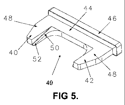
Figure 5 is a perspective view of the tool for
disengaging the parts;
Figure 6 is a front elevation of the tool of
Figure 5;
Figure 7 is a side elevation of the tool of Figure 5;
Figure 8 is a side view on a large scale as part of a
second embodiment of digging point with an altered profile
in the collar region at the rear open end of the point;
Figure 9 is a rear perspective view of the digging
point of Figure 8;
Figure 10 is a plan view of the rear portion of the
digging point of Figure 8;
Figure 11 is a side elevation view of an adaptor in
accordance with an embodiment;
Figure 12 is a front elevation of the adaptor of
Figure 11;
Figure 13 is a sectional plan view of the digging
point of Figure 8 mounted on an adapter and taken along
the line XI-XI of Figure 14;
Figure 14 is a sectional side elevation of the
digging point and adapter of Figure 13 and taken along the
line XII-XII of Figure 13;
Figure 15 is a perspective view of a second
embodiment of tool for use particularly with the point of
Figure 8;
Figure 16 is a perspective view from the rear of the
tool of Figure 15;
Figure 17 is a perspective view of the tool of
Figure 15 with its mounting frame;
Figure 18 is a front elevation of the tool of
Figure 17;
CA 02773787 2012-03-09
WO 2011/029157 PCT/AU2010/001186
- 13 -
Figure 19 is a side elevation of the tool of
Figure 18;
Figure 20 is a sectional side elevation taking along
the line A-A of Figure 18;
Figure 21 is a perspective view of the digging tooth
and adapter with the tool offered up for disengaging the
parts and corresponding to Figure 14;
Figure 22 is a view corresponding to Figure 21 from
the rear view;
Figure 23 is a perspective view of a digging tooth
assembly, mount and tool offered up for disengaging the
parts in accordance with another embodiment;
Figure 24 is a view corresponding to Figure 23 from
the rear;
Figure 25 is a view corresponding to Figure 23 from
the side;
Figure 26 is a view corresponding to Figure 23 from
the front;
Figure 27 is a rear perspective view of the mount and
tool only of Figure 23;
Figure 28 is a side elevation view of Figure 27;
Figure 29 is an end elevation of Figure 27;
Figure 30 is a front elevation of Figure 27;
Figure 31 is a rear perspective view of the assembly
of Figure 23 whereby the wedge of the tool is facing
towards the point.
Figures 32 to 35 show various engineering views of a
tool according to a further embodiment;
Figures 36 is an isometric view of the tool and
mount, in accordance with an embodiment;
Figure 37 is an isometric view of the tool and mount
of Figure 36 secured to a point and adaptor assembly;
Figure 38 is a side view of the Figure 27 tool and
CA 02773787 2012-03-09
WO 2011/029157 PCT/AU2010/001186
- 14 -
mount offered up for use with a cast lip adaptor assembly;
Figure 39 is a side view of Figure 38 with the point
removed; and
Figure 40 is an exploded view of a bucket lip showing
the mid adaptor and point, in accordance with an
embodiment.
Figures 41 through 43 are engineering views of a
mount and tool, in accordance with yet a further
embodiment.
Detailed Description of Embodiments
The following description relates to disassembly tools,
mounts and corresponding methods of use, for disassembling
an excavation tooth assembly comprising first and second
tooth members. While specific embodiments are hereafter
described in the context of an excavation tooth assembly
comprising a first tooth member in the form of a digging
point and a second tooth member in the form of an adaptor,
it will be understood that embodiments are equally
applicable for disassembling other combinations of tooth
members selected from the non-exhaustive group comprising
points, adaptors, mid-adaptors, end adaptors, plate lip
adaptors, cast lip integral noses and the like. Such
excavation teeth members are commonly found on dredger
cutting head assemblies, drag line bucket assemblies,
excavation buckets, electric rope shovels and the like.
With reference to Figures 1 and 2 there is shown a tooth
member in the form of a digging point 10 which is arranged
to be mounted on the nose 12 of an adapter 14 (shown in
isolation in Figure 3), such that a gap 4 is created at a
join between the digging point 10 and adaptor 14. Such an
CA 02773787 2012-03-09
WO 2011/029157 PCT/AU2010/001186
- 15 -
assembled configuration is depicted in Figure 4.
In more detail, the point 10 has an elongate digging tip
16 extending from a main body 18 within which a complex
shape cavity is provided, the cavity having a profile to
match intimately the shape of the nose 12 of the adapter.
The body 18 has side walls 22 having aligned cavities 24
which align with a transverse cavity 26 extending through
the adapter. The cavities 24 are of a generally oval
shape and taper in dimension from the inside wall to the
outside face of side wall 22. The rear open end of the
point terminates in a peripheral end structure (in the
illustrated embodiment being in the form of a collar 30)
which confronts but is spaced from a confronting
shoulder 32 from the body of the adapter. As shown in
Figure 1, the collar 30 is substantially in a plane
transverse to the longitudinal axis of the point.
In the illustrated embodiment, the adapter 14 mounts
within its transverse cavity an axially expandable locking
element 33. Upon engagement of the point on the nose of
the adapter, a locking tool is used to axially expand the
lock so it extends into the cavities 24 in firm engagement
to retain the point on the adapter.
After a period of service, which can be short in harsh
conditions, the digging point 10 may become heavily eroded
and in need of replacement. Typically the adapter will be
fixed to the lip of a carrying bucket of large dimensions
and the point projects from this lower lip for digging
purposes. Figure 4 depicts the assembly with a typical
worn point ready to be removed.
CA 02773787 2012-03-09
WO 2011/029157 PCT/AU2010/001186
16 -
Disassembly Tool
Embodiments provide a tool which, in its most basic form,
comprises a wedge shaped element which can be driven into
the gap 4 in a direction transverse to a longitudinal axis
of the excavation tooth assembly, so as to cause
separation of the point and adaptor.
Figure 4 shows offered up for use one such disassembly
tool being a first embodiment of the invention. The tool
is shown in more detail in Figures 5 to 7 and comprises a
main body 44 having the form of a transverse cross-bar 44.
First and second legs 40, 42 depend from the cross-bar 44.
A driven portion in the form of an abutment head 46 is
integrally formed with the transverse cross-bar 44 for
receiving hammer blows or optionally, force otherwise
applied for example through a hydraulic ram, pneumatic
jackhammer, etc. Each of the legs 40, 42 in the
illustrated embodiment has a robust body 48 chamfered on
the exterior edge and an integrally formed flange 50 which
has a wedge shaped portion in the form of a ramp surface
52. The legs 40, 42 each extend from the cross-bar 44
generally in a common plane to define an assembly
receiving cavity 49. In the illustrated embodiment, the
legs 40, 42 are spaced apart and join with the transverse
cross-bar 44 to form a U-shaped configuration.
In use, and as shown in Figure 4, the ramp surfaces 52 of
the legs 40, 42 engage with side portions 54 of the
collar 30 of the point and rear surfaces 56 of the legs
engage with the confronting shoulder side portions of the
adapter 14. The tool is adapted to be hammered vertically
downwardly so as to cause separation of the point 10 from
the adapter 14 in a direction transverse to the movement
CA 02773787 2012-03-09
WO 2011/029157 PCT/AU2010/001186
- 17 -
of the first and second legs. It has been found that
after a period of service, fines compact in the zone
between the point and the adapter which has been the
subject of a high level of axial force during the digging
operations and frequently the point becomes jambed on the
adapter. Thus, this embodiment provides a tool which in an
inexpensive but simple matter permits rapid and enhanced
separation of the point and the nose in a manner which is
safe and easily effected with a simple tool by a single
operator.
An alternative form of the disassembly tool is shown in
Figures 32 to 35. According to this embodiment, the
disassembly tool 140 further comprises a coupling portion
which allows the tool 140 to be coupled to a force
imparting device for imparting the necessary force to
drive the wedge portions 52 of the depending legs 40, 42
into the gap 4, for separating the assembled tooth
members. In the illustrated embodiment, the drive force
applied to the disassembly tool 142 is a percussive force
and the device utilised to impart the percussive force is
a pneumatic jack hammer 143 (although it will be
understood by persons skilled in the art that other
devices may equally be suited for such an application,
including hammer drills, non-pneumatic jack hammers and
the like).
In more detail, and with particular reference to Figures
32 and 33, a shank 142 extends from a top plate 144 which
is provided on an upper surface of the transverse cross
bar 44. A coupling portion 148 is provided at a distal
end 146 of the shank 142 and has a profiled head (in the
illustrated embodiment the head has a hex-bolt profile for
CA 02773787 2012-03-09
WO 2011/029157 PCT/AU2010/001186
- 18 -
allowing the device to suitably grip the shank, although
it will be understood that other profiles may be equally
applicable), which is adapted to be received in a
correspondingly shaped socket provided on the pneumatic
jack hammer 143. This coupled arrangement is best shown
in Figures 34 and 35. A handle 150 is provided for
manoeuvring the tool 140.
In use, the tool 140 is positioned between the point and
adaptor in much the same manner as described for the
Figure 4 embodiment. Once suitably positioned, the
pneumatic jack is turned on (e.g. by an operator standing
on one side of the assembly) which in turn applies a
repeated impact/percussive force for driving the wedge
downwardly into the gap, causing the adaptor and point to
separate in a direction generally transverse to the
movement of the tool. In the illustrated embodiment, the
coupling portion 148 is spaced apart from the top plate
144 such that movement of the coupling portion in a
direction perpendicular to a longitudinal axis of the
shaft during operation of the tool 140 causes the wedge
portion to impart a lateral force to at least one of the
first and second tooth members for assisting separation of
the excavation tooth assembly (i.e. once the wedge has
sufficiently separated the assembled parts for allowing
the lateral movement).
Tooth Members
In a particular arrangement, the point (or other suitable
tooth member) may have a rear profile which cooperates
with the disassembly tool for facilitating separation.
Figures 8 and 9 show one such arrangement. According to
the illustrated embodiment, the collar 30, or equivalent
CA 02773787 2012-03-09
WO 2011/029157 PCT/AU2010/001186
- 19 -
end structure, comprises a raked portion defining an
abutment surface arranged so that an inwardly tapering gap
is defined between the abutment surface and a confronting
portion of the adaptor. In more detail, the collar 30 is
raked so as to form angled flat side faces 60 extending at
about 5 from the general plane 61 defined as normal to
axis 62 of the point (as best shown in Figure 8). The
flat faces 60 merge with the original collar profile at
merge location 63 and extend to the upper edge 64 of the
side wall where a concave shoulder 65 continues to merge
the central upper portion of the collar 30.
Equally, the adaptor (or other tooth member support) on
which the point mounts may comprise a raked portion for
co-operating with the disassembly tool. One such example
embodiment is shown in Figures 11 and 12. According to
such an embodiment a raked portion 35 is provided on the
adaptor shoulders 32 thereby defining an abutment surface
37, arranged so that an inwardly tapering gap is defined
between the abutment surface 37 and the collar 30 when in
an assembled state.
In one form, the raked portion may be on only one of the
inter-fitting tooth members. In another form, the raked
portion may be on both tooth members.
Tool Mounts
In an embodiment the tool may be coupled to a mount for
facilitating disassembly of the tooth members. In an
embodiment the mount comprises a mounting portion arranged
to detachably mount to one or both of the adaptor and
point. The mount further comprises a reaction portion
which is connected to, or integrally formed with, the
CA 02773787 2012-03-09
WO 2011/029157 PCT/AU2010/001186
- 20 -
mounting portion and arranged to be spaced apart from the
point and adaptor. A force actuating device couples to
the mount to impart a force to the tool so as to cause the
separation. Advantageously, the reaction portion is
arranged to accommodate the reaction loading induced by
the force actuating device.
One such mount is shown in Figures 13 to 22. In this
embodiment, a complimentary disassembly tool is provided
to be forced transversely to the axis of the point into
the gap between the flat faces 60 and the confronting
shoulder of the adapter. Figures 13 and 14 show the tool
initially offered up and ready for the application of
force from a hydraulic ram 62.
The assembled tool and mount is shown in Figures 14 and 17
to 20 and comprises a generally U-shaped engagement tool
64 shown in more detail in Figures 15 and 16, a U-shaped
lower frame 66 and a top frame 68 which carries an
abutment pad 70 which compliments another abutment pad 72
carried on a cross-bar 74 of the engagement tool. As
shown in Figure 14 a force actuating device in the form of
a hydraulic ram 62 is adapted to be located between the
pads 70 and 72 and application of hydraulic force forces
the engagement tool 64 downwardly to slide over the lower
frame 66 and to slide into the wedge shaped gap between
the side faces 60 of the point and the confronting surface
of the shoulder of the adapter.
Referring now to Figures 15 and 16, the tool 64 has side
legs 76 extending from the cross-bar 74 and carrying
respective guide arms 77 which extend from each leg 76 to
provide an engagement surface 80 for sliding over the
CA 02773787 2012-03-09
WO 2011/029157 PCT/AU2010/001186
- 21 -
lower frame. Each leg has an inwardly directed tapered
flange 82 terminating in a thin tip 84.
Installation on an assembled point and adapter is shown in
Figures 21 and 22. Installation is achieved by firstly
sliding the lower U-shaped frame 66 up underneath the
ground engaging tool so that the bottom bar 78 engages
between the bottom portion of the collar 30 and a
confronting shoulder of the nose of the adapter. The
engagement tool 64 has its arms 77 engaged around the
upper part of the legs of the U-shaped frame 66 and it is
slid down so that wedge shaped flanges 82 engage against
the flat side faces 60 of the point. The upper frame 68
is then secured by nuts and bolts to the top of the lower
frame. The hydraulic ram 62 is then inserted between the
abutment blocks 70 and 72 and actuated to expand the ram
thereby taking up the clearance with continued application
of hydraulic pressure then forcing the engagement tool 64
between the point and the adapter to separate the parts.
This embodiment thus offers a speedy, very safe and single
operator action reliably to remove the point from the
adapter.
A further embodiment of a mount which employs a hydraulic
ram for affecting separation is shown in Figures 23
through 30 (again like reference numerals are used to
indicate like parts, as hereinbefore described). In this
further embodiment, the mount 71 couples to a slightly
modified disassembly tool to that previously described,
for affecting the separation operation. As shown
specifically in Figure 27 to 30, the mount 71 comprises a
body 73 comprising a mounting portion 75 arranged to
engage a body of the point 10 for securing the apparatus
CA 02773787 2012-03-09
WO 2011/029157 PCT/AU2010/001186
- 22 -
thereto. In the illustrated embodiment, the mounting
portion 75 comprises a pair of clamping legs 75a, 75b each
having a first end 77 which couples to the body 73 (as
described in more detail below) and a second end 79 which
securely locates within the opposing cavities 24 defined
in the side walls 22 of the point 10. This is best
illustrated in Figures 23 to 26.
Each of the clamping legs 75a, 75b is coupled to the body
73 by way of a brace assembly 81. With particular
reference to Figure 25, each brace assembly 81 comprises a
pair of arms 81a, 81b which extend from the body 73. The
arms 81 further comprise a pair of aligned cavities 85a,
85b which align with cavities 85c, 85d respectively,
provided in the first end 77 of the corresponding leg. In
use, aligned cavities 85a, 85a receive a bolt or pin which
allows the corresponding leg to pivot. Once suitably
positioned (i.e. legs have been located in the point
cavities 24), a pin is placed through aligned cavities
85b, 85d to thereby fixedly secure the mount 71 to the
point 10. Such a configuration not only allows the mount
to be securely attached to the point 10 during separation
from the assembly, but also allows the point 10 to be
easily discarded, as will be described in more detail in
subsequent paragraphs. In this regard it will be noted
that the clamp leg ends 79 may not extend any further than
the inner walls of the point such that when removing the
point they do catch on the lobe locatable in the side
walls. To minimise installation/removal time, an R-clip 69
may be used to install/remove the bolt which passes
through aligned cavities 85b, 85d.
A guide channel 86 is defined in the rearmost arm 81b of
CA 02773787 2012-03-09
WO 2011/029157 PCT/AU2010/001186
- 23 -
each brace assembly 81 for receiving a respective arm 92
of a disassembly tool 90 used to separate the point from
the assembly. As is evident from Figures 27 and 29, the
tool 90 is in many ways identical to the tool shown in
Figures 5 & 6 of the first embodiment. Like the tool of
the first embodiment, the tool 90 comprises first and
second depending legs 40, 42 shaped and configured to be
inserted into the gaps on opposite sides of the point 10,
as previously described. The most noticeable
differentiation, however, is the pair of arms 92 (as
mentioned above) which extend from the transverse cross-
bar 94. Specifically, the arms 92 in combination with the
guide channel 86 help to direct the tool 90 as it is
forced downwardly for effecting the point separation. The
configuration also advantageously operates to retain the
tool 90 once the point has been separated from the adaptor
14. Another differentiation between the tool of the first
embodiment and the tool 90 shown in Figures 23 through 30
is the mounting cradle 96 which serves to retain the
hydraulic ram (not shown). The mounting cradle 96 is
located on a driven portion 96 of the tool, which in the
illustrated embodiment is located mid-way along the
transverse cross-bar 94. An abutment structure in the
form of a ram pad 98 extends from the body 73 and is
located in substantially the same plane as the tool 90.
In order to affect the driving force, an arm of the
hydraulic ram bears up against the ram pad 98 thereby
driving the separating wedge 90 into the gap defined
between the point collar 30 and confronting shoulder of
the nose of the adaptor 14 to separate the parts.
In an alternative embodiment, the tool employed by the
mount is orientated in the opposite direction such that
CA 02773787 2012-03-09
WO 2011/029157 PCT/AU2010/001186
- 24 -
the ramp defined on each of the depending legs faces
towards the point 10 instead of the adaptor (see Figure
31). This is particularly advantageous where the modified
point, such as the point previously described with
reference to Figure 8, is utilised. Indeed according to
such an embodiment, the tool 91 may employ the same
widened ramp structure as for the tool 64 of the afore-
described second embodiment. In other words, the
orientation and actual form of the tool implemented by the
mount 71 may be changed depending on the type of assembled
point/adaptor and separating characteristics required.
Referring back to the embodiment shown in Figures 23
through 30, it is not uncommon for the point 10 to be
severely worn such that the original walls of the point no
longer have the same shape as when the point was initially
installed. To allow suitable alignment of the mount 71
due to such wear, an adjustment mechanism 100 is provided.
According to the illustrated embodiment, the adjustment
mechanism 100 is in the form of a bolt assembly comprising
a bolt housing 102 which receives a bolt 104. The bolt
can be screwed in or out of the bolt assembly to adjust
the angle of the mount 71 with respect to the point 10.
More specifically, as the bolt 104 is screwed in one
direction an end thereof contacts with an upper surface of
the point 10 in turn causing the mount (and thus the tool)
to lean to the right. As the bolt 104 is turned in the
other direction, the mount 71 tends to lean to the left.
An end of the bolt 104 may be provided with a handle 106
for ease of use.
A lug 110 located at an upper end of the body 73 is shaped
so as to receive a hook of a hoist or crane. The
CA 02773787 2012-03-09
WO 2011/029157 PCT/AU2010/001186
- 25 -
hoist/crane may advantageously manoeuvre into place and
hold the mount 71 during the separation operation. Once
separated, the crane/hoist can then readily remove the
used point 10 which is still secured to the mount 71 by
the clamping legs 75.
In yet a further alternative embodiment, the point
engaging portion may be slightly modified so as to be
suitable for use with the disassembly tool 140 illustrated
in Figures 32 through 35 (i.e. such that the tool and
engaging portion are arranged to operate largely
independently of one another). One such example
arrangement is shown in Figures 36 and 37. As
illustrated, the engaging portion 160 is simplified and no
longer includes the mounting cradle 96 or guide channel
86. Otherwise the features of the engaging portion 160
remain largely unchanged with respect to the Figure 23
embodiment. In an embodiment handles 162 may be provided
on the clamp legs 75 which may eliminate any pinching
hazard during movement thereof.
In an alternative embodiment, the disassembly tool 140 may
further comprise arms as shown for the tool 90 and the
point engaging portion may keep the guide channel 86 such
that the point engaging portion retains its ability to
capture the disassembly tool once the separation operation
has been effected.
An example embodiment which serves to illustrate operation
of a tool with an alternative tooth member assembly is
shown in Figures 38 to 40 (although it will be understood
that any of the hitherto before described tools and/or
mounts would be equally suited for affecting separation).
CA 02773787 2012-03-09
WO 2011/029157 PCT/AU2010/001186
- 26 -
According to this embodiment the tooth assembly comprises
a mid-adaptor 120 (used to mount a digging point 10) which
is coupled to an end adaptor 130 integrally formed on a
bucket lip 122 (e.g. cast on the lip). Such a
configuration is best shown in Figure 40 and is commonly
found on large scale machines/buckets. As illustrated,
the mount 71 comprises the same components as described
with reference to Figures 23 to 31, but instead of the
clamping legs 75a, 75b securing to a cavity in the point
10 they instead secure to a cavity 122 in the mid-adaptor
120 which houses a retaining pin for securing the mid-
adaptor 120 to the end adaptor 130. Again, the mid-
adaptor 120 and/or end adaptor 130 could comprise a raked
profile for cooperating with the tool wedge (i.e. as
previously described for the point and adaptor with
reference to Figures 8 through 12).
Yet a further embodiment of a mount is shown in Figures 41
to 43 (while the mount is shown in association with the
tool 140 of Figure 33, it will be understood that the
mount could be used with any of the hitherto before
described tool variations, or indeed could be used
independently thereof for point removal and replacement).
According to this embodiment, the mount 160 comprises a
stabilising member coupled to the mounting portion 75 and
movable between a retracted position and an abutting
position whereby an end of the member abuts a surface of
the tooth member for stabilising the tooth member during
removal. In the illustrated embodiment, the stabilising
member is in the form of a pair of screws 162 threadingly
retained by the mounting portion 75 and which can be
screwed into engagement with an outer surface of the tooth
member adjacent its coupled end (i.e. away from the
CA 02773787 2012-03-09
WO 2011/029157 PCT/AU2010/001186
- 27 -
digging end of the point which can be excessively worn and
thus difficult to engage). A handle 164 may be provided
to assist with manoeuvring of the mount 160.
Embodiments described above may provide one or more of the
following advantages:
- Clamp legs which fit into existing tooth member
cavities for easy fitment and retention of the tooth
member(s) after separation
- Increased stability of the mount
- Increased safety due to eliminating use of hammers
and risk of chipping and flying debris towards
operators
- Improved safety by utilising a crane/hoist to
manoeuvre the point removal apparatus by using a dedicated
crane/hoist hole
- Brackets which guide and retain separation wedge
after disassembly
- Reduced assembly/disassembly time with the use of
R-Clips to install/remove Bolts.
- Improved alignment between parts by way of the
adjustment mechanism
- Stabilisers which support hydraulic ram during
disassembly.
It will be understood that the mounts described above need
not be secured to the point but instead could be secured
to the adaptor (or other suitable tooth support member)
using cavities located thereon.
Furthermore, it will be understood that while operation of
the various embodiments of the tool have largely been
described with the ramp surfaces facing towards the point
CA 02773787 2012-03-09
WO 2011/029157 PCT/AU2010/001186
- 28 -
(i.e. such that, in use, the ramp surfaces engage a
surface of the point collar), the tool could be orientated
the other way around such that the ramp surfaces face
towards the adaptor body (or other complementary tooth
member assembled thereto). This may be advantageous for
embodiments where the adaptor has a shoulder portion which
is profiled as shown in Figures 11 and 12. Equally, it
will be understood that the tool could be configured with
ramp surfaces on both sides of the wedge shaped body.
It will also be understood that the assembled tooth
members could be retained by any suitable locking
mechanism and should not be seen as being limited to the
particular transverse arrangement described herein.
In the claims which follow and in the preceding
description of the invention, except where the context
requires otherwise due to express language or necessary
implication, the word "comprise" or variations such as
"comprises" or "comprising" is used in an inclusive sense,
i.e. to specify the presence of the stated features but
not to preclude the presence or addition of further
features in various embodiments of the invention.