Note: Descriptions are shown in the official language in which they were submitted.
CA 02773958 2012-04-05
249457-1
METHOD FOR INSULATING AN APPLIANCE WITH
AN EXPANDING INSULATING MATERIAL
FIELD OF THE INVENTION
The present subject matter relates generally to consumer appliances, such as
refrigerators,
and more particularly to a method for injecting an expandable insulation
material into the
appliance cabinet.
BACKGROUND OF THE INVENTION
It is a common manufacturing practice to inject an expandable foam material,
such as a
polyurethane foam, into the double wall cabinet of a refrigeration appliance,
such as a
refrigerator or freezer, to provide a desired degree of thermal insulation to
the appliance.
Known foam injecting methods include mixing a predetermined amount of the
starting
chemicals and injecting them at a predetermined location within the double-
wall of the
cabinet from which location the foaming process essentially begins. The
foaming mixture
then expands within the double-wall of the cabinet flowing throughout and
between the
double-wall of the cabinet's two exterior side panels, exterior top and bottom
panels,
exterior back panel, and any interior rib panel. Before the start of the fill
process, a
venting hole is created at a predetermined location in the compartment cavity
to release
air trapped ahead of the advancing foam. Other venting holes may be required
at different
predetermined locations to avoid any pockets of trapped air, which cannot be
filled with
foam. Preheating of a compartment cavity may be necessary to increase the
activity of the
foaming mixture to flow throughout the cavity.
The prior foaming techniques often result in uneven distribution of the foam
within the
various contours and spaces of the double-wall cabinet, as well as the
formation of air
pockets, resulting in decreased insulation performance. In addition, the
density of the
foam material at various locations cannot be controlled and can vary widely.
1
CA 02773958 2012-04-05
249457-1
Accordingly, an improved method for filling the cabinet of a consumer
appliance with
expandable foam is desirable.
BRIEF DESCRIPTION OF THE INVENTION
Aspects and advantages of the invention will be set forth in part in the
following
description, or may be obvious from the description, or may be learned through
practice
of the invention.
In accordance with aspects of the invention, a method is provided for filling
the internal
cavity of an appliance cabinet with an expanding foam insulation material.
Although the
method is particularly suited for refrigerator cabinets, it should be
appreciated that the
invention is not limited to any particular type of appliance. The method
includes defining
a pattern of fill holes in an outer wall of the appliance cabinet at defined
locations for
injecting foam into identified sections of the cavity (which may overlap). For
example,
particular fill holes may be provided for filling the back panel section of
the cabinet,
while other holes are provided for filling the side panel sections and the top
and bottom
panel sections. Measured quantities of the foam material are injected into the
fill holes in
a sequential manner starting at one end of the cabinet and working towards an
opposite
end of the cabinet. In this manner, measured amounts of the foam material are
sequentially deposited into the cavity against previously deposited sections
of foam along
the length of the cabinet while driving air within the cabinet towards a last
section of the
cabinet to be filled or out of vent holes in the cabinet.
A plurality of vent holes may be defined in the outer cabinet wall spaced
apart along the
longitudinal length of the cabinet and in any desired pattern to allow air to
escape from
the cabinet as the cabinet sections are individually and sequentially filled.
In a particular embodiment, the amount and/or viscosity of the foam material
injected
into each of the fill holes is determined so as to provide a uniform density
of the foam
material within each respective section. The density of the foam material may
vary
between different sections of the cabinet, for example by varying the
viscosity or amount
2
CA 02773958 2012-04-05
249457-1
of the foam material injected into different sections of the cabinet. In a
particular
embodiment, for example, the appliance cabinet is for a refrigerator and the
density of the
foam material in the cabinet sections around the freezer compartment may be
different
than in the sections around the fresh food compartment.
The amount of foam material injected into each of the identified sections of
the cabinet
may be empirically determined, for example through a trial-and-error process.
In an
alternative embodiment, the amount of foam material for each section may be
determined
by computer modeling, which may be followed by actual physical verification.
The sequential injecting steps may be preformed so that the previously
injected amount of
foam material does not solidify to any substantial extent before the adjacent
section of the
cabinet is injected with foam material to prevent voids from forming between
the
adjacent sections of foam material.
These and other features, aspects and advantages of the present invention will
become
better understood with reference to the following description and appended
claims. The
accompanying drawings, which are incorporated in and constitute a part of this
specification, illustrate embodiments of the invention and, together with the
description,
serve to explain the principles of the invention.
BRIEF DESCRIPTION OF THE DRAWINGS
A full and enabling disclosure of the present invention, including the best
mode thereof,
directed to one of ordinary skill in the art, is set forth in the
specification, which makes
reference to the appended figures, in which:
Fig. 1 is a front perspective view of a refrigeration appliance, in particular
a refrigerator;
Fig. 2 is a perspective view of the cabinet from the refrigerator in Fig. 1;
Fig. 3 is a back perspective view of the cabinet from Fig. 2 with a plurality
of fill holes
defined in the back panel section;
3
CA 02773958 2012-04-05
249457-1
Figs. 4 through 8 are sequential views of the foam injection process through
the fill holes
in the back panel section of the cabinet of Fig. 3;
Fig. 9 is a diagram view of a fill hole pattern in one embodiment;
Fig. 10 is a diagram view of an alternative fill hole pattern; and
Fig. 11 is a diagram view of still another fill hole pattern.
DETAILED DESCRIPTION OF THE INVENTION
[0001]
Reference now will be made in detail to embodiments of the invention, one or
more examples of which are illustrated in the drawings. Each example is
provided by
way of explanation of the invention, not limitation of the invention. In fact,
it will be
apparent to those skilled in the art that various modifications and variations
can be made
in the present invention without departing from the scope or spirit of the
invention. For
instance, features illustrated or described as part of one embodiment can be
used with
another embodiment to yield a still further embodiment. Thus, it is intended
that the
present invention covers such modifications and variations as come within the
scope of
the appended claims and their equivalents.
Fig. 1 is a perspective view of an exemplary refrigeration appliance 10
depicted as a
conventional refrigerator. It should be appreciated that the refrigeration
appliance of Fig.
1 is for illustrative purposes only. The present invention is not limited to
any particular
type, style, or configuration of refrigeration appliance, and such appliance
may include
any manner of refrigerator, freezer, refrigerator/freezer combination, and so
forth.
Referring to Fig. 1, the refrigerator 10 includes a fresh food storage
compartment 12 with
doors 20 arranged above a freezer storage compartment 14 with door 22. The
compartments 12, 14 are defined by a respective linerl 8 within an outer case
16, which
together define a cabinet 24 (Fig. 2). The liners 18 are typically molded from
a suitable
plastic material. The outer case 16 is normally formed by folding a sheet of a
suitable
material, such as pre-painted steel, into an inverted U-shape to form outer
top, bottom,
4
CA 02773958 2012-04-05
249457-1
and side walls of the cabinet 24. A bottom wall of the outer case 16 is
normally formed
separately and attached to the case side walls and to a bottom frame that
provides support
for refrigerator 10.
Fig. 2 depicts the cabinet 24 of the refrigerator 10 in its basic form. The
cabinet 24
includes a top panel section 38, side panel sections 36, a bottom panel
section 40, a back
panel section 34, and an internal rib 42. The liner 18 defines the internal
compartments
of the cabinet 24, as discussed above.
Fig. 3 depicts the cabinet 24 in a face-down position such that the back panel
34 defines
an upper plane. The liner sections 18 are depicted in phantom within the
cabinet 24.
Internal cavities or spaces 26 are defined between the various sections of the
case 16 and
the liner sections 18. These internal cavity sections 26 are filled with an
expandable
foam insulation material in accordance with aspects of the invention.
Still referring to Fig. 3, a pattern of spaced apart fill holes 30 are defined
in the outer
casing wall 16 along the back panel section 34. These fill holes 30 are
strategically
located in a pattern that will provide for generally complete and uniform
coverage of the
injected foam material along defined sections of the cabinet 24. For example,
particular
fill holes 30 may be provided in the pattern for primarily filling the back
panel section 34
of the cabinet, while other fill holes 30 may be strategically located for
primarily filling
the side panel sections 36, or the top and bottom panel sections 38, 40. It
should be
appreciated that the pattern of holes 30 depicted in Fig. 3 is for
illustrative purposes only.
A plurality of smaller vent holes 32 are also defined in the back panel
section of the
casing 16. These vent holes 32 may be applied in a uniform or non-uniform
pattern and
serve to allow air to escape from the internal cavities 26 as the foam
material advances
through the spaces 26. The invention is not limited by any particular number,
size, or
location of the vent holes 32.
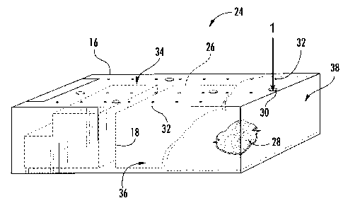
Referring to Fig. 4, a point "1" of initial injection for an expandable foam
material 28 is
indicated at the fill hole 30 closest to one longitudinal end of the cabinet
24, in this
CA 02773958 2012-04-05
249457-1
example closest to the top panel section 38. It should be appreciated that an
"end" also
encompasses a side panel section 36. This particular vent hole 30 is located
at a position
such that the foam injected through the hole migrates into the internal cavity
26 along the
top panel section 38, as well as partially onto the top panel section 34 and
partially along
the side panel section 36, as particularly illustrated by the phantom lines in
Fig. 4. In
other words, although there may be a primary target section for any individual
fill hole
30, the foam injected into such hole may overlap into another section. As the
foam
material is injected into the fill hole 30, air from the internal cavity 26 is
forced out in
vent holes 32 or towards other un-filled sections of the internal cavity 26.
A measured quantity of the foam material 28 is injected into the fill hole 30
to achieve a
desired thermal characteristic along the defined section of the cabinet 24.
For example,
the top panel section 38 is the top of the fresh food compartment 12 (Fig. 1).
It may be
desired that this particular section 38 of the cabinet 24 have a thermal
insulation
characteristic that may be different from the side panel sections 36 along the
fresh food
compartment, or side panel sections 36 along the freezer compartment 14, and
so forth.
Thus, the amount or viscosity of the foam material 28 injected into the first
fill hole 30
may have certain characteristics tailored to achieve the desired thermal
characteristics
along the particular section 38.
The distinct measured quantities of foam material 28 are injected into the
fill holes 30 in
a sequential manner starting at one end of the cabinet and working towards the
opposite
end of the cabinet 24. For example, referring to Fig. 5, the second point of
injection "2"
of the foam material 28 is indicated at the fill hole 30 that is strategically
located to
provide uniform foam distribution essentially along the remaining portion of
the top
panel section 34 for the fresh food compartment. As can be appreciated from
Fig. 5, the
measured amount of foam material 28 injected into this second fill hole 30
results in the
foam material migrating directing against the previously deposited section of
foam in one
direction, and migrating along the back panel section 34 in the opposite
longitudinal
direction. Any air within the internal cavity 26 that is displaced by
injection of the foam
6
CA 02773958 2012-04-05
249457-1
28 vents through any one or combination of the vent holes 30 or is driven
towards the
opposite longitudinal end of the cabinet 24.
Fig. 6 depicts a next sequential step wherein a third fill hole 30 is injected
with the foam
material 28. This hole 30 is strategically located so as to uniformly
distribute the foam
material 28 along the remaining portions of the side panel section 36. As
previously
mentioned, the density of the foam material 28 along this section may be
different than
the density of the foam deposited along the back panel section 34 or the
bottom panel
section 38. The viscosity of the foam may be regulated to achieve the overall
uniform
density of the foam material 28 along this section, which may be different
from the
density of the foam in other sections.
The third fill hole 30 in Fig. 6 is also located so as to distribute the foam
within the
internal rib 42 of the cabinet 24. This rib 42 is the component that separates
the freezer
compartment 14 from the fresh food compartment 12 (Fig. 1). Again, the density
of the
foam 28 within this rib 42 may be different from other sections of the foam
28.
Fig. 7 depicts the next sequential step wherein a fourth fill hole 30 is
injected with the
foam 28 in order to fill any remaining section of the internal rib 42, as well
as the
opposite side panel section 36. The third and fourth fill holes 30 also serve
to distribute
the foam 28 along a section of the back panel section 34, as depicted in Fig.
7 by the
phantom lines.
Fig. 8 depicts a next sequential step wherein a fifth fill hole 30 is injected
with the foam
material 28. This hole is strategically located to uniformly distribute the
foam 28 along a
section of the back panel 34 adjacent to the freezer compartment, as well as
along the
bottom panel section 40. It may be desired that the density of the foam in
this area is
greater than, for example, the density of the foam at the opposite top panel
section 38.
It should be appreciated from the figures, that the identified "sections" of
the cabinet 24
need not be well-defined. For example, it is difficult to control the
migration of the foam
28 within the internal cavity spaces 26 without an inordinate amount of fill
holes 30.
7
CA 02773958 2012-04-05
249457-1
However, the fill holes 30 can be strategically located so as to inject the
foam material
such that the foam migrates generally to an identified section of the cabinet,
for example
primarily along the top panel section, bottom panel section, and so forth. The
holes may
also serve to deposit the foam material 28 along different sections
simultaneously. For
example, as discussed above with respect to the third and fourth fill holes 30
in Figs. 6
and 7 wherein the foam material migrates into the internal rib 42, as well as
along a
portion of the side panel sections 36.
The amount of foam material to be injected into each of the identified
sections of the
cabinet 24 may be determined in various ways. For example, the amount and
viscosity of
the foam material may be empirically determined based on a trial and error
method
wherein numerous cabinets 24 for a given refrigerator design are injected,
allowed to
solidify, and then cut open to record the results of the injection process.
In another embodiment, the amount and viscosity of the foam material for the
different
identified sections may be determined by computer modeling, or calculations
based on
the known dimensions of the various internal cavity spaces 26.
The sequential injecting steps may be performed so that the previously
injected amount of
foam material does not significantly solidify before the adjacent section of
the cabinet is
injected with foam material. This may be done to prevent the formation of
voids or air
pockets between the adjacent sections of foam material 28. Some degree of
"skinning"
may be acceptable between the adjacent foam sections without significant
solidification
of one section prior to injection of the next adjacent section.
It should be appreciated that the invention is not limited to any particular
number and
configuration of fill holes 30. The location and number of holes 30 will
depend on the
design and structure of the particular refrigerator cabinet 24, as well as the
desired
thermal characteristics for the various cabinet sections. In this regard,
Figs. 9 through 11
depict different patterns of fill holes 30 that may be utilized. For example,
Fig. 9 depicts
a linear progression of fill holes 30 in a relatively straight line along the
back panel
8
CA 02773958 2012-09-14
249457-1
section 34. The first fill hole 30 would be used to inject foam along the top
panel section
38 and a portion of the back panel section 34 and side panel sections 36. The
injection
process proceeds from one longitudinal or side end of the cabinet 24 towards
the opposite
longitudinal or side end, as depicted by the arrows in Fig. 9. The next
sequential fill hole
30 would result in application of the foam material along an adjacent section
of the top
panel section 34 and side panel sections 36, and so forth.
In the embodiment of Fig. 10, the first fill hole 30 would result in
application of the foam
material along the top panel section 38, side panel sections 36, and a portion
of the back
panel section 34. The next subsequent fill holes 30 in the longitudinal
direction indicated
by the arrows would primarily apply the foam material along the side panel
sections 36
and a portion of the back panel section 34, wherein the combination of these
two holes 30
would result in merger of the foam material along the back panel section 34.
The
remaining fill holes 30 would be used to apply the foam material along the
internal rib
section 42 of the cabinet 24, the remaining portions of the back panel section
34, the
remaining portion of the side panel sections 36, and the bottom panel section
40.
In the embodiment of Fig. 11, the fill holes 30 are located so as to primarily
fill the side
sections 36 and the top and bottom panel sections 38, 40. The back panel
section 34
would be filled by the combined partial sections resulting from the injection
application
of the fill holes in the direction indicated in Fig. 11.
This written description uses examples to disclose the invention, including
the best mode,
and also to enable any person skilled in the art to practice the invention,
including making
and using any devices or systems and performing any incorporated methods. The
patentable scope of the invention is defined by the claims, and may include
other
examples that occur to those skilled in the art in view of the written
description.
9