Note: Descriptions are shown in the official language in which they were submitted.
CA 02774102 2012-03-13
WO 2011/038145 PCT/US2010/050041
-1-
FOLDABLE BUILDING UNITS
RELATED APPLICATIONS
This application claims the benefit of U.S. Provisional Application No.
61/245,162 , filed September 23, 2009, U.S. Provisional Application No.
61/371,524
filed August 6, 2010, U.S. Provisional Application No. 61/371,540, filed
August 6,
2010 and U.S. Provisional Application No. 61/371,513, filed August 6, 2010.
The
entire teachings of the above applications are incorporated herein by
reference.
BACKGROUND OF THE INVENTION
Architectural structures, particularly residential buildings, are typically
built
on-site with each stage of the building process requiring to transport
necessary
materials and specific skilled labor to the site. The inherent cost
inefficiency of this
approach is well known in the art.
Thus, alternative approaches have been described aimed at providing
economically priced housing. Some of these alternatives included
prefabricating
various parts of a building at a central facility, transporting the parts to a
building
site and then completing the assembly on-site. Other alternatives included
prefabricating foldable building units at a central facility, transporting the
foldable
building units to a building site, unloading and unfolding the foldable
building units
on-site using cranes, and then completing the assembly on-site.
However, it has been described that for a number of reasons, the installation
cost of prefabricated non-foldable building units was substantial and, when
added to
the cost of manufacture and delivery, caused the total cost of these
prefabricated
non-foldable building units to rise to levels detrimental for competition with
conventional construction. Previously described foldable building units have
one or
more of the following disadvantages. They require substantial work at the
building
site, substantial time for finishing at the building site, they are difficult
to
prefabricate, they do not allow precise unfolding and finishing at the
building site,
and they require cranes for unloading and unfolding at the building site.
Cranes can
be very expensive to employ, difficult to schedule, and are not even suitable
for a
CA 02774102 2012-03-13
WO 2011/038145 PCT/US2010/050041
-2-
significant percentage of building sites, thus, excluding these building sites
for a
substantial number of prefabricated foldable building units and often
requiring home
owners or developers of respective building sites to use conventional
construction.
There is, therefore, a need for foldable building units that cost less, allow
improved precision at the building site, are easier to prefabricate,
transport, and
unfold and finish quickly at the building site, and can be placed at building
sites that
were previously not suitable for placement of prefabricated foldable building
units.
SUMMARY OF THE INVENTION
One embodiment of the present invention is a foldable building unit. The
foldable building unit includes a structural frame that at least in part is
made of
frame elements that are foldably connected with metal hinges. It further
includes
interior finish materials with indirect connection to the frame elements to
reduce
direct contact of the interior finish materials with the frame elements. The
frame
elements are at least in part made of metal and the metal hinges are attached
to a
metal part of the frame elements.
Another embodiment of the present invention is a foldable building unit that
includes a structural frame that at least in part is made of frame elements
that are
foldably connected with offset hinges. The offset hinges are attached to metal
parts
of the frame elements and the offset hinges are adapted and positioned on the
frame
elements such that when folded, interior finish materials connected to the
frame
elements are offset from each other.
Another embodiment of the present invention is a foldable building unit that
includes a structural frame that at least in part is made of frame elements
that are
foldably connected with metal hinges, wherein the frame elements are at least
in part
made of metal, the metal hinges are attached to a metal part of the frame
elements,
and the metal hinges are adapted and positioned to remain within the building
unit in
unfolded configuration and finished condition.
Another embodiment of the present invention is a foldable building that
includes foldably connected finished wall panels, foldably connected finished
floor
panels, and foldably connected finished ceiling and/or roof panels. The
foldable
building in unfolded configuration is substantially in finished condition.
CA 02774102 2012-03-13
WO 2011/038145 PCT/US2010/050041
-3-
Another embodiment of the present invention is a foldable building having a
structural frame adapted to be connected to ground-level lifting rigs to lift
or lower
the foldable building.
Another embodiment of the present invention is a method for unloading a
foldable building unit from a transport vehicle. The method includes (a)
placing
ground-level lifting rigs next to the transport vehicle in positions adapted
to allow
attaching lifting members of the ground-level lifting rigs to the foldable
building
unit and to allow lifting of the foldable building unit; (b) attaching lifting
members
of the lifting rigs to the foldable building unit; (c) operating the lifting
rigs to lift the
foldable housing module off the transport vehicle; and (d) driving the
transport
vehicle to a location to remove the loading area of the transport vehicle from
underneath the foldable housing module.
Another embodiment of the present invention is a method for unfolding a
folded building unit. The method includes unfolding folded frame elements that
are
part of a structural frame of the folded building unit from a folded
configuration to
an unfolded configuration using one or more of a cable mechanism, hydraulic
mechanism or air actuation mechanism.
Another embodiment of the present invention is a foldable building
comprising a core structure made of first frame elements in fixed connection,
and
second frame elements hingedly connected, directly or indirectly, to the core
structure. The second frame elements are made of metal members, and the core
structure and the second frame elements are part of the structural frame of
the
foldable building.
Another embodiment of the present invention is a foldable building unit
comprising (a) a structural frame that at least in part is made of frame
elements that
are foldably connected with offset hinges, and (b) interior finish materials
with
indirect connection to the frame elements to reduce contact of the interior
finish
materials with the frame elements, wherein the frame elements are at least in
part
made of metal, the offset hinges are attached to a metal part of the frame
elements,
and the offset hinges are adapted and positioned on the frame elements such
that
when folded, interior finish materials connected to the frame elements are
offset
from each other.
CA 02774102 2012-03-13
WO 2011/038145 PCT/US2010/050041
-4-
Another embodiment of the present invention is a foldable building unit
comprising (a) a structural frame that at least in part is made of frame
elements that
are foldably connected with metal hinges, and (b) interior finish materials
with
indirect connection to the frame elements to reduce contact of the interior
finish
materials with the frame elements, wherein the frame elements are at least in
part
made of metal, the metal hinges are attached to a metal part of the frame
elements,
and the metal hinges are adapted and positioned to remain within the building
unit in
unfolded configuration and finished condition.
Another embodiment of the present invention is a foldable building unit
comprising (a) a structural frame that at least in part is made of frame
elements that
are foldably connected with offset hinges, and (b) interior finish materials
with
indirect connection to the frame elements to reduce contact of the interior
finish
materials with the frame elements, wherein the frame elements are at least in
part
made of metal, the offset hinges are attached to a metal part of the frame
elements,
the offset hinges are adapted and positioned on the frame elements such that
when
folded, interior finish materials connected to the frame elements are offset
from each
other, and the offset hinges are metal hinges adapted and positioned to remain
within
the building unit in unfolded configuration and finished condition.
Another embodiment of the present invention a foldable building comprising
(a) a core structure made of first frame elements in fixed connection, (b)
second
frame elements hingedly connected, directly or indirectly, to the core
structure,
wherein the second frame elements are made of metal members, and the core
structure and the second frame elements are part of the structural frame of
the
foldable building; and (c) interior finish materials with indirect connection
to the
second frame elements to reduce direct contact of the interior finish
materials with
the frame elements, wherein one or more of the second frame elements are
hingedly
connected with offset hinges attached to the frame elements, and the offset
hinges
are adapted and positioned on the frame elements such that when folded,
interior
finish materials connected to the frame elements are offset from each other.
Another embodiment of the present invention is a foldable building
comprising (a) a core structure made of first frame elements in fixed
connection, (b)
second frame elements hingedly connected, directly or indirectly, to the core
CA 02774102 2012-03-13
WO 2011/038145 PCT/US2010/050041
-5-
structure, wherein the second frame elements are made of metal members, and
the
core structure and the second frame elements are part of the structural frame
of the
foldable building; and (c) interior finish materials with indirect connection
to the
second frame elements to reduce direct contact of the interior finish
materials with
the frame elements, wherein one or more of the second frame elements are
hingedly
connected with metal hinges attached to the frame elements, and the metal
hinges
are adapted and positioned to remain within the building unit in unfolded
configuration and finished condition.
Another embodiment of the present invention is a foldable building
comprising (a) a core structure made of first frame elements in fixed
connection, (b)
second frame elements hingedly connected, directly or indirectly, to the core
structure, wherein the second frame elements are made of metal members, and
the
core structure and the second frame elements are part of the structural frame
of the
foldable building; and (c) interior finish materials with indirect connection
to the
second frame elements to reduce direct contact of the interior finish
materials with
the frame elements, wherein one or more of the second frame elements are
hingedly
connected with offset hinges attached to the frame elements, and the offset
hinges
are adapted and positioned on the frame elements such that when folded,
interior
finish materials connected to the frame elements are offset from each other,
and the
offset hinges are adapted and positioned to remain within the building unit in
unfolded configuration and finished condition.
Another embodiment of the present invention comprises a combination of
two or more, including all, of the above embodiments.
The foldable building units of the present invention have one or more of the
following advantages. They are more easily prefabricated, allow more
flexibility in
building shapes including higher ceilings and larger spaces, reduce or
eliminate
material damage due to, for example, shipment, structural deflection, thermal
flexure
and contraction, and structural aging, more easily transportable to building
sites
without requiring special permits, unloadable and unfoldable at the building
sites
often without using cranes (they can be unloaded using ground-level lifting
rigs and
unfolded using, for example, a cable mechanism) and allow significant
reduction
CA 02774102 2012-03-13
WO 2011/038145 PCT/US2010/050041
-6-
and increased speed of work to be completed on-site, where typically costs and
scheduling are far less manageable.
Additionally, as mentioned above, the methods for unloading and unfolding
foldable building units of the present invention can obviate the need for
cranes that
can be expensive and project-complicating, thereby opening up a significant
percentage of building sites for placement of prefabricated foldable building
units.
BRIEF DESCRIPTION OF THE DRAWINGS
The foregoing will be apparent from the following more particular
description of example embodiments of the invention, as illustrated in the
accompanying drawings in which like reference characters refer to the same
parts
throughout the different views. The drawings are not necessarily to scale,
emphasis
instead being placed upon illustrating embodiments of the present invention.
FIG. 1 is a perspective view of a foldable building in unfolded configuration
without interior and exterior finishing.
FIG. 2 is a perspective view of a foldable building in unfolded configuration
without interior and exterior finishing.
FIG. 3 is a perspective view of the foldable structural frame of the foldable
building shown in FIG. 1 in unfolded configuration, and further provides
detail
views of some of the structural features of the structural frame.
FIG. 4 is a perspective view of an unfolding sequence of the foldable
structural frame of the foldable building of FIG. 1 from the folded
configuration on
the left-hand side to the unfolded configuration on the right-hand side.
FIG. 5 is a perspective view of a frame element made of four hollow
structural steel sections and intermediate elements attached to the frame
element.
FIG. 6 is a cross-sectional view illustrating a powder actuated fastener
connection of a lumber sill to the hollow structural steel section of FIG. 5.
FIG. 7 is a perspective view of a finished wall panel or section.
FIG. 8 is a cross-sectional view illustrating indirect connection of interior
finish materials with a respective frame element.
FIG. 9 provides a perspective view of four folding configurations of a three-
axis step-out hinge.
CA 02774102 2012-03-13
WO 2011/038145 PCT/US2010/050041
-7-
FIG. 10 provides a front (at top of figure) and top view (at bottom of figure)
of two frame elements that are foldably connected with a three-axis step-out
hinge.
FIG. 11 is a top view of the hinge area of the two foldably connected frame
elements shown in FIG. 10 for four folding configurations.
FIG. 12 is a perspective view of a fixed-axis offset hinge.
FIG. 13 is a cross-sectional view of two foldably connected hollow structural
steel sections in which the seam or fold between the hollow structural steel
sections
as well as the hinge(s) are covered with a flexible polymer gasket.
FIG. 14 is a cross-sectional view of part of a finished wall panel or section.
FIG. 15 is a perspective view of four ground-level lifting rigs holding the
folded structural frame of a foldable building.
FIG. 16 is a perspective view illustrating steps of the uploading (from left
to
right) or unloading (from right to left) of a foldable building unit on a
transport
vehicle.
FIG. 17 is a perspective view of an unfolding sequence of the foldable
structural frame of the foldable building of FIG. 2 from the folded
configuration on
the left-hand side to an unfolded configuration on the right-hand side.
FIG. 18 is a cross-sectional view of a folding wall corner in unfolded
configuration and substantially finished condition.
FIG. 19 is a cross-sectional view of the folding wall corner of FIG. 18 in
finished condition.
FIG. 20 illustrates the use of a cable mechanism in unfolding and folding of
a foldable floor section of a foldable building unit.
FIG. 21 is a cross-sectional view of a hinged wall detail in unfolded
configuration and substantially finished condition.
FIG. 22 is a cross-sectional view of the hinged wall detail of FIG. 21 in
finished condition.
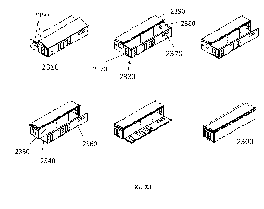
FIG. 23 is a perspective view of an unfolding sequence of one embodiment
of a clerestory-shaped single-story foldable building of the present invention
FIG. 24 is a cross-sectional view of a fixed-axis offset hinge in an unfolded
configuration with each hinge leave attached to a structural member.
DETAILED DESCRIPTION OF THE INVENTION
CA 02774102 2012-03-13
WO 2011/038145 PCT/US2010/050041
-8-
A description of example embodiments of the invention follows.
Although the teachings of the present invention are applicable to a wide
variety of structures of different weight, size, shape and materials for a
variety of
diverse uses, for purposes of the following description, the present invention
will be
described in the context of prefabricated foldable building units.
The foldable buildings (and, more generally, foldable building units) of the
present invention can be prefabricated such that the foldable buildings, after
unfolding on the building site, are substantially in finished condition. That
is, they
do not require or significantly reduce the addition of further building
sections such
as wall panels, floor and roof sections, or the addition of interior and
exterior finish
materials with the exception of minor, non-structural finishing in areas
required for
folding movement. However, the prefabrication process can be reduced
substantially, even to the extent that merely a foldable structural frame of
the present
invention is prefabricated and unfolded at the building site.
Further, all necessary mechanical and electrical systems for the residential
or
commercial foldable building, for example, , all the required appliances and
plumbing fixtures, can be installed in a core structure (i.e., a part of the
structural
frame of the foldable building that is made of frame elements that are not
unfolded
at the building site, typically, frame elements that share at least one fixed
seam
connection with another frame element) of the foldable building at the time of
its
prefabrication. At this point, the foldable building has been brought into
finished
condition and only requires connection to the local utilities, e.g.
electricity and
sewerage, and seam connections for it to be completed.
FIG. 1 is a perspective view of a foldable building 100 in unfolded
configuration without interior and exterior finishing. The foldable building
contains
a structural frame that includes interconnected frame elements 110 made of
hollow
structural steel sections and wooden intermediate elements 120 attached
thereto.
Selected frame elements are foldably connected with hinges 130 that can be of
various designs described herein. For ease of illustration, interior and
exterior
finishing materials are not shown. Such materials are preferably attached
(e.g.,
glued, nailed, screwed, welded and/or bolted, or otherwise fastened) to the
intermediate elements 120.
CA 02774102 2012-03-13
WO 2011/038145 PCT/US2010/050041
-9-
Use of appropriately dimensioned metal sections, more typically, hollow
structural steel sections as shown in FIG. 1, as part of a foldable structural
frame of a
foldable building unit, and, particularly, foldably connected frame elements
made of
hollow structural steel sections, have been found to be advantageous for a
number of
reasons including the following: Fewer and/or smaller hinges (typically, metal
hinges) can be used to foldably connect frame elements, reducing labor and
material
cost in the prefabrication process, reducing the cost of on-site finishing,
and
increasing the precision of the folding and unfolding of foldably connected
frame
elements thereby further reducing the labor and material cost of on-site
finishing by
enabling prefabrication of interior and exterior materials that fit into the
unfinished
areas (e.g., seams of foldably connected frame elements) after unfolding (see,
e.g.,
FIGS. 18 and 19 with regard to finishing material that is desired and can be
prefabricated to complete a typical folding wall corner with minimal on-site
labor).
Large frame geometries as part of the structural frame, for example,
rectangular
frame elements spanning the entire side of a foldable building can be employed
(see,
e.g., the wall frame element 450 in FIG. 4), reducing prefabrication cost
and/or
simplifying the unfolding.
Further, foldable structural frames substantially made of metal frame
elements (e.g., made from hot-formed steel, for example, from hollow
structural
steel sections) can be prefabricated to superior tolerances such that a
respective
foldable building unit in substantially finished condition upon unfolding
exhibits
reduced or no gaps in the seam areas between foldably connected frame elements
thereby reducing the work associated with on-site finishing of these seam
areas.
FIG. 2 is a perspective view of a further foldable building 200 in unfolded
configuration without interior and exterior finishing. The foldable building
contains
a structural frame that includes interconnected frame elements 110 made of
hollow
structural steel sections and wooden intermediate elements 120 for attachment
of
finish materials (not shown). Selected frame elements are foldably connected
with
hinges 130. The foldable building includes frame elements that are unfolded
during
unfolding and others that remain fixed. The roof of the foldable building
includes a
fixed roof section 210 and a foldable roof section 215 which is foldably
connected
with hinges 130 to the fixed roof section 210. The floor of the foldable
building
CA 02774102 2012-03-13
WO 2011/038145 PCT/US2010/050041
-10-
includes a fixed floor section 220 foldably connected to a foldable floor
section 225.
Further, the fixed roof section 210 and fixed floor section 220 are in fixed
connection with fixed wall sections 230, 232 and 234. Fixed wall section 232
is
foldably connected with the foldable wall section 240 which itself is further
foldably
connected to foldable wall section 242. Fixed wall section 234 is foldably
connected with the foldable wall section 244 which itself is further foldably
connected to foldable wall section 246. Foldably connected sections are
connected
with hinges (not all hinges shown) attached to the frame elements of the
respective
sections.
Foldable building units, for example, the foldable buildings shown in FIGS.
1 and 2, can further include a number of prefabricated interior walls (not
shown) that
can be fixed, foldably connected, or panelized and form one or more rooms in
the
unfolded building.
The foldable buildings of the present invention can be several stories high.
With the use of a crane, multi-story structures can be built on-site by
stacking
separate foldable building units with a crane. In this arrangement, ceiling
frame
elements of the lower unfolded foldable building unit lie directly below floor
frame
elements of the upper foldable building unit. During prefabrication,
appropriate
openings can be included in the ceiling of the lower foldable building unit
and in the
floor of the upper foldable structure to accommodate a staircase, which can be
installed in the lower foldable building unit during prefabrication.
FIG. 3 is a perspective view of the foldable structural frame of the foldable
building shown in FIG. 1 in unfolded configuration, including detail views of
some
of the structural features of the structural frame.
FIG. 4 is a perspective view of an unfolding sequence of the foldable
structural frame of the foldable building of FIG. 1 from the folded
configuration 400
on the left-hand side to the unfolded configuration 300 on the right-hand
side. The
unfolding sequence is shown for the foldable structural frame; however, the
same
unfolding sequence can be used for a respective substantially finished
foldable
building. The roof frame elements 410 and 420, and the clerestory truss frame
element 430 are lifted (e.g, with a cable mechanism) to provide unfolding
space for
the floor frame element 440 which is foldably connected to the wall frame
element
CA 02774102 2012-03-13
WO 2011/038145 PCT/US2010/050041
-11-
450. Floor frame element 440 is folded downward to the ground and wall frame
element 450 upward to establish a wall (e.g., front wall) of the foldable
building,
Then, the roof frame elements 410 and 420 can be lowered onto and connected to
the wall frame element 450, followed by the unfolding of the wall frame
elements
460, 470 and 480 (note that wall frame element 480 is foldably connected and
part
of the structural frame 400 but only shown in for the foldable building in
unfolded
configuration 300). It is to be understood, that the above unfolding sequence
is not
the only possible sequence for unfolding the foldable building 400. For
example,
the wall frame elements 460 and 470 could be unfolded, at least partly, prior
to
unfolding or completing the unfolding of roof frame elements 410 and 420. The
core structure of the structural frame is provided by the frame elements that
are not
moved during unfolding to the unfolded configuration 300.
Foldable building units of the present invention can unfold from one side of
a core structure of the structural frame of the foldable building unit as
shown, for
example, in FIG. 4, but can also be designed to unfold from a plurality of
sides. For
example, a foldable building of the present invention can be adapted to unfold
in
two opposite directions.
FIG. 5 is a perspective view of an unfinished wall section or panel 500 that
includes a frame element made of four structural steel sections 510 and
intermediate
elements attached to the frame element. The intermediate elements are a lumber
sill
520 (i.e., a wooden bottom plate element) and a lumber header 530 (i.e., a
wooden
top plate element), both fastened to the frame elements with powder actuated
fasteners or other suitable fasteners 540 (fasteners connecting the lumber
header 530
to the frame element are not visible in this perspective view). Lumber studs
550
(i.e., stud elements) are fastened between the lumber header 530 and the
lumber sill
520. Interior finish materials can be attached (e.g. nailed, screwed, fastened
and/or
glued) to the intermediate elements (here, lumber) to connect indirectly to
the frame
element.
Steel frame elements can be combined with wooden intermediate elements as
shown in FIG. 5 to form lightweight steel and wood hybrid structures in which
the
frame elements provide structural stability and the wooden intermediate
elements
provide substantial lateral structural resistance and are used to attach
interior and
CA 02774102 2012-03-13
WO 2011/038145 PCT/US2010/050041
-12-
exterior finishing material using standard construction approaches, reducing
labor
training and associated costs. Use of these strong and lightweight structures
(and, in
particular, the use of the foldable structural frames of the present
invention)
substantially reduces the amount of required building material, and also
allows
reduced weight of the frame elements and, thus, reduced weight of the foldable
building unit, which in turn facilitates the transport of larger folded
building units
for a given maximal allowed weight according to given road regulations.
Further, a
reduced weight of foldably connected frame elements can facilitate the
unfolding of
these frame elements without the use of a crane.
FIG. 6 is a cross-sectional view illustrating a powder actuated fastener or
other suitable fastener connection of the lumber sill 520 to the structural
steel
section 510 of FIG. 5. The lumber sill 520 is positioned and dimensioned to
provide
a wood offset 610 from the steel of the hollow structural steel section 510.
The
wood offset 610 can reduce or prevent contact of interior finish material (not
shown;
e.g. drywall attached to the lumber sill 520) with the steel. It can also
reduce heat
transfer and/or reduce or prevent contact of potential condensate formed on
the steel
with interior finish material.
It has been found that the use of powder actuated fasteners allows
establishment ofa strong connection between wooden intermediate elements and
steel frame elements (in particular, made of hollow structural steel sections)
quickly,
reducing the prefabrication cost and providing significant connection
strength.
FIG. 7 is a perspective view of a finished wall panel or section 700, which
can be obtained by attaching interior finish material, such as gypsum wall
board 710
and a baseboard 720, to an unfinished wall panel. The finished wall panel 700
includes interior finish material, such as gypsum wall board 710 and a
baseboard
720, with indirect connection to the respective frame element. The indirect
connection is further illustrated in FIG. 8.
FIG. 8 is a cross-sectional view illustrating indirect connection of interior
finish materials with a respective frame element. Interior finish material,
such as a
gypsum wall board 710, is attached to a bottom plate (here, a wood sill plate
520)
which in turn is fastened using a powder actuated fastener or other suitable
fastener
540 to the hollow structural steel section 510. A baseboard 720 is attached to
the
CA 02774102 2012-03-13
WO 2011/038145 PCT/US2010/050041
- 13 -
gypsum wall board 710 and optionally a plywood backer board 810 fills the wood
offset gap.
The indirect connection shown in FIG. 8 is one of a number of possible
connections that allow reduction of structural stress transfer from the
structural
frame to interior finishing materials, reduce heat loss, and improve moisture
control.
A further indirect connection is shown in FIGS. 18 and 19.
Indirect connections of interior and/or exterior finishing materials to metal
frame elements (particularly, frame elements made of structural steel
sections) are
one aspect of a "multi-tolerance" building approach that disaggregates and
cushions
brittle or otherwise fragile finish materials from the vibrational, kinetic
and settling
forces applied to the structural frame during shipping, setting, unfolding and
settling
of the prefabricated foldable building units. A second aspect of a multi-
tolerance
building approach is provided by the offset hinges of the present invention
which are
specifically engineered to safely nest hingedly (i.e., foldably connected with
one or
more hinges) connected frame elements at a designed distance away from its
neighboring frame element, allowing, for example, for thicker wall depths and
thus
the prefabricated inclusion of finish materials. This is associated with a
significant
reduction in the scope of work to be completed on-site, where costs and
scheduling
are far less manageable. Thus, foldable building units of the present
invention can
include final interior finishing, such as trim, gypsum board, paint or
wallpaper.
FIG. 9 is a perspective view of four folding configurations of a three-axis
step-out hinge 900 (e.g., a type of offset hinge). Hinge leaves 910 extend
into hinge
knuckles 920 surrounding hinge pins 930. Center hinge leaves 940 extend in two
directions into hinge knuckles 920 surrounding hinge pins 930. The folding
configurations can be part of a folding and/or unfolding sequence.
The three-axis step-out hinges provide folding flexibility and can increase
the packing/folding degree of a foldable building unit.
FIG. 10 provides a front view (at top of figure) and top view (at bottom of
figure) of two frame elements 110 that are foldably connected with a three-
axis step-
out hinge 900.
FIG. 11 is a top view of the hinge area of the two foldably connected frame
elements 110 shown in FIG. 10, providing four folding configurations that can
be
CA 02774102 2012-03-13
WO 2011/038145 PCT/US2010/050041
-14-
part of an unfolding sequence from an unfolded configuration (for example, the
folding configuration shown on the left-hand side) to the folded configuration
shown
on the right-hand side. One of the frame elements 110 is connected to one of
the
hinge leaves 910 of the three-axis step-out hinge through a spacer element
1110
dimensioned and positioned such that a planar surface is jointly formed by the
two
foldably connected frame elements in the unfolded configuration shown on the
left-
hand side of the figure. As can be seen for the folded configuration, a three-
axis
step-out hinge can provide an offset 1120. Thus, interior finish materials
(not
shown) attached to the frame elements can be offset from each other.
FIG. 12 is a perspective view of a fixed-axis offset hinge. Hinge leaves 910
with extended hinge knuckles 1210 surrounding a hinge pin 930 can be rotated
around the axis provided by the hinge pin 930. In completely folded
configuration
(not shown) the offset hinge provides an offset which increases with the
length of
the extension 1220 of the extended hinge knuckles 1210. Thus, interior finish
materials (not shown) attached to the frame elements can be offset from each
other.
FIG. 13 is a cross-sectional view of two foldably connected hollow structural
steel sections 510 in which the seam or fold between the hollow structural
steel
sections 510 as well as the hinge(s) 1310 are covered with a flexible polymer
gasket
1320 which is attached (for example, glued) to the hollow structural steel
sections.
FIG. 14 is a cross-sectional view of part of a finished wall panel or section
illustrating indirect connection of the of interior and exterior finish
materials to a
structural steel section of a frame element. Two intermediate elements, a wood
face
plate 1410 and a wood plate 1420 (e.g., lumber sill) are attached to a
rectangular
structural steel section 1430. A wood stud 1440 is further attached to the
wood plate
1420. Interior finish material 1460 (for example, gypsum board) is attached to
the
wood plate 1420. Exterior finish material 1450 (for example, plywood or OSB
sheating) is attached to the wood face plate 1410, the wood plate 1420, and/or
the
wood stud 1440.
FIG. 15 is a perspective view of four ground-level lifting rigs 1510 holding a
folded steel assembly 1520 of a foldable building. Only the steel assembly is
shown; however, foldable building units in various finished conditions, can be
held,
lifted and lowered using ground-level lifting rigs such as the ones that are
shown.
CA 02774102 2012-03-13
WO 2011/038145 PCT/US2010/050041
- 15-
Each lifting rig 1510 includes a hoist 1530 (e.g., manual or electric) and a
lifting
member 1540 (e.g., chain with hook for connection to a solid stock steel rig).
Connection members 1550 (e.g., a solid stock steel rig) are connected to the
lifting
members 1540 of the ground-level lifting rigs 1510. Connection members can be
part of the folded steel assembly and extendable into an extended position as
shown,
or they can be separate parts that are inserted into the folded steel assembly
(e.g.,
into hollow structural steel sections of a floor frame element).
FIG. 16 is a perspective view illustrating the steps of uploading (from left
to
right) or unloading (from right to left) of a foldable building unit (here,
the folded
foldable building unit is illustrated in terms of its folded steel assembly
1520) on a
transport vehicle 1610. For uploading, the ground level lifting rigs are
placed next
to the foldable building unit (which is folded sufficiently to comply with
transport
regulations). The folded steel assembly 1520 and lifting members of the ground-
level lifting rigs are attached to the folded building unit. Then the lifting
rigs are
operated to lift the folded building unit up to a height sufficient to allow
the
transport vehicle 1610 to drive its loading area 1620 under the folded steel
assembly.
On the left, four ground-level lifting rigs 1510 are holding the folded steel
assembly
1520 at a height sufficient to allow the transport vehicle 1610 to drive its
loading
area 1620 under the folded steel assembly 1520. The transport vehicle 1610
moves
its loading area 1620 under the folded steel assembly as shown in the middle
and on
the right of the figure. After the loading area 1620 has been placed
appropriately
under the folded building unit as shown at the right, the lifting rigs can be
operated
to lower it onto the loading area. The ground-level lifting rigs can then be
disconnected, and, if desired, also transported to a building site for use in
unloading
of the foldable building unit.
FIG. 17 is a perspective view of an unfolding sequence of the foldable
structural frame of the foldable building of FIG. 2 from the folded
configuration
1700 on the left-hand side to an unfolded configuration 1710 on the right-hand
side.
The unfolding sequence is shown for the foldable structural frame; however,
the
same unfolding sequence can be used for the respective substantially finished
foldable building. First a floor 1720 and/or roof panel 1730 is unfolded, then
two
CA 02774102 2012-03-13
WO 2011/038145 PCT/US2010/050041
-16-
separate pairs of hingedly connected wall panels 1740 and 1750 are unfolded to
complete the building envelope.
FIG. 18 is a cross-sectional view of a folding wall corner in unfolded
configuration and substantially finished condition. A hinge 1810 is attached
to
members 1820 (typically, hollow structural steel sections) of two foldably
connected
frame elements. Intermediate elements 1830 (e.g., lumber) are attached to the
members 1820. Interior finish materials, such as drywalls 1840, are attached
to
intermediate elements 1830. Exterior finish materials such as sheathing 1850
(e.g.,
Advantech(V sheathing), housewrap 1860, siding 1870 (e.g. wood or corrugated
steel
siding), and plywood 1880 are directly or indirectly attached to the
intermediate
elements 1830 in a manner that leaves unfinished areas 1890 dimensioned to
accommodate folding of the frame elements.
FIG. 19 is a cross-sectional view of the folding wall corner of FIG. 18 in
finished condition. Additional interior finish material such as drywall 1910
is
attached (e.g., drywall glued and/or screwed) to the intermediate element with
tape
1920 at the seams. Further, foam 1930 and exterior finish material such as
wood
trim 1940 is added to finish the exterior unfinished area.
FIG. 20 illustrates the use of a cable mechanism in unfolding and folding of
a foldable floor section 2000 of a foldable building unit. For ease of
illustration,
merely part of a structural frame of a foldable building unit in cross-
sectional view is
provided. A cable 2010 of an electric winch 2020 (attached, for example, to a
fixed
part of the structural frame) is guided through appropriately selected frame
elements
to a position that is suitable for folding (here lifting) or unfolding (here
lowering) of
the foldable floor section 2000. If the cable is attached to the clerestory
truss, the
cable mechanism can be used to raise or lower the clerestory truss.
FIG. 21 is a cross-sectional view of a hinged wall detail 2100 in unfolded
configuration and substantially finished condition. A hinge 2110 foldably
connects
a first structural member 2120 (typically, a structural steel section) of a
first
substantially finished panel (only part of which is shown in the cross-
sectional view)
with a second structural member 2130 (typically, a structural steel section)
of a
second substantially finished panel (only part of which is shown in the cross-
sectional view). Intermediate elements 2140 and 2150 (e.g., here lumber) are
CA 02774102 2012-03-13
WO 2011/038145 PCT/US2010/050041
-17-
attached to the members 2120 and 2130, respectively. Interior finish
materials, such
as drywall 2160, are attached to the intermediate elements 2140 and 2150.
Exterior
finish materials such as sheathing 2170 (e.g., Advantech sheathing), siding
2180
(e.g. wood or corrugated steel siding), and plywood 2190 are directly or
indirectly
attached to the intermediate elements 2140 and 2150 in a manner that leaves
unfinished areas 2195 dimensioned to accommodate folding of the frame
elements.
A foldable connection between two substantially finished wall panels can
include one or more, typically, at least two hinges, that can be configured
and
positioned as shown, for example, in FIG. 21.
FIG. 22 is a cross-sectional view of the hinged wall detail of FIG. 21 in
finished condition 2200. Additional interior finish material such as foil
backed
drywall 2210 is attached (e.g., glued and/or screwed) to the intermediate
element
with tape 2220 at the seams. Further, foam 2230 and exterior finish material
such as
wood (e.g. cedar) trim 2240 is added to finish the exterior unfinished area.
The hinged wall detail of FIGs. 21 and 22 separates the structural members
from direct contact with the finish-grade materials which are more brittle and
would
tend to degrade if forces from the structural members were substantially
transferred
to them. Moreover, the hinged wall detail does not provide a direct metal
pathway
between the exterior and interior of the structure in order to prevent
undesirable
transfer of heat between the interior and exterior of the structure.
FIG. 23 is a perspective view of an unfolding sequence for one embodiment
of a clerestory-shaped single-story foldable building of the present invention
from
the folded configuration 2300 to an unfolded configuration 2310. The folded
building is very compact and properly dimensioned to allow for efficient
transport to
the building site. The unfolding sequence can be used with one or more, and,
more
typically, all of the panels (fixed and foldable connected ones) in
substantially
finished condition; even windows 2320 and doors 2330 can be part of the folded
building. Firstly, a floor panel 2340 hingedly connected to a core structure
2350 of
the foldable building is unfolded. The floor panel 2340 is further hingedly
connected to a wall panel 2360, which typically is unfolded after the floor
panel
2340 has been unfolded. Further wall panels 2370 and 2380 hingedly connected
to
the core structure are unfolded and fastened to the unfolded wall panel 2360.
Then
CA 02774102 2012-03-13
WO 2011/038145 PCT/US2010/050041
-18-
the roof panel 2390 is unfolded and fastened to one or more of the unfolded
wall
panels.
FIG. 24 is a cross-sectional view of a fixed-axis offset hinge 2410 with each
hinge leave 2420 attached to a structural member (typically, structural steel
member)
shown in an unfolded configuration. Typically, fixed-axis offset hinges such
as the
one shown in the drawing are attached to the structural members so that a
tolerance
2420 (e.g., 1/8") is provided. In completely folded configuration (not shown)
the
offset hinge provides an offset, which allows sufficient clearance for finish
and other
materials. Further, the interior finish materials (not shown) attached to the
frame
elements can be sufficiently offset from each other to avoid direct and
potentially
damaging contact, for example, during transport.
The foldable building units of the present invention can be adapted to
accommodate unfolding using a robust, cost-effective cable mechanism enabling
the
smooth and facile unfolding of prefabricated homes, on-site, without the need
for a
crane or cranes which can be expensive and project complicating.
Specifically, foldable structural frames of the present invention can include
frame elements made at least in part of materials with point load strengths
adapted
for point loading arising from pulling the respective frame elements with a
device
such as a cable hoist.
The use of ground-level rigs of the present invention can have several
advantages compared to the use of cranes for unloading foldable building units
including the following. Ground-level lifting rigs can be used for unloading
foldable building units on building sites that are not suited for the use of
cranes or
even accessible by cranes. Further, ground-level rigs can be transported along
with
the folded building unit on the transport vehicle, thus, allowing unloading at
any
desired time without advance scheduling (as is typically required if cranes
are used).
A "foldable building unit" as used to herein, is a part of a building or an
entire building, wherein the part or entire building are foldable, that is,
can be folded
from an unfolded configuration to a folded configuration and vice versa. For
example, a foldable building unit can be one or more foldable rooms of a
building, a
foldable story of a building, or an entire foldable building. Preferably, the
foldable
building unit is an entire foldable building. A foldable part of a building or
an entire
CA 02774102 2012-03-13
WO 2011/038145 PCT/US2010/050041
-19-
foldable building can be several stories high in unfolded configuration,
typically,
however, more typically, one or two stories high. A foldable building unit in
"unfolded configuration" is a foldable building unit in which the foldably
connected
frame elements have been unfolded into positions that can be maintained in the
finished condition of the foldable building unit. A foldable building unit in
"folded
configuration" is a foldable building unit in which foldably connected frame
elements are folded into positions suitable for uploading, transport, and/or
unloading
of the building unit. The foldable building or foldable building unit can be a
commercial or residential building.
The present invention also encompasses buildings that are more than two
stories high. Such buildings can be built from one unfolding building unit or
from a
plurality of foldable building units, for example, each foldable building unit
being
typically one or two stories of the final multi-story building. Typically, in
many
locations, use of a crane is not desirable due to associated cost and possible
crane
scheduling difficulties. However, if buildings with more than two stories are
to be
set up on the building site, more typically, a crane can be employed.
Foldable buildings of the present invention can have one or more rooms.
A "structural frame" as used herein, refers to the totality of members of a
foldable building unit that are primarily responsible for providing structural
stability
of the foldable building unit in folded, partially unfolded and unfolded
configuration, and which transmit loads (e.g., static, dynamic, and/or
vibrational
loads) to the ground. A structural frame of a foldable building unit can be
made at
least in part of frame elements that are foldably connected. Other parts of
the
structural frame can be connected in fixed relative positions. Typically, a
structural
frame can comprise both, foldably connected frame elements and frame elements
in
fixed relative positions. However, the structural frame can also consist
entirely of
foldably connected frame elements. Structural frames can include members that
are
made of a plurality of materials in various forms and dimensions. Suitable
materials
that can be used include but are not limited to wood, metal (e.g., aluminum or
steel)
and polymers. Suitable forms include but are not limited to I-beams, wide-
flang e
beams, angles, hollow structural sections and channel sections. The selection
of a
material, form and dimension for a given structural part or member of a
structural
CA 02774102 2012-03-13
WO 2011/038145 PCT/US2010/050041
-20-
frame is interdependent and depends on factors such as the position of the
structural
part or member in the structural frame, and whether the member is part of a
frame
element that is foldably connected.
A "frame element" as used herein, refers to an element of a structural frame
of a foldable building unit that includes a plurality of members that form a
closed or
open frame. Typically, the members form a closed frame. However, the members
can also form an open frame, or have additional members as shown attached
thereto.
Typically, frame elements that are foldably connected through hinges are made
at
least in part of metal, wherein the hinges are attached to metal parts, for
example, a
metal member, of the frame elements. Frame elements can include one or more
members made of metal, typically, at least the member to which a hinge is
attached
is made of metal. Suitable metals include but are not limited to aluminum and
steel.
Preferably, the metal members are made from hot-formed steel. Suitable hot-
formed
steel includes hollow structural steel sections, I-beams and steel channels
(typically,
C-shaped cross-section). Typically, the hot-formed steel is a hollow
structural steel
section or a steel channel. Steel members can be connected, for example, by
welding to form a steel frame element.
Frame elements can include parts or have elements attached to them that
enable automatic guidance of the relative movement of foldably connected frame
elements during folding and/or unfolding.
Frame elements can further include parts or have elements attached to them
that enable automatic locking or bolting of foldably connected frame elements
in
selected folding configurations.
Interior and exterior finish materials can be attached to the structural
frame,
and, specifically, frame elements of the structural frame. Interior finish
materials
include but are not limited to wall finishing (for example, gypsum board and
Advantech sheathing), ceiling finishing and floor finishing (for example,
Advantech sheathing with Bamboo flooring on top. Exterior finishing elements
include but are not limited to siding and roofing.
For finish materials, and, in particular, interior finish materials, it has
been
found that "indirect connection" to the frame elements to reduce contact,
partially or
entirely, of the interior finish materials with the frame elements is
advantageous for
CA 02774102 2012-03-13
WO 2011/038145 PCT/US2010/050041
-21-
one or more of the following reasons. Reduced contact can (a) reduce the
transfer of
structural stresses from one or more frame elements of the structural frame to
the
often fragile and brittle interior finish materials thereby reducing or
eliminating
significant damage (such as dry wall cracking) of the interior finish
materials, in
particular, during folding, uploading, transporting, unloading and/or
unfolding of the
foldable building unit, (b) reduce or eliminate the exposure of the interior
finish
materials to water, for example, water that can condensate on metal parts of
the
frame elements, and (c) reduce heat transfer between the inside of the
finished
building unit to the outside of the finished building unit.
Thus, generally, it is preferred to use indirect rather than direct
connections
of finish materials, particularly, interior finish materials with respective
frame
elements. However, even though indirect connections are typically preferred,
not all
connections between interior finish material and a respective frame element
have to
be indirect.
Indirect connections are particularly preferable for frame elements made
entirely from metal, that is, metal frame elements. However, even though
"indirect
connections" are favorable, direct connections (e.g., glue, screws, nails
etc.) can also
be present, even to metal parts of the frame elements.
Indirect connections can be provided through intermediate elements.
Intermediate elements can be made of a plurality of materials. Preferably,
intermediate elements are made, at least in part, of materials that have a
force
cushioning effect, that is, force cushioning elements such as, for example,
wood,
sprayed foam, and light-gauge aluminum studs. Typically, an intermediate
element
is positioned and dimensioned such that it can connect or can be connected
(e.g.,
using powder-actuated fasteners or self-tapping screws) to the frame element
through one area of the intermediate element (e.g., through one side of the
intermediate element) and that it can be connected to the finish material,
particularly, the interior finish material (for example, using nails or
screws) through
another area of the intermediate element (e.g., through another side of the
intermediate element). Even more preferably, intermediate elements are
entirely
made of force cushioning materials such as wood. Foldable building units of
the
present invention can include wall panels, roof and floor sections that are in
CA 02774102 2012-03-13
WO 2011/038145 PCT/US2010/050041
-22-
substantially finished condition, that is, with the exception of unfinished
areas
dimensioned to accommodate folding of the frame elements, and unfinished areas
due to wall connection seams (i.e., seams between walls that are not connected
but
upon unfolding jointly form a wall), these wall panels, roof and floor
sections are
finished.
"Finished panels" as referred to herein, are panels that include frame
elements and interior finish materials connected (typically, indirectly) to
them, and
can also include elements such as doors and windows. Finished panels can be,
for
example, finished wall panels, finished floor panels, finished ceiling panels
and
finished roof panels.
"Metal hinges" as referred to herein, refers to hinges in which at least the
load bearing parts (including hinge leaves, hinge knuckles and hinge pin(s))
are
made of metal. Preferably, the entire hinge is made of metal. Preferably, the
metal
is steel.
"Offset hinges" as referred to herein, are hinges that include at least two
hinge leaves that are foldably connected and provide an offset between the two
hinge leaves in folded configuration. Offset hinges can include two hinge
leaves
that are foldably connected around one, two, three or more axes. An offset set
hinge
that provides for one axis of rotation is hereinafter also referred to as a
"fixed-axis
hinge." Preferably, fixed-axis hinge is made of two hinge leaves that have
extended
hinge knuckles attached thereto, wherein the extended hinge knuckles extend
around
a hinge pin to foldably connect the hinge leaves. For an offset hinge, the
extension
provided by each of the extended hinge knuckles can be of the same length or
they
can be different. Typically, the extension provided by each of the extended
hinge
knuckles of an offset hinge is the same. Extended hinge knuckles of different
extension lengths can be desired if, for example, the thicknesses of two frame
element that are to be foldably connected is different. The larger the
extensions
provided by the extended hinge knuckles of an offset hinge are, the larger can
be the
offset between interior finish materials connected (typically, indirectly) to
the frame
elements.
CA 02774102 2012-03-13
WO 2011/038145 PCT/US2010/050041
- 23 -
Typically, at least the load bearing parts (including hinge leaves, extended
hinge knuckles, and hinge pin(s)) of offset hinges are made of metal.
Preferably, the
entire offset hinge is made of metal. Preferably, the metal is steel.
An offset hinge that provides for two, three or more axes of rotation is
hereinafter also referred to as a "step-out hinge." With increasing number of
axes
that are being provided by the step-out hinge, the degrees of freedom for
folding
increase, however, at the same time controlling the folding process becomes
increasingly difficult. Preferably, step-out hinges provide for three axis of
rotation
(i.e., three-axis step-out hinge). More preferably, a step-out hinge includes
a first
hinge leaf, a second hinge leaf, a first center hinge leaf and a second hinge
leaf,
wherein the first hinge leaf is foldably connected to the first center hinge
leaf, the
first center hinge leaf is foldably connected to the second center hinge leaf,
and the
second center hinge leaf is foldably connected to the second hinge leaf. It
has been
found that step-out hinges with a plurality of axes provide advantageous
folding
flexibility relative to single axis hinges. Typically, at least the load
bearing parts
(including hinge leaves, extended hinge knuckles, and hinge pin(s)) of step-
out
hinges are made of metal. Preferably, the entire step-out hinge is made of
metal.
Suitable metals include steel. Hinges can be attached via their respective
hinge
leaves to frame elements to foldably connect the frame elements. In the
preferred
case of metal hinges that are to be attached to metal parts of frame elements,
for
example, metal members or entire metal frame elements, the hinges can be
attached,
for example, by welding. Typically, hinge leaves of metal hinges are welded to
frame elements using methods known in the art.
Hinges and, in particular, offset hinges and step-out hinges (which can also
be offset hinges) allow for a plurality of folding configurations associated
with
respective relative positions of the hinge leaves and respective attached
frame
elements. Typically, the step-out hinges suitable in the present invention
provide an
offset. For example, FIG. 9 provides a perspective view of four folding
configurations of a three-axis step-out hinge providing an offset in the
folded
configuration. Typically, for a three-axis step-out hinge the folded
configuration is
as shown at the bottom of FIG. 9. If interior finish materials are connected
(typically, indirectly) to the frame elements such that they face each other
in the
CA 02774102 2012-03-13
WO 2011/038145 PCT/US2010/050041
-24-
folded configuration, the three-axis step-out hinge provides an offset in the
folded
configuration, that is, it offsets the interior finish materials from each
other. If the
hinge is used to foldably connect two frame elements that jointly form a flat
surface,
for example, a floor in the finished building unit, the folding configuration
as shown
at the top can correspond to the unfolded configuration. If the hinge is used
to
foldably connect two frame elements that jointly form, for example, a 90
degrees
wall corner in the finished building unit, the third folding configuration
from the top
shown in FIG. 9 can correspond to the unfolded configuration. If the two
foldably
connected frame elements are desired to be placed at different angles in the
finished
building unit, other folding configurations of the three-axis step-out hinge
can
correspond to the unfolded configuration.
Hinges and/or frame elements can further include spacer elements (see, e.g.,
Feature 1110 in FIG. 11) that are sandwiched between the hinge leaves and
frame
elements such that a desired unfolded configuration of the foldably connected
frame
elements is achieved. In addition or alternatively, hinge leaves, parts of a
member
of a frame elements, members of a frame element or entire frame elements can
have
different dimensioned to achieve a jointly formed planar surface.
The hinges used in the foldable building units of the present invention can be
adapted and positioned to remain within the building unit in unfolded
configuration
and finished condition.
A spacer element can be part of the three-axis step-out hinge, in particular,
one of the hinge leaves of the three-axis step-out hinge can have a thickness
that
obviates the spacer element. The spacer element can also be part of the frame
element, for example, the frame element may have a thickness in the area to
which
the hinge leave is to be attached that obviates the need for a spacer element.
Alternatively, the spacer element can be a separate element that can be
attached to
the hinge leave and frame element. Typically, a spacer element is made of
metal,
preferably, of steel.
For foldable building units that are pre-fabricated to include interior finish
material, it is desirable that the foldable building unit in folded
configuration can be
uploaded, transported and unloaded without significant direct contact of
finish
materials of the folded panels. It has been found that contact can be reduced
or
CA 02774102 2012-03-13
WO 2011/038145 PCT/US2010/050041
-25-
entirely prevented by using appropriately dimensioned offset hinges to
foldably
connect frame elements that have interior finish materials attached to them.
The foldable building units of the present invention can be unfolded on a
building site to provide part of or an entire building. Generally, after
unfolding of
the foldable building unit some finishing work at the building site is
required.
A foldable building unit in "finished condition" refers to a building unit
that
is ready for commercial or private use.
An advantage of the foldable building units of the present invention is that
they can be prefabricated to the extent that these building units are
substantially in
finished condition after unfolding, requiring significantly less labor after
unfolding
on the building site than ones previously described.
The foldable building units of the present invention are foldable to
facilitate
transport of the pre-fabricated building units. Preferably, the foldable
building units
in folded configuration are dimensioned such that transport with a transport
vehicle,
preferably, a semitrailer does not require a special transport permit.
Regulations
pertaining to the operation of trucks and trailers vary from country to
country, and,
in some instances from state to state. For example, currently, in at least one
state of
the United States of America, the length of a semitrailer including a foldable
building unit can be up to 53 feet without requiring a commercial drivers
license, the
width of a semitrailer including a foldable building unit can be up to 102
inches
without requiring a commercial drivers license, and the height of a
semitrailer
including a foldable building unit can be up to 13 feet, 6 inches without
requiring a
commercial drivers license.
A "transport vehicle" as referred to herein, is a vehicle that is suited for
transporting a foldable building unit along roads to a building site.
Typically, the
transport vehicle is a semitrailer.
A "ground-level lifting rig" as referred to herein, is a device that is
adapted
to move a load, typically, lift a load and contains at least one lifting
member that can
be connected to a foldable building unit. A ground-level lifting rig is
designed with
regard to its structural stability and lift power such that it can be used in
lifting of a
foldable housing module without structural damage to the lifting rig. Ground-
level
lifting rigs are typically portable. Also, they are preferably small for ease
of
CA 02774102 2012-03-13
WO 2011/038145 PCT/US2010/050041
-26-
transport along with the foldable building unit, for example, on the transport
vehicle
that transports the foldable building unit. Ground-level lifting rigs can be
manually
powered (e.g., a manual hoist) or use another source of energy (e.g.,
electrical
energy used with an electric hoist, electric hydraulic system, air power lift,
etc.).
Ground-level lifting rigs can be adapted such that they can be placed on
various
types of surfaces that can be even, uneven, and/or with or without slope.
A "lifting member" as referred to herein, is a part of a ground-level lifting
rig
that can be connected to connection members or directly to a foldable building
unit
and is moved during lifting of the foldable housing module. A lifting rig can
have
one or more lifting members. Typically, it has one lifting member. The lifting
member can be any part that can be temporarily contacted or attached to a
connection member or directly with a foldable building unit and is adapted to
maintain contact or attachment during lifting and/or lowering of the foldable
building unit.
A "connection member" as referred to herein, is a part that is either part of
the structural frame or can be attached to the structural frame, and can be
connected
to the lifting member of a ground-level lifting rig and is adapted to maintain
connection between the foldable building unit and the lifting member of the
ground-
level lifting rig during lifting and/or lowering of a the foldable building
unit.
Polymer gaskets can be used to cover seams or folds of foldably connected
members (e.g., hollow structural steel sections) of respective frame elements
as well
as hinges (including offset and step-out hinges). Suitable polymer gaskets are
sufficiently flexible to prevent tearing of the polymer gasket during folding
and
unfolding, do not hinder folding and unfolding and are preferably not
permeable for
water. An example is shown in Figure 13.
Seams or folds of foldably connected frame elements, and preferably all
boundaries of folded components, can be sealed with polymer gaskets at the
time of
prefabrication to reduce or remove the need for time-consuming and error-prone
on-
site weatherproofing.
While this invention has been particularly shown and described with
references to example embodiments thereof, it will be understood by those
skilled in
CA 02774102 2012-03-13
WO 2011/038145 PCT/US2010/050041
-27-
the art that various changes in form and details may be made therein without
departing from the scope of the invention encompassed by the appended claims.